
NORTEK GLOBAL HVAC, LLC
DC Inverter U-match Series
Floor Ceiling Type Unit
Owner’s Manual / Installation Instructions
Heat Pumps
Indoor Unit
GFU18(5.3)USV4DH
GFU24(7.0)USV4DH
GFU30(8.8)USV4DH
GFU36(10.6)USV4DH
GFU42(12.3)USV4DH
GFU48(14.1)USV4DH
Outdoor Unit
GXH18(5.3)USV4DH
GXH24(7.0)USV4DH
GXH30(8.8)USV4DH
GXH36(10.6)USV4DH
GXH42(12.3)USV4DH
GXH48(14.1)USV4DH
Please read this owner’s manualcarefully before operation and retain for future reference.
Specifications & illustrations subject to change without notice or incurring obligations.
If you have lost the owner’s manual, please visit www.NortekHVAC.com for electronic version.

Contents
1
Safety Precautions ·····································································1
2
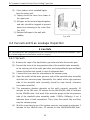
Outline of the Unit and Main Parts··················································2
3
Preparative for Installation····························································3
3.1
Standard Accessory Parts································································ 3
3.2
Selection of the Installation Location··················································· 4
3.3
Connection Pipe Requirement··························································· 5
3.4
Electrical Requirement····································································· 6
4
Installation of the Unit··································································7
4.1
Installation of the Indoor Unit····························································· 7
4.2
Installation of the Outdoor Unit ·························································11
4.3
Installation of the Connection Pipe ····················································12
4.4
Vacuum and Gas Leakage Inspection················································16
4.5
Installation of the Drain Pipe ····························································18
4.6
Electrical Wiring ············································································20
5
Installation of Controllers···························································· 25
6
Test Running··········································································· 25
6.1
Trial Operation and Testing ·····························································25
6. 2 Working Temperature Range ··························································
27
7
Troubleshooting and Maintenance ··············································· 27
7.1
Troubleshooting ············································································27
7.2
Routine Maintenance ·····································································29

DC Inverter U-match Series Floor Ceiling Type Unit
1
1
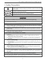
Safety Precautions
This is the safety alert symbol. It is used to alert you to potential personal injury
hazards. Obey all safety messages that follow this symbol to avoid possible
injury or death.
This mark indicates procedures which, if improperly performed, might lead to
the death or serious injury of the user.
This mark indicates procedures which, if improperly performed, might possibly
result in personal harm to the user, or damage to property.
NOTICE is used to address practices not related to personal injury.
(1). Instructions for installation and use of this product are provided by the manufacturer.
(2). Installation must be performed in accordance with the requirements of NEC and CEC by
authorized personnel only.
(3). For operating the air conditioner safely, install it as outlined in this installation manual.
(4). Connect the indoor unit and outdoor unit with the room air conditioner piping and cord available
from our standard parts. This installation manual describes the correct connections using the
installation set available from our standard parts.
(5). Installation work must be performed in accordance with national wiring standards by authorized
personnel only.
(6). If refrigerant leaks while work is being carried out, ventilate the area. If the refrigerant comes in
contact with a flame, it produces toxic gas.
(7). Do not power on until all installation work is complete.
(8). During installation, make sure that the refrigerant pipe is attached firmly before you run the
compressor.
z Do not operate the compressor under the condition of refrigerant piping not attached
properly with 2-way or 3-way valve open.
z This may cause abnormal pressure in the refrigeration cycle that leads to breakage and
even injury.
(9). During the pump-down operation, make sure that the compressor is turned off before you
remove the refrigerant piping.
z Do not remove the connection pipe while the compressor is in operation with 2-way or 3-
way valve open.
z This may cause abnormal pressure in the refrigerant cycle that leads to breakage and even
injury.
(10). When installing and relocating the air conditioner does not mix gases other than the specified
refrigerant (R410A) to enter the refrigerant cycle.
z If air or other gas enters the refrigerant cycle, the pressure inside the cycle will rise to an
abnormally high value and cause breakage, injury,etc.
(11). This appliance is not intended for use by persons (including children) with reduced physical,
sensory or mental capabilities, or lack of experience and knowledge, unless they have been
given supervision or instruction concerning use of the appliance by a person responsible for
their safety.
(12). Children should be supervised to ensure that they do not play with the appliance.
(13). If the supply cord is damaged, it must be replaced by the manufacturer, its service agent or
similarly qualified persons in order to avoid a hazard.

DC Inverter U-match Series Floor Ceiling Type Unit
2
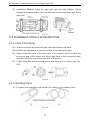
2
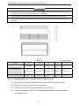
Outline of the Unit and Main Parts
Fig. 2.1
The connection pipe, drain pipe, power cord, and duct for this unit should be prepared by the
user.

DC Inverter U-match Series Floor Ceiling Type Unit
3
3
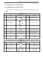
Preparative for Installation
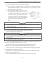
3.1 Standard Accessory Parts
The standard accessory parts listed below are furnished and should be used as
required.
Table 3.1
Indoor Unit Accessories
No. Name Appearance Q'ty Usage
1 Nut with Washer 8
To fix the hook on the
cabinet of the unit
2
Wireless Controller +
Battery
1+2 To control the indoor unit
3 Insulation 1 To insulate the gas pipe
4 Insulation 1 To insulate the liquid pipe
5 Fastener 4 To fasten the sponge
6 Nut 1 To connect gas pipe
7 Nut 1 To connect liquid pipe
Table 3.2
Outdoor Unit Accessories
No. Name Appearance Q'ty Usage
1 Drain Plug 1 or 3
To plug the unused drain
hole
2 Drainage Connecter
or
1
To connect with the hard
PVC drain pipe

DC Inverter U-match Series Floor Ceiling Type Unit
4
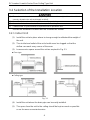
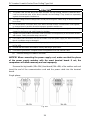
3.2 Selection of the Installation Location
ᬅ. The unit must be installed where strong enough to withstand the weight of the unit and fixed
securely, otherwise the unit would topple or fall off.
ᬆ. Do not install where there is a danger of combustible gas leakage.
ᬇ. Do not install the unit near heat source, steam, or flammable gas.
ᬈ. Children under 10 years old must be supervised not to operate the unit.
Decide the installation location with the customer as follows:
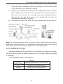
3.2.1
Indoor Unit
(1).
Install the unit at a place where is strong enough to withstand the weight of
the unit.
(2).
The air inlet and outlet of the unit should never be clogged so that the
airflow can reach every corner of theroom.
(3).
Leave service space around the unit as required in Fig.3.1.
ƹ Floor type
ƹ Ceiling type
Fig. 3.1
(4).
Install the unit where the drain pipe can be easilyinstalled.
(5).
The space from the unit to the ceiling should be kept as much as possible
so as for more convenient service.

DC Inverter U-match Series Floor Ceiling Type Unit
5
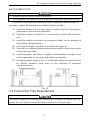
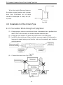
3.2.2
Outdoor Unit
ᬅ. Install the unit where it will not be tilted by more than 5°.
ᬆ. During installation, ifthe outdoor unit has to be exposed to strong wind, it must be fixed securely.
If possible, do not install the unit where it will be exposed to direct sunlight. (If
necessary, install a blind that does not interfere with the air flow.)
(1).
Install the outdoor unit in a place where it will be free from being dirty or
getting wet by rain as much aspossible.
(2).
Install the outdoor unit where it is convenient to connect with the indoor
unit.
(3).
Install the outdoor unit where the condensate water can be drained out
freely during heating operation.
(4).
Do not place animals and plants in the path of the warmair.
(5).
Take the air conditioner weight into account and select a place where noise
and vibration are small.
(6).
Install the outdoor unit where is capable of withstanding the weight of the
unit and generates as less noise and vibration aspossible.
(7).
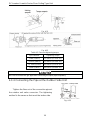
Provide the space shown in Fig. 3.2, so that the air flow is not blocked. Also
for efficient operation, leave three of four directions of peripheral
constructions open.
Fig. 3.2
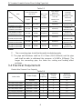
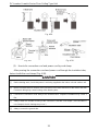
3.3 Connection Pipe Requirement
The maximum length of the connection pipe is listed in the Table below. Do not place the units
between which the distance exceeds the maximum length of the connection pipe.

DC Inverter U-match Series Floor Ceiling Type Unit
6
Table 3.3
Item
Model
Size of Fitting Pipe
mm (inch)
Max. Pipe
Length
m(feet)
Max. Height
Difference
between Indoor
Unit and
Outdoor Unit
m (feet)
Drainage
pipe(Outer
Diameter × wall
thickness)
mm (inch)
Liquid Gas
GFU18(5.3)USV4DH
GXH18(5.3)USV4DH
6(1/4) 12.7(1/2) 20(65-3/5) 15(49-1/5)
ĭ;
ĭ;
GFU24(7.0)USV4DH
GXH24(7.0)USV4DH
9.5(3/8) 16(5/8) 30(98-2/5) 15(49-1/5)
ĭ;
ĭ;
GFU30(8.8)USV4DH
GXH30(8.8)USV4DH
9.5(3/8) 16(5/8) 30(98-2/5) 15(49-1/5)
ĭ;
ĭ;
GFU36(10.6)USV4DH
GXH36(10.6)USV4DH
9.5(3/8) 16(5/8) 30(98-2/5) 15(49-1/5)
ĭ;
ĭ;
GFU42(12.3)USV4DH
GXH42(12.3)USV4DH
9.5(3/8) 16(5/8) 50(164) 30(98-2/5)
ĭ;
ĭ;
GFU48(14.1)USV4DH
GXH48(14.1)USV4DH
9.5(3/8) 16(5/8) 50(164) 30(98-2/5)
ĭ;
ĭ;
Notes:
ķ. The connecting pipe should be thermally insulatedproperly.
ĸ. The pipe wall thickness shall be 0.5~1.0mm (1/50~1/25inch) and the pipe
wall shall be able to withstand the pressure of 6.0MPa (870psig). The
longer the connecting pipe, the lower the cooling and heating effect
performs.
3.4 Electrical Requirement
Electric Wire Size and Fuse Capacity.
Table 3.4
Indoor Units
Power Supply
Fuse
Capacity
Minimum
Circuit
Ampacity
Maximum
Overcurrent
Protection
V/Ph/Hz A A A
GFU18(5.3)USV4DH 208/230V ~ 60Hz 5 1 15
GFU24(7.0)USV4DH 208/230V ~ 60Hz 5 1 15
GFU30(8.8)USV4DH 208/230V ~ 60Hz 5 2 15
GFU36(10.6)USV4DH 208/230V ~ 60Hz 5 2 15
GFU42(12.3)USV4DH 208/230V ~ 60Hz 5 2 15
GFU48(14.1)USV4DH 208/230V ~ 60Hz 5 3 15

DC Inverter U-match Series Floor Ceiling Type Unit
7
Table 3.5
Outdoor Units
Power Supply
Fuse
Capacity
Minimum Circuit
Ampacity
Maximum
Overcurrent
Protection
V/Ph/Hz A A A
GXH18(5.3)USV4DH 208/230V ~ 60Hz 5 17 25
GXH24(7.0)USV4DH 208/230V ~ 60Hz 5 24 40
GXH30(8.8)USV4DH 208/230V ~ 60Hz 5 24 40
GXH36(10.6)USV4DH 208/230V ~ 60Hz 5 29 45
GXH42(12.3)USV4DH 208/230V ~ 60Hz 5 31 50
GXH48(14.1)USV4DH 208/230V ~ 60Hz 5 45 70
Notes:
ķ. The fuse is located on the main board.
ĸ. Install the disconnect device with a contact gap of at least 3mm (1/8inch) in
all poles nearby the units (Both indoor unit and outdoor unit). The
appliance must be positioned so that the plug is accessible.
Ĺ. Take 2 pieces of power cord of 0.75mm
2
(AWG18) as the communication
lines between indoor and outdoor unit, with their longest lengths of 50m
(164feet). Please select the appropriate line length as per the actual
installation conditions. The communication lines cannot be twisted together.
For tKHXQLWNLW¶VUHFRPPHQGHGWRXVHP-1/4feet) long
communication line.
ĺ. Take 2 pieces of power cord of 0.75mm
2
(AWG18) as the communication
lines between the wired controller and the indoor unit, with their longest
lengths of 30m (98-2/5feet). Please select the appropriate line length as per
the actual installation conditions. The communication lines cannot be
twisted together. It’s recommended to use 8m (26-1/4feet) long
communication line.
Ļ. The wire size of the communication line should be no less than 0.75mm
2
(AWG18). It’s recommended to take 0.75mm
2
(AWG18) power cords as the
communication line.
4
Installation of the Unit
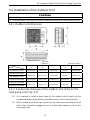
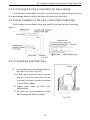
4.1 Installation of the Indoor Unit
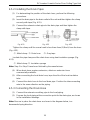
4.1.1
Indoor unit dimension

DC Inverter U-match Series Floor Ceiling Type Unit
8
ᬅ. Install the indoor unit in a location which can withstand a load of at least five times the weight of
the main unit and which will not amplify sound orvibration.
ᬆ. If the installation location is not strong enough, the indoor unit may fall and cause injuries.
ᬇ. If the job is done with the panel frame only, there is a risk that the unit will come loose. Please
take care.
Fig. 4.1
Table 4.1 Unit: mm (inch)
Model A B C D H
GFU18(5.3)USV4DH
GFU24(7.0)USV4DH
1220(48) 225(8-7/8) 1158(45-5/8) 280(11) 700(27-1/2)
GFU30(8.8)USV4DH
GFU36(10.6)USV4DH
GFU42(12.3)USV4DH
1420(55-7/8) 245(9-5/8) 1354(53-1/4) 280(11) 700(27-1/2)
GFU48(14.1)USV4DH 1700(66-7/8) 245(9-5/8) 1634(64-3/8) 280(11) 700(27-1/2)
4.1.2
Preparation for Installing the Indoor Unit
(1). Open the air inlet grille and the screw cover, and remove the screws.
(2). Release the claws in the 3 places indicated.
(3).
Release the center hook and remove the front panel.
(4).
Release the claws in the 2 or 3 places indicated and remove the electric
component cover.

DC Inverter U-match Series Floor Ceiling Type Unit
9
4.1.3
Indoor Unit Installation
(1).
Determine the location of the hanger through the paper template, and then
remove the paper template.
Fig. 4.2
(2).
Insert the anchor bolts into the drilled holes, and drive the pins completely
into the anchor bolts with a hammer.
(3).
Remove the right and left side panels.
(4).
Put the hanger bolt into the clasp of the indoor unit and tighten screws on
the hanger to prevent the indoor unit from moving.
(5).
Reinstall and tighten the right and left sidepanels.
ƹ Floor type
Fig. 4.3

DC Inverter U-match Series Floor Ceiling Type Unit
10
ƹ Ceiling type
Fig. 4.4
(6).
Adjust the height of the unit to make the drain pipe slant slightly downward
so that the drainage will become much smoother.
4.1.4
Leveling
The water level test must be done after installing the indoor unit to make the unit
is horizontal, as shown below.
Fig. 4.5
y

DC Inverter U-match Series Floor Ceiling Type Unit
11
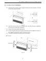
4.2 Installation of the Outdoor Unit
ᬅ. Install the unit where it will not be tilted by more than 5°.
ᬆ. During installation, if the outdoor unit has to be exposed to strong wind, it must be fixed securely.
4.2.1
Outdoor unit dimension
Fig. 4.6
Table 4.2 Unit: mm (inch)
Item
Model
ABCDE
GXH18(5.3)USV4DH 955(37-5/8) 396(15-5/8) 700(27-1/2) 560(22) 360(14-1/8)
GXH24(7.0)USV4DH
980(38-5/8) 427(16-3/4) 790(31-1/8) 610(24) 395(15-1/2)
GXH30(8.8)USV4DH
GXH36(10.6)USV4DH 1107(43-5/8) 440(17-3/8) 1100(43-1/4) 631(24-7/8) 400(15-3/4)
GXH42(12.3)USV4DH
958(37-3/4) 412(16-1/4) 1349(53-1/8) 572(22-1/2) 376(14-3/4)
GXH48(14.1)USV4DH
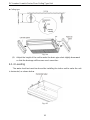
4.2.2
Condensate Drainage of the Outdoor Unit (Only for the
heat pump unit) (Fig. 4.7)
(1).
It is required to install a drain pipe for the outdoor unit to drain out the
condensate water during heating operation (only for the heat pumpunit).
(2).
When installing the drain pipe, apart from the drain pipe mounting hole, all
other holes should be plugged so as to avoid water leakage (only for the
heat pump unit).

DC Inverter U-match Series Floor Ceiling Type Unit
12
(3).
,QVWDOODWLRQ 0HWKRG ,QVHUW WKH SLSH MRLQW LQWR WKH KROH ijPP LQFK
located at the base plate of the unit and then connect the drain pipe to the
pipe joint.
Fig. 4.7
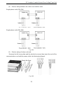
4.3 Installation of the Connection Pipe
4.3.1
Flare Processing
(1). Cut the connection pipe with the pipe cutter and remove the burrs.
(2). Hold the pipe downward to prevent cuttings from entering the pipe.
(3).
Remove the flare nuts at the stop valve of the outdoor unit and inside the
accessory bag of the indoor unit, then insert them to the connection pipe,
after that, flare the connection pipe with a flaringtool.
(4).
Check if the flare part is spread evenly and there are no cracks (see Fig.
4.8).
4.3.2
Bending Pipes
Fig. 4.8
(1). The pipes are shaped by your hands. Be careful not to collapse them.
Fig. 4.9

13
DC Inverter U-match Series Floor Ceiling Type Unit
(2).
Do not bend the pipes in an angle more than90°.
(3).
When pipes are repeatedly bent or stretched, the material will harden,
making it difficult to bend or stretch them anymore. Do not bend or stretch
the pipes more than three times.
(4). When bending the pipe, do not bend it as is.
The pipe will be collapsed. In this case, cut
the heat insulating pipe with a sharp cutter
as shown in Fig. 4.10, and bend it after
exposing the pipe. After bending the pipe as
you want, be sure to put the heat insulating
pipe back on the pipe, and secure it with
tape.
Fig. 4.10
ᬅ. To prevent breaking of the pipe, avoid sharp bends. Bend the pipe with a radius of curvature of
150mm (5-7/8inch) or over.
ᬆ. If the pipe is bent repeatedly at the same place, it will break.
4.3.3
Connecting the Pipe at the Indoor Unit Side
Detach the caps and plugs from the pipes.
ᬅ. Be sure to apply the pipe against the port on the indoor unit correctly. If the centering is
improper, the flare nut cannot be tightened smoothly. If the flare nut is forced to turn, the threads
will be damaged.
ᬆ. Do not remove the flare nut until the connection pipe is to be connected so as to prevent dust
and impurities from coming into the pipesystem.
When connecting the pipe to the unit or removing it from the unit, please do use
both the spanner and the torque wrench (Fig. 4.11).
When connecting, smear both inside and outside of the flare nut with
refrigeration oil, screw it hand tight and then tighten it with the spanner.
Refer to Table 4.3 to check if the wrench has been tightened properly (too tight
would mangle the nut and lead to leakage).
Examine the connection pipe to see if it leaks, then take the treatment of heat
insulation, as shown in the Fig. 4.12.
Use the medium-sized sponge to insulate the coupler of the gas pipe.

14
DC Inverter U-match Series Floor Ceiling Type Unit
Fig. 4.11
Fig. 4.12
Table 4.3 Flare nut tightening torque
Pipe Diameter Tightening Torque
6mm (1/4inch) 15~30N·m (11~22ft.-1b.)
9.5mm (3/8inch) 35~40N·m (26~29ft.-1b.)
12.7mm (1/2inch) 45~50N·m (33~37ft.-1b.)
16mm (5/8inch) 60~65N·m (44~48ft.-1b.)
Be sure to connect the gas pipe after connecting the liquid pipe completely.
4.3.4
Connecting the Pipe at the Outdoor Side Unit
Tighten the flare nut of the connection pipe at
the outdoor unit valve connector. The tightening
method is the same as that as at the indoor side.
Fig. 4.13
g

15
DC Inverter U-match Series Floor Ceiling Type Unit
4.3.5
Checking the Pipe Connections for Gas Leaking
For both indoor and outdoor unit side, check the joints for gas leaking by the use
of a gas leakage detector without fail when the pipes are connected.
4.3.6
Heat Insulation on the Pipe Joints (Indoor Side Only)
Stick coupler heat insulation (large and small) to the place where connecting
pipes.
Fig. 4.14
4.3.7
Liquid Pipe and Drain Pipe
(1).
If the outdoor unit is installed lower than
the indoor unit (See Fig.4.15)
1).
A drain pipe should be above ground
and the end of the pipe does not dip
into water. All pipes must be restrained
to the wall by saddles.
2).
Taping pipes must be done from
bottom to top.
3).
All pipes are bound together by tape
and restrained to wall by saddles.
Fig. 4.15

16
DC Inverter U-match Series Floor Ceiling Type Unit
(2).
If the outdoor unit is installed higher
than the indoor unit
1).
Taping should be done from lower to
the upper part.
2).
All pipes are bound and taped together
and also should be trapped to prevent
water from returning to the room (See
Fig. 4.16).
3).
Restraint all pipes to the wall with
saddles.
Fig. 4.16
4.4 Vacuum and Gas Leakage Inspection
Do not purge the air with refrigerants but use a vacuum pump to vacuum the installation There
is no extra refrigerant in the outdoor unit for air purging
4.4.1
Vacuum
(1). Remove the caps of the liquid valve, gas valve and also the service port.
(2). Connect the hose at the low pressure side of the manifold valve assembly
to the service port of the unit’s gas valve, and meanwhile the gas and liquid
valves should be kept closed in case of refrigerant leak.
(3).
Connect the hose used for evacuation to the vacuum pump.
(4).
Open the switch at the lower pressure side of the manifold valve assembly
and start the vacuum pump. Meanwhile, the switch at the high pressure
side of the manifold valve assembly should be kept closed, otherwise
evacuation would fail.
(5).
The evacuation duration depends on the unit’s capacity, generally, 20
minutes for the 18k units, 30 minutes for the 24k/30k/36k units, 45 minutes
for the 42k/48k units. And verify if the pressure gauge at the low pressure
side of the manifold valve assembly reads -1.0MPa (145psig), if not, it
indicates there is leak somewhere. Then, close the switch fully and then
stop the vacuum pump.
(6).
Wait for some time to see if the system pressure can remain unchanged, 3
minutes for the 18k/24k units, 10 minutes for the 30k/36k/42k/48k units.

17
DC Inverter U-match Series Floor Ceiling Type Unit
During this time, the reading of the pressure gauge at the low pressure side
cannot be larger than 0.005MPa (0.72psig).
(7).
Slightly open the liquid valve and let some refrigerant go to the connection
pipe to balance the pressure inside and outside of the connection pipe, so
that air will not come into the connection pipe when removing the hose.
Note that the gas and liquid valve can be opened fully only after the
manifold valve assembly is removed.
(8).
Place back the caps of the liquid valve, gas valve and also the serviceport.
Fig. 4.17
Note: For the large-sized unit, it has the service port for both the gas valve and the
liquid valve. During evacuation, it is available to connect two hoses of the manifold
valve assembly to two service ports to quicken the evacuating speed.
4.4.2
Additional Charge
Refrigerant suitable for a piping length of 7.6m (25feet) is charged in the outdoor
unit at the factory. When the piping is longer than 7.6m (25feet), additional charging
is necessary.
For the additional amount, see Table 4.4.
Table 4.4
Item
Model
Additional Refrigerant Amount for Extra Pipe
18k 45g per 1.5m (1.6 ounce per 5 feet)
24k~48k 90g per 1.5m (3.2 ounce per 5 feet)

18
DC Inverter U-match Series Floor Ceiling Type Unit
When the height difference between
the indoor unit and outdoor unit is larger
than 10m (32-4/5feet), an oil bend
should be employed for every 6m (19-
2/3 feet).
Fig. 4.18
4.5 Installation of the Drain Pipe
4.5.1
Precautions When Doing the PipingWork
(1).
Keep piping as short as possible and slope it downwards at a gradientof at
least 1/100 so that air may not remain trapped inside the pipe.
(2).
Keep pipe size equal to or greater than that of the connecting pipe.
(3).
Install the drain piping as shown and take measures against condensation.
Improperly rigged piping could lead to leaks and eventually wet furniture
and belongings.
Fig. 4.19
(4).
Connect the drain hose (Fig. 4.20).
Fig. 4.20
Page is loading ...
Page is loading ...
Page is loading ...
Page is loading ...
Page is loading ...
Page is loading ...
Page is loading ...
Page is loading ...
Page is loading ...
Page is loading ...
Page is loading ...
Page is loading ...
-
 1
1
-
 2
2
-
 3
3
-
 4
4
-
 5
5
-
 6
6
-
 7
7
-
 8
8
-
 9
9
-
 10
10
-
 11
11
-
 12
12
-
 13
13
-
 14
14
-
 15
15
-
 16
16
-
 17
17
-
 18
18
-
 19
19
-
 20
20
-
 21
21
-
 22
22
-
 23
23
-
 24
24
-
 25
25
-
 26
26
-
 27
27
-
 28
28
-
 29
29
-
 30
30
-
 31
31
-
 32
32


Unbranded U-Match Installation guide
- Type
- Installation guide
- This manual is also suitable for
Ask a question and I''ll find the answer in the document
Finding information in a document is now easier with AI
Related papers
-
Gibson U-Match Installation guide
-
-
-
-
-
-
-
Other documents
-
Dettson OLC_DLC Installation guide
-
Western WAC-R32 Owner's manual
-
-
Nortek GXH09(2.6)LSA4DL2 Mini Split Heat Pump Systems Owner's manual
-
-
 Kaisai Duct Installation guide
-
 Western Airconditioning DBIS-24 User manual
-
Carrier 40WAH Installation guide
-
Johnson Controls DCPM09NWM41Q1 User manual
-
Tosot TM09HTDI Multi Zone Floor Ceiling Console Manual

