Page is loading ...

DUCT TYPE
INSTALLATION MANUAL
Ceiling And Floor Type
Thank you very much for purchasing our air conditioner,
Before using your air conditioner, please read this manual carefully and keep it for
future reference.
INSTALLATION MANUAL


DC Inverter U-match Series Duct Type Unit
1
1 Safety Precautions
WARNING! This mark indicates procedures which, if improperly performed, might lead to the
death or serious injury of the user.
CAUTION! This mark indicates procedures which, if improperly performed, might possibly
result in personal harm to the user, or damage to property.
WARNING!
(1). For operating the air conditioner pleasantly, install it as outlined in this installation manual.
(2). Connect the indoor unit and outdoor unit with the room air conditioner piping and cord available
from our standard parts. This installation manual describes the correct connections using the
installation set available from our standard parts.
(3). Installation work must be performed in accordance with national wiring standards by authorized
personnel only.
(4). If refrigerant leaks while work is being carried out, ventilate the area. If the refrigerant comes in
contact with a ame, it produces toxic gas.
(5). Do not power on until all installation work is complete.
(6). During installation, make sure that the refrigerant pipe is attached firmly before you run the
compressor.
Do not operate the compressor under the condition of refrigerant piping not attached properly with
2-way or 3-way valve open.
This may cause abnormal pressure in the refrigeration cycle that leads to breakage and even
injury.
(7). During the pump-down operation, make sure that the compressor is turned off before you remove
the refrigerant piping.
Do not remove the connection pipe while the compressor is in operation with 2-way or 3-way
valve open.
This may cause abnormal pressure in the refrigerant cycle that leads to breakage and even injury.
(8). When installing and relocating the air conditioner, do not mix gases other than the specified
refrigerant (R410A) to enter the refrigerant cycle.
If air or other gas enters the refrigerant cycle, the pressure inside the cycle will rise to an
abnormally high value and cause breakage, injury, etc.
(9). This appliance is not intended for use by persons (including children) with reduced physical,
sensory or mental capabilities, or lack of experience and knowledge, unless they have been
given supervision or instruction concerning use of the appliance by a person responsible for their
safety.
(10). Children should be supervised to ensure that they do not play with the appliance.
(11). If the supply cord is damaged, it must be replaced by the manufacturer, its service agent or
similarly qualied persons in order to avoid a hazard.
3
kaisai.com

DC Inverter U-match Series Duct Type Unit
2
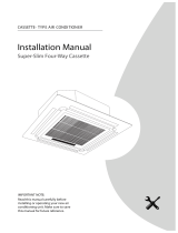
2 Outline of the Unit and Main Parts
Indoor
Outdoor
1. power Cord
2. Electric Box
3. Wired controller
4. Wireless Controller
5. Binding tape
6. Drain Pipe
7. Gas Pipe
8. Lipuid Pipe
9. Big Handle
10. Front Board
1 2
3 4
5
679 810
Air outlet
Air outlet
Air inlet
Air inlet
Fig.1
NOTE!
① .
The connection pipe and duct for this unit should be prepared by the user.
② .
The unit is standard equipped with rectangular duct.
4kaisai.com

DC Inverter U-match Series Duct Type Unit
2
2 Outline of the Unit and Main Parts
Indoor
Outdoor
1. power Cord
2. Electric Box
3. Wired controller
4. Wireless Controller
5. Binding tape
6. Drain Pipe
7. Gas Pipe
8. Lipuid Pipe
9. Big Handle
10. Front Board
1 2
3 4
5
679 810
Air outlet
Air outlet
Air inlet
Air inlet
Fig.1
NOTE!
① .
The connection pipe and duct for this unit should be prepared by the user.
② .
The unit is standard equipped with rectangular duct.
DC Inverter U-match Series Duct Type Unit
3
3 Preparative for Installation
3.1 Standard Accessory Parts
The standard accessory parts listed below are furnished and should be used as required.
Table 1
Indoor Unit Accessories
No. Name Appearance Q'ty Usage
1 Wired Controller 1 To control the indoor unit
2 Hanger or 4 To x the indoor unit
3 Nut with Washer 8To x the hook on the cabinet
of the unit.
4 Nut with Washer 4To x the hook on the cabinet
of the unit.
5 Nut 4
To be used together with the
hanger bolt for installing the
unit.
6 Washer 4
To be used together with the
hanger bolt for installing the
unit.
7 Insulation 1 To insulate the gas pipe
8 Insulation 1 To insulate the liquid pipe
9 Fastener 8 To fasten the sponge
10 Nut 1 To connect liquid pipe
11 Nut 1 To connect gas pipe
5
kaisai.com

DC Inverter U-match Series Duct Type Unit
4
Table 2
Outdoor Unit Accessories
No. Name Appearance Q'ty Usage
1 Drain Plug 3 To plug the unused drain hole.
2 Drainage Connecter or 1To connect with the hard PVC
drain pipe
3.2 Selection of the Installation Location
WARNING!
The unit must be installed where strong enough to withstand the weight of the unit and xed securely,
otherwise the unit would topple or fall off.
CAUTION!
① .
Do not install where there is a danger of combustible gas leakage.
② .
Do not install the unit near heat source, steam, or ammable gas.
③ .
Children under 10 years old must be supervised not to operate the unit.
Decide the installation location with the customer as follows:
3.2.1 Indoor Unit
(1). Install the unit at a place where is strong enough to withstand the weight of the unit.
(2). The air inlet and outlet of the unit should never be clogged so that the airow can reach
every corner of the room.
(3). Leave service space around the unit as required in Fig.2.
Fig.2
(4). Install the unit where the drain pipe can be easily installed.
(5). The space from the unit to the ceiling should be kept as much as possible so as for more
convenient service.
6kaisai.com

DC Inverter U-match Series Duct Type Unit
4
Table 2
Outdoor Unit Accessories
No. Name Appearance Q'ty Usage
1 Drain Plug 3 To plug the unused drain hole.
2 Drainage Connecter or 1To connect with the hard PVC
drain pipe
3.2 Selection of the Installation Location
WARNING!
The unit must be installed where strong enough to withstand the weight of the unit and xed securely,
otherwise the unit would topple or fall off.
CAUTION!
① .
Do not install where there is a danger of combustible gas leakage.
② .
Do not install the unit near heat source, steam, or ammable gas.
③ .
Children under 10 years old must be supervised not to operate the unit.
Decide the installation location with the customer as follows:
3.2.1 Indoor Unit
(1). Install the unit at a place where is strong enough to withstand the weight of the unit.
(2). The air inlet and outlet of the unit should never be clogged so that the airow can reach
every corner of the room.
(3). Leave service space around the unit as required in Fig.2.
Fig.2
(4). Install the unit where the drain pipe can be easily installed.
(5). The space from the unit to the ceiling should be kept as much as possible so as for more
convenient service.
DC Inverter U-match Series Duct Type Unit
5
3.2.2 Outdoor Unit
WARNING!
① .
Install the unit where it will not be tilted by more than 5°.
② .
During installation, if the outdoor unit has to be exposed to strong wind, it must be fixed
securely.
(1). If possible, do not install the unit where it will be exposed to direct sunlight. (If necessary,
install a blind that does not interfere with the air ow.)
(2). Install the outdoor unit in a place where it will be free from getting dirty or getting wet by
rain as much as possible.
(3). Install the outdoor unit where it is convenient to connect the indoor unit.
(4). Install the outdoor unit where the condensate water can be drained out freely during
heating operation. Do not place animals and plants in the path of the warm air.
(5). Take the air conditioner weight into account and select a place where noise and vibration
are small.
(6). Install the outdoor unit where is capable of withstanding the weight of the unit and
generates as less noise and vibration as possible.
(7). Provide the space shown in Fig.3, so that the air flow is not blocked. Also for efficient
operation, leave three of four directions of peripheral constructions open.
Units: mm
>500
>500 >500 >500
>2000
>2000
>1000
Fig.3
3.3 Connection Pipe Requirement
CAUTION!
The maximum length of the connection pipe is listed in the table below. Do not place the units between
which the distance exceeds the maximum length of the connection pipe.
7
kaisai.com

DC Inverter U-match Series Duct Type Unit
6
Table 3
Size of Fitting
Pipe(Inch)
Max.
Pipe
Length
(m)
Max. Height
Difference between
Indoor Unit and
Outdoor Unit (m)
Drainage
pipe(Outer
Diameter × wall
thickness) (mm)
Liquid Gas
GFH09K3FI GUHD09NK3FO 1/4 3/8 20 15 Φ20X1.2
GFH12K3FI GUHD12NK3FO 1/4 3/8 20 15 Φ30X1.5
GFH18K3FI GUHD18NK3FO 1/4 1/2 20 15 Φ30X1.5
GFH24K3FI GUHD24NK3FO 3/8 5/8 30 15 Φ20X1.2
GFH30K3FI GUHD30NK3FO 3/8 5/8 30 15 Φ20X1.2
GFH36K3FI GUHD36NK3FO 3/8 5/8 30 15 Φ20X1.2
GFH42K3FI GUHD42NK3FO 3/8 5/8 50 30 Φ20X1.2
GFH48K3FI GUHD48NK3FO 3/8 5/8 50 30 Φ20X1.2
GFH36K3FI GUHD36NM3FO 3/8 5/8 30 15 Φ20X1.2
GFH42K3FI GUHD42NM3FO 3/8 5/8 50 30 Φ20X1.2
GFH48K3FI GUHD48NM3FO 3/8 5/8 50 30 Φ20X1.2
GFH60K3FI GUHD60NM3FO 3/8 3/4 50 30 Φ20X1.2
① .
The connection pipe should be insulated with proper water-proof insulating material.
② .
The pipe wall thickness shall be 0.5-1.0mm and the pipe wall shall be able to withstand the
pressure of 6.0 MPa.The longer the connecting pipe, the lower the cooling and heating effect
performs.
3.4 Electrical Requirement
Electric Wire Size and Fuse Capacity.
Table 4
Indoor Units Power Supply Fuse Capacity Breaker Capacity Min. Power Supply
Cord
V/Ph/Hz A A mm2
09K~60K 220-240V~ 50Hz 5 6 1.0
Table 5
Model Power
Supply
Capability of Air
Switch(A)
Minimum Sectional Area of Power Cable
and Earth line (mm2)
GUHD09NK3FO
220-240V
~50Hz
13 1.5
GUHD12NK3FO 13 1.5
GUHD18NK3FO 16 1.5
GUHD24NK3FO 20 2.5
GUHD30NK3FO 20 2.5
GUHD36NK3FO 25 2.5
GUHD42NK3FO 25 2.5
GUHD48NK3FO 40 6.0
GUHD36NM3FO
380-415V 3N ~
50Hz
10 1.5
GUHD42NM3FO 10 1.5
GUHD48NM3FO 16 1.5
GUHD60NM3FO 16 1.5
Item
Model
8kaisai.com

DC Inverter U-match Series Duct Type Unit
6
Table 3
Size of Fitting
Pipe(Inch)
Max.
Pipe
Length
(m)
Max. Height
Difference between
Indoor Unit and
Outdoor Unit (m)
Drainage
pipe(Outer
Diameter × wall
thickness) (mm)
Liquid Gas
GFH09K3FI GUHD09NK3FO 1/4 3/8 20 15 Φ20X1.2
GFH12K3FI GUHD12NK3FO 1/4 3/8 20 15 Φ30X1.5
GFH18K3FI GUHD18NK3FO 1/4 1/2 20 15 Φ30X1.5
GFH24K3FI GUHD24NK3FO 3/8 5/8 30 15 Φ20X1.2
GFH30K3FI GUHD30NK3FO 3/8 5/8 30 15 Φ20X1.2
GFH36K3FI GUHD36NK3FO 3/8 5/8 30 15 Φ20X1.2
GFH42K3FI GUHD42NK3FO 3/8 5/8 50 30 Φ20X1.2
GFH48K3FI GUHD48NK3FO 3/8 5/8 50 30 Φ20X1.2
GFH36K3FI GUHD36NM3FO 3/8 5/8 30 15 Φ20X1.2
GFH42K3FI GUHD42NM3FO 3/8 5/8 50 30 Φ20X1.2
GFH48K3FI GUHD48NM3FO 3/8 5/8 50 30 Φ20X1.2
GFH60K3FI GUHD60NM3FO 3/8 3/4 50 30 Φ20X1.2
① .
The connection pipe should be insulated with proper water-proof insulating material.
② .
The pipe wall thickness shall be 0.5-1.0mm and the pipe wall shall be able to withstand the
pressure of 6.0 MPa.The longer the connecting pipe, the lower the cooling and heating effect
performs.
3.4 Electrical Requirement
Electric Wire Size and Fuse Capacity.
Table 4
Indoor Units Power Supply Fuse Capacity Breaker Capacity Min. Power Supply
Cord
V/Ph/Hz A A mm2
09K~60K 220-240V~ 50Hz 5 6 1.0
Table 5
Model Power
Supply
Capability of Air
Switch(A)
Minimum Sectional Area of Power Cable
and Earth line (mm2)
GUHD09NK3FO
220-240V
~50Hz
13 1.5
GUHD12NK3FO 13 1.5
GUHD18NK3FO 16 1.5
GUHD24NK3FO 20 2.5
GUHD30NK3FO 20 2.5
GUHD36NK3FO 25 2.5
GUHD42NK3FO 25 2.5
GUHD48NK3FO 40 6.0
GUHD36NM3FO
380-415V 3N ~
50Hz
10 1.5
GUHD42NM3FO 10 1.5
GUHD48NM3FO 16 1.5
GUHD60NM3FO 16 1.5
Item
Model
DC Inverter U-match Series Duct Type Unit
7
Note:
① .
The fuse is located on the main board.
② .
Install the disconnect device with a contact gap of at least 3mm in all poles nearby the units
(Both indoor unit and outdoor unit).The appliance must be positioned so that the plug is
accessible.
③ .
The specications of the breaker and power cable listed in the table above are determined
based on the maximum power (maximum amps) of the unit.
④ .
The specifications of the power cable listed in the table above are applied to the conduit-
guarded multi-wire copper cable (like, YJV copper cable, consisting of PE insulated wires and
a PVC cable jacket) used at 40°С and resistible to 90°С(see IEC 60364-5-52). If the working
condition changes, they should be modied according to the related national standard.
⑤ .
The specifications of the breaker listed in the table above are applied to the breaker with
the working temperature at 40°С. If the working condition changes, they should be modied
according to the related national standard.
⑥ .
Take 2 pieces of power cord of 0.75mm2 as the communication lines between indoor and
outdoor unit, with their longest lengths of 50m. Please select the appropriate line length as per
the actual installation conditions. The communication lines can not be twisted together. For
the unit (≤30K), it’s recommended to use 8m long communication line.
⑦ .
Take 2 pieces of power cord of 0.75mm2 as the communication lines between the wired
controller and the indoor unit, with their longest lengths of 30m. Please select the appropriate
line length as per the actual installation conditions. The communication lines can not be twisted
together. It’s recommended to use 8m long communication line.
⑧ .
The wire size of the communication line should be no less than 0.75mm2. It’s recommended to
take 0.75mm2 power cords as the communication line.
4 Installation of the Unit
4.1 Installation of the Indoor Unit
4.1.1 Indoor unit dimension
WARNING!
① .
Install the indoor unit in a location which can withstand a load of at least ve times the weight
of the main unit and which will not amplify sound or vibration.
② .
If the installation location is not strong enough, the indoor unit may fall and cause injuries.
③ .
If the job is done with the panel frame only, there is a risk that the unit will come loose. Please
take care.
9
kaisai.com

DC Inverter U-match Series Duct Type Unit
8
For the units: 09~18K
J
B
H
I
G
F
Max
Air intake
E
D
C
Max
A
For the units: 24~42K
J
I
H
G
B
F
A
E
C
D
Gas Pipe Liquid Pipe
Drainage Pipe Electric Box
Air Intake
Max
Max
10 kaisai.com

DC Inverter U-match Series Duct Type Unit
8
For the units: 09~18K
J
B
H
I
G
F
Max
Air intake
E
D
C
Max
A
For the units: 24~42K
J
I
H
G
B
F
A
E
C
D
Gas Pipe Liquid Pipe
Drainage Pipe Electric Box
Air Intake
Max
Max
DC Inverter U-match Series Duct Type Unit
9
For the units: 48k,60k
J
H
A
B
D
E
G
I
F
C
Fig.4
Table 6
Item
Model A B C D E F G H I J
GFH09K3FI 840 561 635 790 925 665 738 125 203 250
GFH12K3FI
945 618 738 892 1037 721 738 125 203 266
GFH18K3FI
GFH24K3FI
1101 517 820 1159 1279 558 1002 160 235 268
GFH30K3FI
GFH36K3FI
1011 748 820 1115 1226 775 979 160 231 290
GFH42K3FI
GFH48K3FI 1177 646 852 1150 1340 750 953 190 316 350
GFH60K3FI
11
kaisai.com

DC Inverter U-match Series Duct Type Unit
10
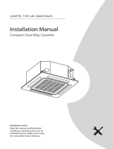
4.1.2 Drilling Holes for Bolts and Installing the Bolts
Using the installation template, drill holes for bolts (four holes). (Fig. 5)
4.1.3 Installing the Suspension Bolts
(1). Install the bolts to the ceiling at a place strong enough to hang the unit. Mark the bolt
positions from the installation template. With a concrete drill, drill for 12.7mm (1/2”)
diameter holes. (Fig. 6)
(2). Insert the anchor bolts into the drilled holes, and drive the pins completely into the anchor
bolts with a hammer. (Fig. 7)
(3). Install the hanger to the unit. (Fig.8)
(4). Pass the unit hangers over the bolts installed to the ceiling and install the unit with the
special nut.(Fig.9)
60 to 70 mm
Fig.6Fig. 5 Fig.7
Φ12.7mm
Fig.8
Hanger
I
I
2:1
Hook Screw
Nut
Nut
Fig.9
12 kaisai.com

DC Inverter U-match Series Duct Type Unit
10
4.1.2 Drilling Holes for Bolts and Installing the Bolts
Using the installation template, drill holes for bolts (four holes). (Fig. 5)
4.1.3 Installing the Suspension Bolts
(1). Install the bolts to the ceiling at a place strong enough to hang the unit. Mark the bolt
positions from the installation template. With a concrete drill, drill for 12.7mm (1/2”)
diameter holes. (Fig. 6)
(2). Insert the anchor bolts into the drilled holes, and drive the pins completely into the anchor
bolts with a hammer. (Fig. 7)
(3). Install the hanger to the unit. (Fig.8)
(4). Pass the unit hangers over the bolts installed to the ceiling and install the unit with the
special nut.(Fig.9)
60 to 70 mm
Fig.6Fig. 5 Fig.7
Φ12.7mm
Fig.8
Hanger
I
I
2:1
Hook Screw
Nut
Nut
Fig.9
DC Inverter U-match Series Duct Type Unit
11
4.1.4 Leveling
The water level test must be done after installing the indoor unit to make the unit is horizontal,
as shown below.
Horizontal tester
4.2 Installation of the Outdoor Unit
WARNING
① .
Install the unit where it will not be tilted by more than 5°.
② .
During installation, if the outdoor unit has to be exposed to strong wind, it must be fixed
securely.
4.2.1 Outdoor unit dimension
D
A
B
C
E
Fig.11
Table 6 Unit: mm
Item
Model ABCDE
GUHD09NK3FO
GUHD12NK3FO 848 320 540 540 286
GUHD18NK3FO 955 396 700 560 360
Fig.10
13
kaisai.com

DC Inverter U-match Series Duct Type Unit
12
GUHD24NK3FO
GUHD30NK3FO 980 427 790 610 395
GUHD36NK3FO
GUHD36NM3FO 1107 440 1100 631 400
GUHD42NM3FO
GUHD42NK3FO
GUHD48NK3FO
GUHD48NM3FO
958 412 1349 572 376
GUHD60NM3FO 1085 427 1365 620 395
4.2.2 Condensate Drainage of the Outdoor Unit(Only for the heat pump unit) (Fig.12)
(1). It is required to install a drain pipe for the outdoor unit to drain out the condensate water
during heating operation. (only for the heat pump unit)
(2). When installing the drain pipe, apart from the drain pipe mounting hole, all other holes
should be plugged so as to avoid water leakage.(only for the heat pump unit)
(3). Installation Method: Insert the pipe joint into the hole φ25 located at the base plate of the
unit and then connect the drain pipe to the pipe joint.
Bottom Drain cap
Drain pipe mounting hole
Fig.12
4.3 Installation of the Connection Pipe
4.3.1 Flare Processing
(1). Cut the connection pipe with the pipe cutter and remove the burrs.
(2). Hold the pipe downward to prevent cuttings from entering the pipe.
(3). Remove the are nuts at the stop valve of the outdoor unit and inside the accessory bag of
the indoor unit, then insert them to the connection pipe, after that, are the connection pipe
with a aring tool.
(4). Check if the are part is spread evenly and there are no cracks (see Fig.13).
Fig.13
14 kaisai.com

DC Inverter U-match Series Duct Type Unit
12
GUHD24NK3FO
GUHD30NK3FO 980 427 790 610 395
GUHD36NK3FO
GUHD36NM3FO 1107 440 1100 631 400
GUHD42NM3FO
GUHD42NK3FO
GUHD48NK3FO
GUHD48NM3FO
958 412 1349 572 376
GUHD60NM3FO 1085 427 1365 620 395
4.2.2 Condensate Drainage of the Outdoor Unit(Only for the heat pump unit) (Fig.12)
(1). It is required to install a drain pipe for the outdoor unit to drain out the condensate water
during heating operation. (only for the heat pump unit)
(2). When installing the drain pipe, apart from the drain pipe mounting hole, all other holes
should be plugged so as to avoid water leakage.(only for the heat pump unit)
(3). Installation Method: Insert the pipe joint into the hole φ25 located at the base plate of the
unit and then connect the drain pipe to the pipe joint.
Bottom Drain cap
Drain pipe mounting hole
Fig.12
4.3 Installation of the Connection Pipe
4.3.1 Flare Processing
(1). Cut the connection pipe with the pipe cutter and remove the burrs.
(2). Hold the pipe downward to prevent cuttings from entering the pipe.
(3). Remove the are nuts at the stop valve of the outdoor unit and inside the accessory bag of
the indoor unit, then insert them to the connection pipe, after that, are the connection pipe
with a aring tool.
(4). Check if the are part is spread evenly and there are no cracks (see Fig.13).
Fig.13
DC Inverter U-match Series Duct Type Unit
13
4.3.2 Bending Pipes
(1). The pipes are shaped by your hands. Be careful not to collapse them.
×
√
Fig.14
(2). Do not bend the pipes in an angle more than 90°.
(3). When pipes are repeatedly bent or stretched, the material will harden, making it difcult to
bend or stretch them any more. Do not bend or stretch the pipes more than three times.
(4). When bending the pipe, do not bend it as is. The pipe will
be collapsed. In this case, cut the heat insulating pipe
with a sharp cutter as shown in Fig.15, and bend it after
exposing the pipe. After bending the pipe as you want, be
sure to put the heat insulating pipe back on the pipe, and
secure it with tape. Fig.15
Pipe
Cutter
Cutt line
Heat insulating
pipe
CAUTION!
① .
To prevent breaking of the pipe, avoid sharp bends. Bend the pipe with a radius of curvature
of 150 mm or over.
② .
If the pipe is bent repeatedly at the same place, it will break.
4.3.3 Connecting the Pipe at the Indoor Unit Side
Detach the caps and plugs from the pipes.
CAUTION!
① .
Be sure to apply the pipe against the port on the indoor unit correctly. If the centering is
improper, the flare nut cannot be tightened smoothly. If the flare nut is forced to turn, the
threads will be damaged.
② .
Do not remove the are nut until the connection pipe is to be connected so as to prevent dust
and impurities from coming into the pipe system.
Centering the pipe against port on the indoor unit, turn the are nut with your hand.
CAUTION!
Hold the torque wrench at its grip, keeping it in the right angle with the pipe as shown in Fig. 15,
in order to tighten the are nut correctly.
15
kaisai.com

DC Inverter U-match Series Duct Type Unit
14
When the are nut is tightened properly by your hand, use a torque wrench to nally tighten it.
Fig.16
Fig.17
Table 7 Flare nut tightening torque
Pipe Diameter Tightening Torque
1/4˝(Inch) 15-30 (N·m)
3/8˝(Inch) 35-40 (N·m)
5/8˝(Inch) 60-65 (N·m)
1/2˝(Inch) 45-50 (N·m)
3/4˝(Inch) 70-75 (N·m)
7/8˝(Inch) 80-85 (N·m)
CAUTION!
Be sure to connect the gas pipe after connecting the liquid pipe completely.
4.3.4 Connecting the Pipe at the Outdoor Side Unit
Tighten the flare nut of the connection pipe at the outdoor unit
valve connector. The tightening method is the same as that as at the
indoor side.
4.3.5 Checking the Pipe Connections for Gas Leaking
For both indoor and outdoor unit side, check the joints for gas
leaking by the use of a gas leakage detector without fail when the
pipes are connected.
4.3.6 Heat Insulation on the Pipe Joints (Indoor Side Only)
Stick coupler heat insulation (large and small) to the place where connecting pipes.
Fig.18
16 kaisai.com

DC Inverter U-match Series Duct Type Unit
14
When the are nut is tightened properly by your hand, use a torque wrench to nally tighten it.
Fig.16
Fig.17
Table 7 Flare nut tightening torque
Pipe Diameter Tightening Torque
1/4˝(Inch) 15-30 (N·m)
3/8˝(Inch) 35-40 (N·m)
5/8˝(Inch) 60-65 (N·m)
1/2˝(Inch) 45-50 (N·m)
3/4˝(Inch) 70-75 (N·m)
7/8˝(Inch) 80-85 (N·m)
CAUTION!
Be sure to connect the gas pipe after connecting the liquid pipe completely.
4.3.4 Connecting the Pipe at the Outdoor Side Unit
Tighten the flare nut of the connection pipe at the outdoor unit
valve connector. The tightening method is the same as that as at the
indoor side.
4.3.5 Checking the Pipe Connections for Gas Leaking
For both indoor and outdoor unit side, check the joints for gas
leaking by the use of a gas leakage detector without fail when the
pipes are connected.
4.3.6 Heat Insulation on the Pipe Joints (Indoor Side Only)
Stick coupler heat insulation (large and small) to the place where connecting pipes.
Fig.18
DC Inverter U-match Series Duct Type Unit
15
Fig.19
4.3.7 Liquid Pipe and Drain Pipe
Sealed
Drain
pipe
Saddle
Fig.20
Fig.21
Trap
If the outdoor unit is installed lower than
the indoor unit (See Fig.20)
(1). A drain pipe should be above ground
and the end of the pipe does not
dip into water. All pipes must be
restrained to the wall by saddles.
(2). Taping pipes must be done from
bottom to top.
(3). All pipes are bound together by tape
and restrained to wall by saddles.
If the outdoor unit is installed higher than
the indoor unit (See Fig.21)
(1). Taping should be done from lower to
the upper part.
(2). All pipes are bound and taped
together and also should be trapped
to prevent water from returning to the
room (See Fig.49)
(3). Restraint all pipes to the wall with
saddles.
17
kaisai.com

DC Inverter U-match Series Duct Type Unit
16
4.4 Vacuum and Gas Leakage Inspection
CAUTION!
Do not purge the air with refrigerants but use a vacuum pump to vacuum the installation! There is
no extra refrigerant in the outdoor unit for air purging!
4.4.1 Vacuum
(1). Remove the caps of the liquid valve, gas valve and also the service port.
(2). Connect the hose at the low pressure side of the manifold valve assembly to the service
port of the unit’s gas valve, and meanwhile the gas and liquid valves should be kept closed
in case of refrigerant leak.
(3). Connect the hose used for evacuation to the vacuum pump.
(4). Open the switch at the lower pressure side of the manifold valve assembly and start the
vacuum pump. Meanwhile, the switch at the high pressure side of the manifold valve
assembly should be kept closed, otherwise evacuation would fail.
(5). The evacuation duration depends on the unit’s capacity, generally, 15 minutes for the
09K/12K units, 20 minutes for the 18K units, 30 minutes for the 24/30/36K units, 45
minutes for the 42/48/60 units. And verify if the pressure gauge at the low pressure side
of the manifold valve assembly reads -1.0Mp (-75cmHg), if not, it indicates there is leak
somewhere. Then, close the switch fully and then stop the vacuum pump.
(6). Wait for some time to see if the system pressure can remain unchanged, 3 minutes for the
units less than 18K, 5 minutes for the 18K~24K units, 10 minutes for the units more than
42K. During this time, the reading of the pressure gauge at the low pressure side can not
be larger than 0.005Mp (0.38cmHg).
(7). Slightly open the liquid valve and let some refrigerant go to the connection pipe to balance
the pressure inside and outside of the connection pipe, so that air will not come into the
connection pipe when removing the hose. Note that the gas and liquid valve can be opened
fully only after the manifold valve assembly is removed.
(8). Place back the caps of the liquid valve, gas valve and also the service port.
Hose with the valve pin
gauge manifold
pipe
pipe
VAC valve
Vacuum pump
Service port
Low pressure gauge
High pressure gauge
Gauge manifold kit
Fig.22
Note: For the large-sized unit, it has the service port for both the gas valve and the liquid valve.
18 kaisai.com

DC Inverter U-match Series Duct Type Unit
16
4.4 Vacuum and Gas Leakage Inspection
CAUTION!
Do not purge the air with refrigerants but use a vacuum pump to vacuum the installation! There is
no extra refrigerant in the outdoor unit for air purging!
4.4.1 Vacuum
(1). Remove the caps of the liquid valve, gas valve and also the service port.
(2). Connect the hose at the low pressure side of the manifold valve assembly to the service
port of the unit’s gas valve, and meanwhile the gas and liquid valves should be kept closed
in case of refrigerant leak.
(3). Connect the hose used for evacuation to the vacuum pump.
(4). Open the switch at the lower pressure side of the manifold valve assembly and start the
vacuum pump. Meanwhile, the switch at the high pressure side of the manifold valve
assembly should be kept closed, otherwise evacuation would fail.
(5). The evacuation duration depends on the unit’s capacity, generally, 15 minutes for the
09K/12K units, 20 minutes for the 18K units, 30 minutes for the 24/30/36K units, 45
minutes for the 42/48/60 units. And verify if the pressure gauge at the low pressure side
of the manifold valve assembly reads -1.0Mp (-75cmHg), if not, it indicates there is leak
somewhere. Then, close the switch fully and then stop the vacuum pump.
(6). Wait for some time to see if the system pressure can remain unchanged, 3 minutes for the
units less than 18K, 5 minutes for the 18K~24K units, 10 minutes for the units more than
42K. During this time, the reading of the pressure gauge at the low pressure side can not
be larger than 0.005Mp (0.38cmHg).
(7). Slightly open the liquid valve and let some refrigerant go to the connection pipe to balance
the pressure inside and outside of the connection pipe, so that air will not come into the
connection pipe when removing the hose. Note that the gas and liquid valve can be opened
fully only after the manifold valve assembly is removed.
(8). Place back the caps of the liquid valve, gas valve and also the service port.
Hose with the valve pin
gauge manifold
pipe
pipe
VAC valve
Vacuum pump
Service port
Low pressure gauge
High pressure gauge
Gauge manifold kit
Fig.22
Note: For the large-sized unit, it has the service port for both the gas valve and the liquid valve.
DC Inverter U-match Series Duct Type Unit
17
During evacuation, it is available to connect two hoses of the manifold valve assembly to two
service ports to quicken the evacuating speed.
4.4.2 Additional Charge
Refrigerant suitable for a piping length of 5m is charged in the 09~42K outdoor unit at the
factory, and for 48~60K outdoor unit refrigerant is charged for a piping length of 7.5m.
When the piping of 09~42k unit is longer than 7.5m or the piping of 48~60k unit is longer than
9.5m, additional charging is necessary.
For the additional amount, see Table 8.
Table 8
Model
Item Standard Pipe Length Unnecessary Charge
Pipe Length
Additional Refrigerant Amount
for Extra Pipe
09~18K 5m ≤ 7.5m 30 g/m
24~42K 5m ≤ 7.5m 60 g/m
48~60K 7.5m ≤ 9.5m 60 g/m
When the height difference between the indoor unit and outdoor unit is larger than 10 meters,
an oil bend should be employed for every 6 meters.
Oil bend
Oil bend
Indoor
Outdoor
6m
4.5 Installation of the Drain Hose
4.5.1 Installation of Drain Piping
CAUTION!
Install the drain hose in accordance with the instructions in this installation manual and keep the
area warm enough to prevent condensation. Problems with the piping may lead to water leaks.
(1). Install the drain hose with downward gradient (1/50 to 1/100) and no risers or traps are
used for the hose.(Fig.23)
(2). Be sure there is no crack or leak on the drain hose to avoid the formation of air pocket.
(Fig.23)
(3). When the hose is long, install supporters.(Fig.24)
(4). Always use the drain hose which has been insulated properly.
19
kaisai.com

DC Inverter U-match Series Duct Type Unit
18
×
√
Fig.23
Fig.24 Fig.25
As the inside of the unit
is in the negative pressure
status, it is required to set
up a backwater elbow. The
requirements is:
A=B ≥P/10+20(mm)
P is the absolute pressure
inside the unit. The unit of the
pressure is Pa.
Condensate Drainpipe
B
A
Condensate Drainpipe
Enlarged View
B
A
Fig.26
20 kaisai.com
/