Page is loading ...

ACS 502
ABB Drives
Installation & Start-up
Manual
ASEA BROWN BOVERI
ACS 502/504
Adjustable Frequency
AC Drives 50 to 400 HP, Series B
ACS 502-04F
EFFECTIVE 8/31/95
SUPERSEDES 9/1/94


1995 ABB Industrial Systems Inc. All Rights Reserved.
ACS 502/504
Adjustable Frequency AC Drives
50 to 400 HP, Series B
Installation & Start-up Manual
ACS 502-04F
EFFECTIVE: 1995-08-30
SUPERSEDES: 1994-09-01


ACS 502 Installation & Start-up Manual iii
Safety Instructions
General Safety
Instructions
Warnings in this manual appear in either of two ways:
• Dangerous voltage warnings, preceded by a Dangerous Voltage symbol,
indicate the presence of voltages which may cause death or serious injury.
These warnings describe procedures to avoid death or serious injury.
• General warnings, preceded by a General Warning symbol, indicate
situations or conditions which may cause death or serious injury. These
warnings describe procedures to avoid death or serious injury.
CAUTIONS inform you of situations or conditions which will damage
machinery or cause additional motor-operation down-time if you do not take
suggested steps to correct or address such situations or conditions.
Note: Notes provide you with additional and useful information. Although
less urgent than cautions and warnings, notes are important and should
not be ignored.
Warning Symbols
For your own safety please pay special attention to instructions containing
these symbols:
This warning symbol indicates the presence of dangerous voltage.
This symbol informs you of high voltage conditions, situations, and
locations that may cause death or serious injury if you do not
follow precautions and proper steps.
This warning symbol indicates a general warning.
This warning symbol indicates an electrostatic discharge hazard.

Safety Instructions
iv ACS 502 Installation & Start-up Manual
Warnings, Cautions,
and Notes
WARNING! Your drive contains dangerous voltages when connected to the
line power. Always check that the ACS 502/504 is safe, after disconnecting
the power, by measuring the DC bus voltage and line input voltage. Failure to
check voltages could cause death or serious injury. Only a qualified electrician
should carry out the electrical installation.
Note that the Motor Control Card of the ACS 502/504 is at DC bus voltage
potential.
The DC bus capacitors contain dangerous DC voltage levels (1.35 x V
IN
).
After disconnecting the supply, wait at least five minutes after the display
readout on the control panel has disappeared before taking any measurements.
Dangerous external control voltages may be present on the relay outputs of
the Control Interface Card and Option Cards.
CAUTION: Electrostatic Discharge (ESD) can damage electronic circuits.
Do not handle any components without following the proper ESD
precautions.

ACS 502 Installation & Start-up Manual v
Table of Contents
Chapter 1 – Introduction
How To Use This Manual . . . . . . . . . . . . . . . . . . . . . . . . . . . . . . . . . . . . . . . . . . . . . . . . . . . . . . . . . . 1-1
Intended Audience . . . . . . . . . . . . . . . . . . . . . . . . . . . . . . . . . . . . . . . . . . . . . . . . . . . . . . . . . . . . . . . . 1-2
Conventions Used In This Manual . . . . . . . . . . . . . . . . . . . . . . . . . . . . . . . . . . . . . . . . . . . . . . . . . . . 1-2
Control Panel Display . . . . . . . . . . . . . . . . . . . . . . . . . . . . . . . . . . . . . . . . . . . . . . . . . . . . . . . . . . 1-2
Control Panel Keys . . . . . . . . . . . . . . . . . . . . . . . . . . . . . . . . . . . . . . . . . . . . . . . . . . . . . . . . . . . . 1-2
Main . . . . . . . . . . . . . . . . . . . . . . . . . . . . . . . . . . . . . . . . . . . . . . . . . . . . . . . . . . . . . . . . . . . . . . . . 1-2
Group . . . . . . . . . . . . . . . . . . . . . . . . . . . . . . . . . . . . . . . . . . . . . . . . . . . . . . . . . . . . . . . . . . . . . . . 1-2
Parameter . . . . . . . . . . . . . . . . . . . . . . . . . . . . . . . . . . . . . . . . . . . . . . . . . . . . . . . . . . . . . . . . . . . . 1-2
Press . . . . . . . . . . . . . . . . . . . . . . . . . . . . . . . . . . . . . . . . . . . . . . . . . . . . . . . . . . . . . . . . . . . . . . . . 1-2
Terminal Block . . . . . . . . . . . . . . . . . . . . . . . . . . . . . . . . . . . . . . . . . . . . . . . . . . . . . . . . . . . . . . . . 1-3
Warranty and Liability Information . . . . . . . . . . . . . . . . . . . . . . . . . . . . . . . . . . . . . . . . . . . . . . . . . . 1-3
Related Publications . . . . . . . . . . . . . . . . . . . . . . . . . . . . . . . . . . . . . . . . . . . . . . . . . . . . . . . . . . . . . . 1-3
Chapter 2 – Overview of the ACS 502/504
Nameplate Identification . . . . . . . . . . . . . . . . . . . . . . . . . . . . . . . . . . . . . . . . . . . . . . . . . . . . . . . . . . . 2-1
Types and Ratings of the ACS 502/504 . . . . . . . . . . . . . . . . . . . . . . . . . . . . . . . . . . . . . . . . . . . . . 2-3
ACS 502 Control Identification . . . . . . . . . . . . . . . . . . . . . . . . . . . . . . . . . . . . . . . . . . . . . . . . . . . 2-4
General Information About Your ACS 502/504 . . . . . . . . . . . . . . . . . . . . . . . . . . . . . . . . . . . . . . . . . 2-6
Functional Description . . . . . . . . . . . . . . . . . . . . . . . . . . . . . . . . . . . . . . . . . . . . . . . . . . . . . . . . . . 2-6
Control Panel Operation . . . . . . . . . . . . . . . . . . . . . . . . . . . . . . . . . . . . . . . . . . . . . . . . . . . . . . . . . . . 2-8
Control Panel Display . . . . . . . . . . . . . . . . . . . . . . . . . . . . . . . . . . . . . . . . . . . . . . . . . . . . . . . . . . 2-8
Control Panel Keys . . . . . . . . . . . . . . . . . . . . . . . . . . . . . . . . . . . . . . . . . . . . . . . . . . . . . . . . . . . . 2-9
Application Macros Overview . . . . . . . . . . . . . . . . . . . . . . . . . . . . . . . . . . . . . . . . . . . . . . . . . . . . . 2-11
Hardware Description . . . . . . . . . . . . . . . . . . . . . . . . . . . . . . . . . . . . . . . . . . . . . . . . . . . . . . . . . . . . 2-11
Inverter Module . . . . . . . . . . . . . . . . . . . . . . . . . . . . . . . . . . . . . . . . . . . . . . . . . . . . . . . . . . . . . . 2-11
Features and Functions . . . . . . . . . . . . . . . . . . . . . . . . . . . . . . . . . . . . . . . . . . . . . . . . . . . . . . . . . 2-14
Custom Options . . . . . . . . . . . . . . . . . . . . . . . . . . . . . . . . . . . . . . . . . . . . . . . . . . . . . . . . . . . . . . . . . 2-17
Control Options . . . . . . . . . . . . . . . . . . . . . . . . . . . . . . . . . . . . . . . . . . . . . . . . . . . . . . . . . . . . . . 2-17
Disconnect Options . . . . . . . . . . . . . . . . . . . . . . . . . . . . . . . . . . . . . . . . . . . . . . . . . . . . . . . . . . . 2-17
Bypass Options . . . . . . . . . . . . . . . . . . . . . . . . . . . . . . . . . . . . . . . . . . . . . . . . . . . . . . . . . . . . . . . 2-18
Meters . . . . . . . . . . . . . . . . . . . . . . . . . . . . . . . . . . . . . . . . . . . . . . . . . . . . . . . . . . . . . . . . . . . . . . 2-24
Chapter 3 – ACS 502 Installation Instructions
Grounding and Ground Faults . . . . . . . . . . . . . . . . . . . . . . . . . . . . . . . . . . . . . . . . . . . . . . . . . . . . . . . 3-1
Pre-Installation Planning . . . . . . . . . . . . . . . . . . . . . . . . . . . . . . . . . . . . . . . . . . . . . . . . . . . . . . . . . . . 3-1
Environment . . . . . . . . . . . . . . . . . . . . . . . . . . . . . . . . . . . . . . . . . . . . . . . . . . . . . . . . . . . . . . . . . . 3-1
Mounting Area . . . . . . . . . . . . . . . . . . . . . . . . . . . . . . . . . . . . . . . . . . . . . . . . . . . . . . . . . . . . . . . . 3-2
Installation Site Power . . . . . . . . . . . . . . . . . . . . . . . . . . . . . . . . . . . . . . . . . . . . . . . . . . . . . . . . . . 3-2
Conduit Size . . . . . . . . . . . . . . . . . . . . . . . . . . . . . . . . . . . . . . . . . . . . . . . . . . . . . . . . . . . . . . . . . . 3-3
Power Wiring . . . . . . . . . . . . . . . . . . . . . . . . . . . . . . . . . . . . . . . . . . . . . . . . . . . . . . . . . . . . . . . . . 3-4
Output Power Wiring . . . . . . . . . . . . . . . . . . . . . . . . . . . . . . . . . . . . . . . . . . . . . . . . . . . . . . . . . . . 3-5

Table of Contents
vi ACS 502 Installation & Start-up Manual
Power Connections . . . . . . . . . . . . . . . . . . . . . . . . . . . . . . . . . . . . . . . . . . . . . . . . . . . . . . . . . . . . . . . 3-6
Input Wiring . . . . . . . . . . . . . . . . . . . . . . . . . . . . . . . . . . . . . . . . . . . . . . . . . . . . . . . . . . . . . . . . . .3-6
Output Wiring . . . . . . . . . . . . . . . . . . . . . . . . . . . . . . . . . . . . . . . . . . . . . . . . . . . . . . . . . . . . . . . . . 3-7
Dynamic Braking . . . . . . . . . . . . . . . . . . . . . . . . . . . . . . . . . . . . . . . . . . . . . . . . . . . . . . . . . . . . . .3-8
Control Connections . . . . . . . . . . . . . . . . . . . . . . . . . . . . . . . . . . . . . . . . . . . . . . . . . . . . . . . . . . . . . .3-8
Available Control Locations . . . . . . . . . . . . . . . . . . . . . . . . . . . . . . . . . . . . . . . . . . . . . . . . . . . . . . 3-8
Terminal Block Connections . . . . . . . . . . . . . . . . . . . . . . . . . . . . . . . . . . . . . . . . . . . . . . . . . . . . . 3-9
Chapter 4 – ACS 504 Installation Instructions
Pre-Installation Planning . . . . . . . . . . . . . . . . . . . . . . . . . . . . . . . . . . . . . . . . . . . . . . . . . . . . . . . . . . . 4-1
Environment . . . . . . . . . . . . . . . . . . . . . . . . . . . . . . . . . . . . . . . . . . . . . . . . . . . . . . . . . . . . . . . . . . . . .4-7
Inverter Modules . . . . . . . . . . . . . . . . . . . . . . . . . . . . . . . . . . . . . . . . . . . . . . . . . . . . . . . . . . . . . . . 4-7
Control Unit . . . . . . . . . . . . . . . . . . . . . . . . . . . . . . . . . . . . . . . . . . . . . . . . . . . . . . . . . . . . . . . . . .4-8
Power Wiring . . . . . . . . . . . . . . . . . . . . . . . . . . . . . . . . . . . . . . . . . . . . . . . . . . . . . . . . . . . . . . . . . . . . 4-9
Input and Output Power Wiring . . . . . . . . . . . . . . . . . . . . . . . . . . . . . . . . . . . . . . . . . . . . . . . . . . .4-9
Checking the Motor Insulation . . . . . . . . . . . . . . . . . . . . . . . . . . . . . . . . . . . . . . . . . . . . . . . . . . .4-13
Control Connections . . . . . . . . . . . . . . . . . . . . . . . . . . . . . . . . . . . . . . . . . . . . . . . . . . . . . . . . . . . . . 4-13
Available Control Locations . . . . . . . . . . . . . . . . . . . . . . . . . . . . . . . . . . . . . . . . . . . . . . . . . . . . . 4-13
X50 . . . . . . . . . . . . . . . . . . . . . . . . . . . . . . . . . . . . . . . . . . . . . . . . . . . . . . . . . . . . . . . . . . . . . . . .4-14
Control Interface Card Connections . . . . . . . . . . . . . . . . . . . . . . . . . . . . . . . . . . . . . . . . . . . . . . . . . 4-16
Chapter 5 – Start-up Procedure
Safety Precautions . . . . . . . . . . . . . . . . . . . . . . . . . . . . . . . . . . . . . . . . . . . . . . . . . . . . . . . . . . . . . . . .5-1
Installation Inspection . . . . . . . . . . . . . . . . . . . . . . . . . . . . . . . . . . . . . . . . . . . . . . . . . . . . . . . . . . . . . 5-2
Start-up Data Parameters . . . . . . . . . . . . . . . . . . . . . . . . . . . . . . . . . . . . . . . . . . . . . . . . . . . . . . . . . . . 5-3
Keypad Control Tests . . . . . . . . . . . . . . . . . . . . . . . . . . . . . . . . . . . . . . . . . . . . . . . . . . . . . . . . . . . . . 5-4
Motor Disconnected from the ACS 502 . . . . . . . . . . . . . . . . . . . . . . . . . . . . . . . . . . . . . . . . . . . . . 5-4
Motor Connected to the ACS 502 . . . . . . . . . . . . . . . . . . . . . . . . . . . . . . . . . . . . . . . . . . . . . . . . . 5-5
Keypad Control vs. External Control . . . . . . . . . . . . . . . . . . . . . . . . . . . . . . . . . . . . . . . . . . . . . . . 5-6
Default Drive Parameters . . . . . . . . . . . . . . . . . . . . . . . . . . . . . . . . . . . . . . . . . . . . . . . . . . . . . . . . . . . 5-7
Customizing Application Macro Parameters . . . . . . . . . . . . . . . . . . . . . . . . . . . . . . . . . . . . . . . . . . . .5-7
Password Protection (Parameter Lock) . . . . . . . . . . . . . . . . . . . . . . . . . . . . . . . . . . . . . . . . . . . . . . . . 5-8
Chapter 6 – Fault Tracing
Warning and Fault Messages . . . . . . . . . . . . . . . . . . . . . . . . . . . . . . . . . . . . . . . . . . . . . . . . . . . . . . . . 6-1
Warning messages of ACS 502/504 . . . . . . . . . . . . . . . . . . . . . . . . . . . . . . . . . . . . . . . . . . . . . . . . 6-1
Fault messages of ACS 502/504 . . . . . . . . . . . . . . . . . . . . . . . . . . . . . . . . . . . . . . . . . . . . . . . . . . . 6-2
Appendix A – ACS 502/504 Technical Data
Input Power . . . . . . . . . . . . . . . . . . . . . . . . . . . . . . . . . . . . . . . . . . . . . . . . . . . . . . . . . . . . . . . . . . . . A-1
Output Power . . . . . . . . . . . . . . . . . . . . . . . . . . . . . . . . . . . . . . . . . . . . . . . . . . . . . . . . . . . . . . . . . . . A-1
Analog Inputs . . . . . . . . . . . . . . . . . . . . . . . . . . . . . . . . . . . . . . . . . . . . . . . . . . . . . . . . . . . . . . . . . . . A-1
Auxiliary Voltage (for Controls) . . . . . . . . . . . . . . . . . . . . . . . . . . . . . . . . . . . . . . . . . . . . . . . . . . . . A-2
Digital Inputs . . . . . . . . . . . . . . . . . . . . . . . . . . . . . . . . . . . . . . . . . . . . . . . . . . . . . . . . . . . . . . . . . . . A-2
Analog Outputs . . . . . . . . . . . . . . . . . . . . . . . . . . . . . . . . . . . . . . . . . . . . . . . . . . . . . . . . . . . . . . . . . A-2

Table of Contents
ACS 502 Installation & Start-up Manual vii
Digital Relay Outputs . . . . . . . . . . . . . . . . . . . . . . . . . . . . . . . . . . . . . . . . . . . . . . . . . . . . . . . . . . . . .A-2
Environmental Limits . . . . . . . . . . . . . . . . . . . . . . . . . . . . . . . . . . . . . . . . . . . . . . . . . . . . . . . . . . . . .A-2
Enclosures . . . . . . . . . . . . . . . . . . . . . . . . . . . . . . . . . . . . . . . . . . . . . . . . . . . . . . . . . . . . . . . . . . . . . .A-2
Glossary . . . . . . . . . . . . . . . . . . . . . . . . . . . . . . . . . . . . . . . . . . . . . . . . . . . . . . . . . . . . . . . . . G-1
Index . . . . . . . . . . . . . . . . . . . . . . . . . . . . . . . . . . . . . . . . . . . . . . . . . . . . . . . . . . . . . . . . . . . . . I-1

Table of Contents
viii ACS 502 Installation & Start-up Manual
This page intentionally left blank.

ACS 502 Installation & Start-up Manual 1-1
Chapter 1 – Introduction
This chapter describes the purpose and contents of this manual, describes the
intended audience, explains conventions used in this manual, and lists related
publications.
How To Use This
Manual
The purpose of this manual is to provide you with the information necessary
to install, start-up, and service an ACS 502/504 Adjustable Frequency AC
Drive rated 50 to 400 hp. This manual also describes features and functions of
the drives and requirements such as external drive control connections,
wiring, and cable sizes and routing.
ACS 502/504 user documentation also includes the ACS 500 Adjustable
Frequency AC Drives 2 to 400 HP Programming Manual Including
Application Macros which is provided with the drive.
Chapter 1 – Introduction, the chapter you are reading now, introduces you to
the ACS 502/504 Adjustable Frequency AC Drives 50 to 400 HP Installation
& Start-up Manual and conventions used throughout the manual.
Chapter 2 – Overview of the ACS 502/504 describes drive components and
provides a brief introduction to Control Panel operation, the drive parameter
menu system, and drive Application macros.
Chapter 3 – ACS 502 Installation Instructions describes planning for ACS
502 drive installation, new drive inspection, and drive installation. This
chapter also includes requirements and connections for input and output
wiring and external control wiring.
Chapter 4 – ACS 504 Installation Instructions describes planning for ACS
504 chassis installation, new drive inspection, and drive installation. This
chapter also includes requirements and connections for input and output
wiring and external control wiring.
Chapter 5 – Start–up Procedure describes safety, installation inspection, how
to check default parameters and set start-up parameters, and how to test the
drive with the motor disconnected and connected.
Chapter 6 – Fault Tracing describes troubleshooting procedures through fault
messages, resetting faults, accessing stored information in the fault history,
and tracing faults to their origins.
Appendix A – ACS 502/504 Technical Data lists input and output voltages,
amperage, and other useful data for each drive rated 50 to 400 hp.
Glossary lists and defines terms common to all ACS 502/504 drives.
Index helps you locate the page numbers of topics contained in this manual.

Chapter 1 – Introduction
1-2 ACS 502 Installation & Start-up Manual
Intended Audience
The audience for this manual has:
• Knowledge of standard electrical wiring practices, electronic components,
and electrical schematic symbols.
• Minimal knowledge of ABB product names and terminology.
• No experience or training in installing, operating, or servicing the ACS
502/504.
The audience for this manual will install, start-up, and service the ACS 502/
504.
Conventions Used
In This Manual
Listed below are terms and language conventions used in this manual. These
terms and conventions are defined here to help you understand their meanings
and applications throughout this manual. For a complete listing of ACS 502/
504 terms, refer to the Glossary at the end of this manual.
Control Panel Display
The Control Panel display is an LCD readout of drive functions, drive
parameter selections, and other drive information. Letters or numbers appear
in the display according to which Control Panel keys you press.
Control Panel Keys
Control Panel keys are flat, labeled, push-button-type devices that allow you
to monitor drive functions, select drive parameters, and change drive macros
and settings.
Main
A main is the first level of programming. The Mains organize the Parameters
into four main functional groups. A Main in this manual is the number
corresponding to Group access. All Groups in the 10s range are accessed on
the Control Panel through CONTROL CONNECTIONS/MAIN 10. Access
Groups in the 20s range through DRIVE PARAMETERS/MAIN 20. Access
Groups in the 30s range through PROTECTION PARAMETER/MAIN 30,
and access Groups in the 40’s range through APPLIC PARAMETERS/MAIN
40.
Group
A Group is a sub-set of a Main. Groups are grouped within Mains according
to their 10s, 20s, 30s, or 40s range. For example, Groups numbered 30.1, 30.2,
30.3, and 30.4 are found in PROTECTION PARAMETER/MAIN 30.
Parameters are accessed through Groups.
Parameter
A parameter is a sub-set of a Group, selected through the Control Panel keys.
Parameters in this manual often are expressed as a number, a decimal (.),
another number, a decimal, and another number. The first number at the left
represents the Main. The number between the decimals represents the Group,
for example, 20.2 (Start/Stop). The number at the right represents a Parameter
within that group, for example, 4 (Brake Chopper). In this manual, Parameter
4 in Group 20.2 is expressed as Parameter 20.2.4.
Press
Press a key on the Control Panel to achieve a desired result. In this manual,
individual Control Panel keys are enclosed in square brackets. For example,
the Setting mode key is expressed as [ * ]. Refer to Chapter 2 – Overview of
the ACS 502/504, Control Panel Operation, for details.

Chapter 1 – Introduction
ACS 502 Installation & Start-up Manual 1-3
Terminal Block
A terminal block is a group of wire connections on a drive. This manual
expresses specific terminal blocks and connections as a letter, usually X, a
number, a colon (:), and another number. The letter and number to the left of
the colon represent the name of the terminal block, for example, X25. The
number to the right of the colon represents the terminal connection, for
example 16, on the terminal block. In this manual, a terminal connection
numbered 16, located on a terminal block named X25, is expressed as
X25:16.
Warranty and Liability
Information
The warranty for your ABB drive covers manufacturing defects. The
manufacturer carries no responsibility for damage due to transport or
unpacking.
In no event and under no circumstances shall the manufacturer be liable for
damages and failures due to misuse, abuse, improper installation, or abnormal
conditions of temperature, dust, or corrosives, or failures due to operation
above rated capacities. Nor shall the manufacturer ever be liable for
consequential and incidental damages.
The period of manufacturer's warranty is 12 months, and not more than 18
months, from the date of delivery.
Extended warranty may be available with certified start-up. Contact your local
distributor for details.
Your local ABB Drives company or distributor may have a different warranty
period, which is specified in their sales terms, conditions, and warranty terms.
If you have any questions concerning your ABB drive, contact your local
distributor or ABB Drives office.
The technical data and specifications are valid at the time of printing. ABB
reserves the right to subsequent alterations.
Related Publications
For related information, refer to the ABB ACS 500 Adjustable Frequency AC
Drives 2 to 400 HP Programming Manual Including Application Macros
(ACS 500-05).

Chapter 1 – Introduction
1-4 ACS 502 Installation & Start-up Manual
This page intentionally left blank.

ACS 502 Installation & Start-up Manual 2-1
Chapter 2 – Overview of the ACS 502/504
The ACS 502 and ACS 504 are adjustable frequency AC drives for 50 to 300
hp constant torque and 60 to 400 hp variable torque, 480 volt applications;
and 60 to 150 hp constant torque and 75 to 200 hp variable torque, 600 volt
applications. The ACS 504 is an open chassis, designed for mounting into a
customer’s enclosure. The ACS 502 is a complete enclosed assembly
(including the ACS 504 module) ready for operation.
This chapter describes the features and functions of the ACS 502, and
includes illustrations and block diagrams. It also describes the ACS 502
hardware components and the Control Panel displays and keys. This chapter
also presents an overview of the Parameters menu system and Application
macros.
Nameplate
Identification
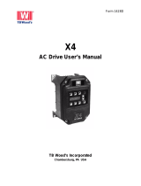
Figure 2-1 explains the base drive part number used to derive the drive code
printed on the nameplate, located at on the right side of the enclosure, or
inside the door of the ACS 502, or on the left side below the brake terminals
on the ACS 504.

Chapter 2 – Overview of the ACS 502/504
2-2 ACS 502 Installation & Start-up Manual
Figure 2-1 Explanation of ACS 502/504 Drive Code
ACS 502 - 075 - 4 - 0 0 P 2
AC = AC Drive
Product Type:
S = Standard Product
Family:
50 = ACS 500
Construction
1 = Sizes 002 to 060, Wall Mounted
2 = Sizes 050 to 350, Std Floor Stand Cabinet
4 = Sizes 050 to 350, Module
Output Power (HP, Constant Torque)
Input Voltage
3 = 380-415 VAC
4 = 440-500 VAC
Internal Option 2
0 = No Option
Internal Option 1
2 = I/O Extension Board (SNAT 7520 IOE)
8 = (5) Isolated Digital Inputs (SNAT 763 DII)
9 = 3-15 PSI and (2) Isolated Digital Inputs (SNAT 762 PSI)
0 = No Option
Control Panel
P = Internal Control Panel (Keypad and Display)
0 = No Panel
Protection Class of Enclosure*
0 = Chassis (IP 00)
2 = NEMA 1 (IP 21)
3 = NEMA 1 w/Air Filters
5 = NEMA 12 (IP 54)
*Not all Protection Classes are available for all units.
A = 115 VAC Control Power Board
Dynamic Braking
Blanks = No Brake
1 = Internal Dynamic Brake Chopper Installed
(KVA, Constant Torque for 380 VAC)
6 = 525-600 VAC
3 = Tachometer input option (SNAT 7610 BAC)

Chapter 2 – Overview of the ACS 502/504
ACS 502 Installation & Start-up Manual 2-3
Types and Ratings of
the ACS 502/504
Table 2-1 shows the type series and ratings of the ACS 504.
Table 2-1 Rating Table for ACS 502 and ACS 504, 440 – 500 VAC,& 525 – 600 VAC
Drive Type
Constant Torque Variable Torque
I
N
Dimension
Reference
hp
Amps
(Current Rating
of Drive)
hp
Amps
(Current Rating
of Drive)
I
R
I
IN
I
RSQ
I
INSQ
480 volt units
ACS50X-050-4- 50 65 62 60 77 69 65
R6ACS50X-060-4- 60 77 71 75 96 87 84
ACS50X-075-4- 75 96 87 100 124 111 112
ACS50X-100-4- 100 124 113 125 156 141 135
R7
ACS50X-125-4- 125 156 143 150 180 159 164
ACS50X-150-4- 150 180 161 200 240 214 200
R8
ACS50X-200-4- 200 240 218 250 302 269 240
ACS50X-250-4- 250 302 273 300 361 328 300
R9ACS50X-300-4- 300 361 333 350 414 376 365
ACS50X-350-4- 300 361 333 400 460 418 365
600 volt units
ACS50X-060-6- 60 62 54 75 77 67 77
R6
ACS50X-075-6- 75 77 67 100 99 87 77
ACS50X-100-6- 100 99 87 125 125 110 99 R7
ACS50X-125-6- 125 125 110 150 144 126 125 R8
ACS50X-150-6- 150 144 126 200 192 168 172 R9

Chapter 2 – Overview of the ACS 502/504
2-4 ACS 502 Installation & Start-up Manual
Table 2-2 shows the definitions for symbols used in this manual.
Table 2-2 Symbol Definitions
ACS 502 Control
Identification
The numbers and letters in the last seven spaces of the ACS 502 Model
Number stand for the specific options included with your drive. Locate the
Control Nameplate on the right side of the enclosure or inside the door of the
ACS 502 and use Figure 2-2 to verify the options included with your drive.
The first part of the part number is derived from Figure 2-1 by removing the
letters AC in the first two places and the dashes (-).
Symbol Definition
V
IN
Rated supply voltage [V]. The actual voltage is set by a parameter.
I
IN
Approximate input current (rms) when shaft power is P
R
, line voltage is 480 V, and the motor is a standard NEMA
motor [Amps].
I
R
Rated output current in constant torque applications [Amps].
P
R
Maximum motor nominal shaft power in constant torque applications for 2-, 4-, and 6-pole standard motors [hp].
I
INSQ
Approximate input current when shaft power is P
RSQ
, line voltage is 480 V and the motor is a standard NEMA
motor. This is the maximum thermal input current [Amps].
I
RSQ
Rated output current in squared torque applications [Amps].
P
RSQ
Maximum motor nominal shaft power in squared torque applications for 2-, 4-, and 6-pole standard motors [hp].
I
N
The output current on which the drive’s internal trips and settings are based [Amps].

Chapter 2 – Overview of the ACS 502/504
ACS 502 Installation & Start-up Manual 2-5
Figure 2-2 Nameplate Codes
MOL
ACS 502
A=29.3 to 32.0
B=32.1 to 34.9
C=35.0 to 37.8
D=37.9 to 41.7
E=41.8 to 45.9
F=46.0 to 49.0
G=49.1 to 54.2
H=54.3 to 60.0
J=57.1 to 62.8
K=62.9 to 69.1
L=69.2 to 75.0
M=75.1 to 83.3
N=83.4 to 86.9
P=87.0 to 92.9
Q=93.0 to 100
R=98 to 107.9
S=108 to 113.9
T=114 to 125.9
U=126 to 138.9
V=139 to 153
W=154 to 163
X=164 to 180
Y=175 to 194
Z=195 to 220
2=221 to 247
3=248 to 276
4=277 to 307
5=308 to 345
6=346 to 381
7=382 to 420
8=421 to 465
0=None
ACS502-075-4-00P2
S502075400P2
NEMA Type Enclosure
2=NEMA 1
3=NEMA 1 with Air Filters
5=NEMA 12
Control
A=Hand-Off-Auto Switch incl. 115 V
Control Transformer
B=Hand-Off-Auto Switch & Speed Pot
incl. 115 V Control Transformer
C=115 VAC Control Transformer
& Terminal Board
1=Internal Brake Chopper
M=A+1
N=B+1
P=C+1
0=None
Input Options
A=Door Interlocked Disconnect Switch
B=Door Interlocked Circuit Breaker
C=Disconnect w/3% Line Reactor
D=Circuit Breaker w/3% Line Reactor
E=Input Terminal Block w/3% Line
Reactor
F=Disconnect w/5% Line Reactor
G=Circuit Breaker w/5% Line Reactor
H=Input Terminal Block w/5% Line
Reactor
0=Extended Enclosure w/Input
Terminal Block
Bypass
A=Manual Bypass
B=Manual Bypass w/Service Switch
C=Automatic Bypass
D=Automatic Bypass w/Service Switch
E=Manual Bypass, Mechanically
Interlocked
F=Manual Bypass w/Service Switch,
Mechanically Interlocked
G=Automatic Bypass, Mechanically
Interlocked
H=Automatic Bypass w/Service
Switch, Mechanically Interlocked
0=None
Meters
A=Analog Voltmeter
B=Analog Speed Meter
Y=Ammeter (Sized to unit)
Z=Two Ammeters (Sized to MOL’s)
1=A+B
2=A+Y
3=A+Z
4=B+Y
5=B+Z
6=A+B+Y
7=A+B+Z
0=None
* Horsepowers listed are estimated only.
MOL’s MUST be sized for the specific motor.
25
30
40
50
60
75
100
125
150
200
250
300
350
HP*

Chapter 2 – Overview of the ACS 502/504
2-6 ACS 502 Installation & Start-up Manual
General Information
About Your ACS 502/504
Functional Description
Power-on sequence
When line voltage is switched on, the capacitor bank is charged first via the
charging circuit. The charging takes less than one second. During this time,
the thyristors on the rectifier bridge are not conducting.
GENERAL WARNING! The maximum permissible number of chargings in
one minute is four. If the DC bus is charged more often, the charging resistor
may fail due to excess heat. Therefore, it is recommended that you do not use
the input power switching on and off as a Start/Stop command.
The power supply of the ACS 504 comes from the capacitor bank. The power
supply turns on when the voltage on the capacitors has reached about
300 VDC. Subsequently, the Control Interface Card, Motor Control Card and
Main Circuit Interface Card are energized.
When the DC-voltage has reached 80% of its nominal value, the
microprocessor on the Motor Control Card energizes the Input Protection
Card. The thyristors are gated fully conducting and the thyristor-diode
rectifier behaves like a normal 6-pulse diode bridge.
The cooling fan turns on at initial power-on. To prolong the useful life of the
fan bearings, the fan is automatically turned off after one minute, unless:
• The drive has a RUN command, or
• Heatsink temperature is above 113°F (45°C).
Control
In normal duty the drive follows commands and references either from the
keypad or the terminal block on the Control Interface Card. The control signal
source selection and the way the drive interprets these signals are configured
by parameters.
Power section
Power flow through the drive in normal duty is from AC-input line through
the rectifier bridge to the DC-filter capacitors which sustain a constant DC-
voltage. The nominal value for this voltage is 1.35 x V
IN
.
The Inverter consists of six power semiconductor switches whose operation is
controlled by the Motor Control Card via the Main Circuit Interface Card.
Turning these switches on and off in a certain sequence is called modulation.
The modulation frequency in the ACS 504 is about 3 kHz at maximum and
cannot be altered.
The potential at any terminal U
2
, V
2
, W
2
(T
1
, T
2
, T
3
) of the inverter can only
be high or low. The modulation determines which one. At any instant, the line
to line output voltage is either 0 V when the switches in these phases are in the
same position or ± 1.35 x V
IN
when the corresponding switches are in
different positions.
/