Page is loading ...

ROUTER TABLE WITH ROUTER
Model
95380
SET UP AND OPERATING INSTRUCTIONS
Visit our website at: http://www.harborfreight.com
Read this material before using this product.
Failure to do so can result in serious injury.
SAVE THIS MANUAL.
Copyright
©
2006 by Harbor Freight Tools
®
. All rights reserved. No portion of this manual or any artwork
contained herein may be reproduced in any shape or form without the express written consent of
Harbor Freight Tools. Diagrams within this manual may not be drawn proportionally. Due to continuing
improvements, actual product may differ slightly from the product described herein. Tools required for
assembly and service may not be included.
For technical questions or replacement parts, please call 1-800-444-3353.
Manual Revised 11c

SKU 95380 For technical questions, please call 1-800-444-3353 PAGE 2
SPECIFICATIONS
Motor 110 VAC / 60 Hz / 11 A / 1-3/4 HP / 20,000 Maximum RPM
Router Type Plunge Router with Brake
Router Power Cord SJT 16 AWG x 2C
Router Table Power Switch Rocker (ON/OFF) with Safety Key
Router Table Power Cord 16 AWG 3C
Router Table Power Plug 3-Prong / Grounded
Router Collet Sizes 1/2” with 3/8” & 1/4” Adapters
Router Depth Scale 1” to 3” in 1/16” Increments
Miter Gauge Dimensions 5-1/2” Long x 3” Wide x 1-1/2” High
Miter Gauge Capacity 0° to 60° (Left & Right)
Table Dust Port Dimensions 1-3/8” Outside Diameter
Table Top Dimensions 14-3/8” Long x 23-3/4” Wide x 3/4” Thick
Overall Dimensions 14-13/16” Long x 23-3/4” Wide x 15-3/4” High
Additional Features 19 Gauge Steel Legs / Clear Plastic Guard
Weight 20 Pounds
SAVE THIS MANUAL
You will need this manual for the safety warnings and precautions,
assembly, operating, inspection, maintenance and cleaning procedures,
parts list and assembly diagram. Keep your invoice with this manual.
Write the invoice number on the inside of the front cover. Keep this
manual and invoice in a safe and dry place for future reference.
GENERAL SAFETY RULES
WARNING! Read all instructions
Failure to follow all instructions listed below may result in electric shock,
re, and/or serious injury. The term “power tool” in all of the warnings listed
below refers to your mains-operated (corded) power tool or battery-operated
(cordless) power tool.
SAVE THESE INSTRUCTIONS
WORK AREA
1. Keep your work area clean and well lit. Cluttered
benches and dark areas invite accidents.
2. Do not operate the Router in explosive atmospheres, such as
in the presence of ammable liquids, gases, or dust. Power
equipment creates sparks which may ignite the dust or fumes.
3. Keep bystanders, children, and visitors away while operating power
equipment. Distractions can cause you to lose control. Protect others in
the work area from debris such as chips and sparks. Provide barriers or
shields as needed. Children and visitors should never be in the work area.
227847

SKU 95380 For technical questions, please call 1-800-444-3353 PAGE 3
ELECTRICAL SAFETY
1. Grounded tools must be plugged into an outlet properly installed
and grounded in accordance with all codes and ordinances. Never
remove the grounding prong or modify the plug in any way. Do
not use any adapter plugs. Check with a qualied electrician if you
are in doubt as to whether the outlet is properly grounded. If the
tools should electrically malfunction or break down, grounding provides
a low resistance path to carry electricity away from the user.
2. Avoid body contact with grounded surfaces such as
pipes, radiators, ranges, and refrigerators. There is an
increased risk of electric shock if your body is grounded.
3. Do not expose power tools to rain or wet conditions. Water
entering power equipment will increase the risk of electric shock.
4. Do not abuse the Power Cord. Never use the Power Cord to pull
the Plug from an outlet. Keep the Power Cord away from heat, oil,
sharp edges, or moving parts. Replace damaged Power Cords
immediately. Damaged Power Cords increase the risk of electric shock.
PERSONAL SAFETY
1. Stay alert. Watch what you are doing, and use common sense when
operating the Router. Do not use the tool while tired or under the
inuence of drugs, alcohol, or medication. A moment of inattention
while operating power tools may result in serious personal injury.
2. Dress properly. Do not wear loose clothing or jewelry. Contain long
hair. Keep your hair, clothing, and gloves away from moving parts.
Loose clothes, jewelry, or long hair can be caught in moving parts.
3. Use the right product for the job. Do not attempt to force small equipment
to do the work of larger industrial equipment. There are certain applications
for which this product was designed. It will do the job better and safer at
the rate and capacity for which it was designed. Do not modify this product,
and do not use this product for a purpose for which it was not designed.
4. Avoid accidental starting. Be sure the Power Switch is off before plugging
in. Plugging in power equipment with the Power Switch on, invites accidents.
5. Remove adjusting keys or wrenches before turning the
power tool on. A wrench or a key that is left attached to a
rotating part of the Router may result in personal injury.
6. Do not overreach. Keep proper footing and balance at all times. Proper
footing and balance enables better control of the Router in unexpected situations.

SKU 95380 For technical questions, please call 1-800-444-3353 PAGE 4
7. Use safety equipment. Always wear ANSI-approved safety impact
eye goggles. Dust mask or respirator, and hearing protection must be
used for appropriate conditions.
TOOL USE AND CARE
1. Do not force the Router. Use the correct tool for your application. The
correct tool will do the job better and safer at the rate for which it is designed.
2. Do not use the Router if the Power Switch does not turn
it on or off. Any tool that cannot be controlled with the
Power Switch is dangerous and must be replaced.
3. Disconnect the Power Cord Plug from the power source before making
any adjustments, changing accessories, or storing the Router. Such
preventive safety measures reduce the risk of starting the tool accidentally.
4. Store idle tools and equipment out of reach of children and other untrained
persons. Tools and equipment are dangerous in the hands of untrained users.
5. Maintain this product with care. Keep the Router and its Table clean
and in proper working order. Properly maintained tools and equipment
are easier to control. Do not use damaged tools and equipment. Tag
damaged tools and equipment “Do not use” until repaired.
6. Check for misalignment or binding of moving parts, breakage
of parts, and any other condition that may affect the Router’s
operation. If damaged, have the tool serviced before using.
Many accidents are caused by poorly maintained tools.
7. Use only accessories that are recommended by the manufacturer
for your model. Accessories that may be suitable for one product
may become hazardous when used on another product.
SERVICE
1. Tool service must be performed only by qualied repair personnel. Service
or maintenance performed by unqualied personnel could result in a risk of injury.
2. When servicing a tool, use only identical replacement parts. Follow
instructions in the “Inspection, Maintenance, And Cleaning”
section of this manual. Use of unauthorized parts or failure to follow
maintenance instructions may create a risk of electric shock or injury.

SKU 95380 For technical questions, please call 1-800-444-3353 PAGE 5
SPECIFIC SAFETY RULES
1. Maintain labels and nameplates on the Router and its Table.
These carry important information. If unreadable or missing,
contact Harbor Freight Tools for a replacement.
2. Avoid unintentional starting. Make sure you are prepared
to begin work before turning on the Router.
3. Do not force the Router. This tool will do the work better and
safer at the speed and capacity for which it was designed.
4. This Router is designed for use only with 1/2” Router Bits and
3/8” and 1/4” Adapters rated at 20,000 RPM or greater.
5. WARNING! Keep hands and ngers away from the cutting area and
Router Bit (not included). Use a “push stick” (not included) when necessary.
6. Make sure the Router Table is securely attached to a dry,
at, level, sturdy workbench surface capable of supporting
the weight of the unit, accessories, and workpieces.
7. Never leave the Router Table unattended when it is plugged into an
electrical outlet. Always unplug the unit from its electrical outlet before leaving.
8. Industrial applications must follow OSHA guidelines.
9. Never stand on the Router Table. Serious injury could result if the unit is tipped.
10. Always unplug the Router Table from its power supply source before
performing any inspection, maintenance, or cleaning procedures.
11. Keep all guards in place and in proper working order.
12. Allow the Router Bit (not included) to spin up to full speed before feeding
a workpiece into the Bit. When turning off the Router, allow the Bit to
spin down and stop on its own. Do not press against the Bit to stop it.
13. Turn off the Router and allow the Router Bit (not included) to stop on
its own if the workpiece is to be backed out of an uncompleted cut.
14. Never attempt to remove material stuck in the moving parts
of the Router while it is plugged in and running.
15. When routing a large workpiece, make sure its entire length is properly
supported. If necessary, use a roller stand (not included) with larger workpieces.
16. Never attempt to cut freehand. Make sure the workpiece
to be cut is pressed rmly against the Table’s Fence.

SKU 95380 For technical questions, please call 1-800-444-3353 PAGE 6
17. Never cut pieces too small to be held securely against the
Table’s Fence without leaving enough space for the hand to
be a safe distance from the Router Bit (not included).
18. Make sure the Table and surrounding area are clear
with the exception of the workpiece to be cut.
19. Before each use of the Router, make sure it is
securely attached to the Router Table.
20. The Router Table is designed for cutting at workpieces
only. Do not attempt to cut workpieces that are not at.
21. The Router and Router Table are designed for cutting
wood workpieces only. Do not attempt to use the Router
and its Table to cut metal or other non-wood materials.
22. Never attempt to cut more than one workpiece at a time.
23. Always make sure the work surface of the Router Table is
clean and free of dust, wood chips, and other debris that
can interfere with the cut you are going to make.
24. Always keep children and other unauthorized people away
from the Router Table. Unplug the Table, and remove the
Power Switch’s Safety Key when the Table is not in use.
25. Never reach under the Router Table for any
reason when the Router is running.
26. Avoid overloading the Router. If the speed drops abnormally,
decrease the pressure on the workpiece immediately.
27. Use the right tool for the job. Do not attempt to force a small tool or
attachment to do the work of a larger industrial tool. There are certain
applications for which this tool was designed. It will do the job better and
more safely at the rate for which it was intended. Do not modify this tool,
and do not use this tool for a purpose for which it was not intended.
28. Always use sharp Router Bits (not included). If the Bit stops
abruptly, or the Bit becomes blocked, turn the Router Table’s
Power Switch to its “OFF” position immediately.
29. Before routing, run the Router for about ten seconds to ensure
all moving parts are running smoothly and there are no loose
parts, rattles, or sparking that would indicate damage.
30. WARNING! Some dust created by power sanding, sawing, grinding, drilling,
and other construction activities, contain chemicals known (to the State of
California) to cause cancer, birth defects or other reproductive harm. Some

SKU 95380 For technical questions, please call 1-800-444-3353 PAGE 7
examples of these chemicals are: lead from lead-based paints, crystalline silica
from bricks and cement or other masonry products, arsenic and chromium from
chemically treated lumber. Your risk from these exposures varies, depending on
how often you do this type of work. To reduce your exposure to these chemicals:
work in a well ventilated area, and work with approved safety equipment, such as
those dust masks that are specially designed to lter out microscopic particles.
(California Health & Safety Code § 25249.5, et seq.)
31. People with pacemakers should consult their physician(s) before
use. Electromagnetic elds in close proximity to heart pacemaker
could cause pacemaker interference or pacemaker failure.
32. WARNING! The warnings and cautions discussed in this manual cannot
cover all possible conditions and situations that may occur. It must be under-
stood by the operator that common sense and caution are factors which
cannot be built into this product, but must be supplied by the operator.
SAVE THESE INSTRUCTIONS
GROUNDING
Improperly connecting the grounding
wire can result in electric shock.
Check with a qualied electrician if you are in doubt as to
whether the outlet is properly grounded. Do not modify the
power cord plug provided with the tool. Never remove the
grounding prong from the plug. Do not use the tool if the
power cord or plug is damaged. If damaged, have it repaired
by a service facility before use. If the plug will not t the
outlet, have a proper outlet installed by a qualied electrician.
Grounded Tools: Tools with Three Prong Plugs
1. Tools marked with “Grounding Required” have a three wire cord and three
prong grounding plug. The plug must be connected to a properly grounded
outlet. If the tool should electrically malfunction or break down, grounding
provides a low resistance path to carry electricity away from the user,
reducing the risk of electric shock. (See 3-Prong Plug and Outlet.)
2. The grounding prong in the plug is connected through the green wire inside
the cord to the grounding system in the tool. The green wire in the cord must
be the only wire connected to the tool’s grounding system and must never be
attached to an electrically “live” terminal. (See 3-Prong Plug and Outlet.)
WARNING

SKU 95380 For technical questions, please call 1-800-444-3353 PAGE 8
3. The tool must be plugged into an appropriate outlet, properly installed and
grounded in accordance with all codes and ordinances. The plug and outlet
should look like those in the following illustration.
(See 3-Prong Plug and Outlet.)
THE
ROUTER TABLE
POWER CORD
USES A
3-PRONG PLUG
3-Prong Plug and Outlet
Outlets for 2-Prong Plug
Double Insulated Tools: Tools with Two Prong Plugs
1. Tools marked “Double Insulated” do not require grounding. They have a special
double insulation system which satises OSHA requirements and complies
with the applicable standards of Underwriters Laboratories, Inc., the Canadian
Standard Association, and the National Electrical Code.
(See Outlets for 2-Prong Plug.)
2. Double insulated tools may be used in either of the 120 volt outlets
shown in the preceding illustration. (See Outlets for 2-Prong Plug.)
Symbology
Double Insulated
V~
Volts Alternating Current
Canadian Standards Association
A
Amperes
Underwriters Laboratories, Inc.
n
0
xxxx/min.
No Load Revolutions
per Minute (RPM)
UNPACKING
When unpacking, check to make sure all the parts shown on the Parts List on
pages 16 and 17 are included. If any parts are missing or broken, please call Harbor
Freight Tools at the number shown on the cover of this manual as soon as possible.

SKU 95380 For technical questions, please call 1-800-444-3353 PAGE 9
ASSEMBLY INSTRUCTIONS
Note: For additional information regarding the parts listed in the following
pages, refer to the Assembly Diagram on pages 16 and 17.
CAUTION! Always make sure the Power Switch (2B) of the
Router Table is in its “OFF” position and the unit is unplugged from
its electrical outlet prior to performing any assembly procedures.
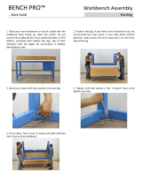
To Attach the Legs to the Table:
1. Carefully turn the Router Table (5B) upside down.
2. Insert a Machine Screw (25B) through each of the 16 holes indicated with
an arrow in Figure A, below. Insert them so that the heads are near the top
of the table and the threads stick out to allow the Legs to be attached.
Figure A - Insert Machine Screws (25B)
upwards through the Table.
Table (5B)
Legs (1B)
3. Each Leg (1B) has four holes at its top. Place those holes
over the ends of the Screws as shown in Figure A.
4. Secure the Legs to the Screws using the Spring Lock
Washers (17B) and Nuts (18B). Tighten securely.
REV 11c

SKU 95380 For technical questions, please call 1-800-444-3353 PAGE 10
To Mount The Router Table On A Workbench:
1. CAUTION! Make sure the Router Table is securely attached
to a dry, at, level, sturdy workbench surface capable of supporting
the weight of the unit, accessories, and workpieces.
2. At the bottom of each of the four Legs (1B) of the Router Table are
two 1/4” diameter mounting holes. (See Assy. Diagram B.)
3. With assistance, place the Router Table in the desired location on the workbench.
Then use the mounting holes (eight total) in the Legs (1B) as a template to
mark where eight 1/4” diameter holes are to be drilled through the workbench.
4. Temporarily remove the Router Table from the workbench. Then, using
a 1/4” drill bit (not included), drill the pre-marked holes through the
workbench. Always check for hidden obstructions in the drilling path.
5. Place the Router Table back on the workbench and align the mounting
holes in its Legs (1B) with the pre-drilled holes in the workbench.
6. Secure the Router Table to the workbench, using eight 1/4” diameter Bolts of
appropriate length, eight Lock Washers, and eight Nuts (none included).
To Install The Miter Gauge:
Figure B
GUIDING GROOVE
(4B)
MITER GAUGE
(12B)
Make sure the Guiding Groove (4B) on the Worktable (5B) top is clean and free
of all debris. Then, insert the Miter Bar of the Miter Gauge (12B) in the groove.
Slide the Miter Gauge assembly forward and backward in the
groove to ensure proper installation. (See Figure B.)

SKU 95380 For technical questions, please call 1-800-444-3353 PAGE 11
To Connect A Vacuum Hose To The Dust Port:
Figure C
DUST PORT
(1-3/8” OUTSIDE DIAMETER)
The Dust Port of the Router Table is 1-3/8” O.D. (outside diameter) and is located
at the rear of the Router Table. Use an automotive hose clamp (not included) to
secure an appropriate size vacuum hose (not included) to the Dust Port.
(See Figure C.)
The Router Table Power Switch/Outlets Assembly:
1.
SAFETY KEY
POWER SWITCH
Figure D
The Power Switch/Outlets (2B) assembly is equipped with a Safety Key
to help prevent unauthorized use of the Router Table. (See Figure D.)
2. To provide power to the Router Table, connect the Power Cord/Plug of the
Power Switch/Outlets assembly to the nearest 110 volt, grounded, electrical
outlet. Insert the Safety Key into the Power Switch (2B), and pull up on the
Power Switch to provide power to the Router Table (and Router). To shut off
power to the Router Table (and Router), push down on the Power Switch and
remove the Safety Key. Make sure to store the Safety Key in a safe location,
out of reach of children and other unauthorized people. (See Figure D.)
3. The Power Switch/Outlets (2B) assembly also provides two 110
volt, grounded, electrical outlets with which to provide electrical
power to the Router and/or another electrically powered tool.

SKU 95380 For technical questions, please call 1-800-444-3353 PAGE 12
To Install A Router Bit:
1. WARNING! Make sure the Power
Switch of the Router Table is in its
“OFF” position and the Router Table is
not plugged into an electrical outlet.
2. Fully insert the Router Bit (not included)
into the Collet Chuck (5A). Firmly tighten
the Collet Chuck with the two accessory
Wrenches (10B, 11B). (See Figure E.)
To Adjust The Depth Of The Cut:
1.
ROUTER TABLE
POWER SWITCH
&
OUTLETS
DEPTH
ROD (18A)
KNOB (12A)
Figure F
Loosen the Lock Lever (8A). Then, loosen the Knob (12A).
(See Figure F and Assy. Diagram A.)
2. Adjust the Router to obtain the required cutting
depth. Then, retighten the Lock Lever.
3. Adjust the Depth Rod (18A) on the Router to read “0” when the router bit is
ush with the table top. Check to make sure that even if released with the
Lock Lever, the Router stops at the determined depth for repeated cuts.
Note: Minute depth adjustments (in 1/16” increments) can be made by raising or
lowering the Depth Rod (18A). (See Figure F and Assy. Diagram A.)
COLLET CHUCK
(5A)
Figure E
WRENCH
(10B)
WRENCH
11B)

SKU 95380 For technical questions, please call 1-800-444-3353 PAGE 13
BASIC OPERATING INSTRUCTIONS
WARNING! Use safety equipment. Always wear ANSI-
approved safety impact eye goggles. Dust mask or respirator,
and hearing protection must be used for appropriate conditions.
1. Make sure the Power Switch of the Router Table is in its “OFF” position
and the Table is not plugged into an electrical outlet. Then, install a
Router Bit (not included) onto the Router and adjust its cutting depth.
2. Make all necessary adjustments to the Router Table’s Fence (6B),
Adjustable Fence (9B), and Miter Gauge (12B) depending on the
cut(s) to be made to the workpiece. Also, check to make sure
the retractable Guard (8B) is in proper working order.
3. Check to make sure the Router Table’s Power Switch/Outlets (2B) assembly
is in its “OFF” position. Then connect the Router Table’s Power Switch/
Outlets assembly into the nearest 110 volt, grounded, electrical outlet.
4. Note: Before rst use of the Router on a workpiece it is recommended
that you test and practice with the Router using a scrap workpiece.
5. Insert the Safety Key of the Router Table’s Power Switch/Outlets (2B), and pull
up on the Power Switch to provide power to the Router Table and Router.
6. Make sure to hold the workpiece rmly against the Router Table’s
Stationary Fence (6B), Adjustable Fence (9B), and Miter Gauge
(12B) depending on the cut(s) to be made to the workpiece.
7. Allow the Bit of the Router to rotate up to full speed, then feed the workpiece
gradually from right to left against the rotation of the Bit. Keep the feed
rate constant. Feeding the workpiece too quickly will slow the motor of the
Router. Feeding the workpiece too slowly will cause burns to the workpiece.
8. On very hard wood or large cuts it may be necessary to make more than one
pass at progressive depth settings until the desired depth of cut is made.
9. When nished, remove the workpiece from the Router Table. Turn the Power
Switch/Outlets (2B) assembly to its “OFF” position and remove the Safety Key.
Then, disconnect the Power Switch/Outlets assembly from its electrical outlet.
10. Allow sufcient time for the Router Bit to stop rotating and also to
completely cool before removing the Bit from the Router.
11. Always store the Router and Router Table in a clean, dry, safe
location out of reach of children and other unauthorized people.

SKU 95380 For technical questions, please call 1-800-444-3353 PAGE 14
TROUBLESHOOTING
Problem Possible Solution
Router will not run. 1. Make sure the Power Switch of the Router Table is in its “ON” position.
2. Make sure the Power Switch of the Router is in its “ON” position.
3. Make sure the Power Cord of the Router is
connected to the Power Table’s Outlet.
4. Make sure the Power Cord of the Router Table is connected
to a working, 110 volt, grounded, electrical outlet.
5. Check the Power Cords of the Router and Router Table for damage.
6. Carbon brushes need replacing.
7. Have a qualied service technician check the
Router and Router Table for defects.
Excessive vibration
when Router is on.
1. Make sure the Router is properly and rmly attached to the Router Table.
2. Make sure the Bit in the Router is sharp and properly
installed. Make sure Bit is not bent or damaged.
3. Have a qualied service technician check the
Router and Router Table for defects.
The Power Switch
of the Router and/
or Router Table does
not turn off the tool.
Immediately unplug the Router Table’s Power Cord from its
electrical outlet. Discontinue using tool until a qualied service
technician checks the Router and Router Table for defects.

SKU 95380 For technical questions, please call 1-800-444-3353 PAGE 15
INSPECTION, MAINTENANCE, AND CLEANING
1. CAUTION! Always make sure the Power Switch of the Router Table is in
its “OFF” position and the Router Table is unplugged from its electrical outlet
prior to performing any inspection, maintenance, or cleaning procedures.
2. Before each use, inspect the general condition of the Router and Router
Table. Check for misalignment or binding of moving parts, cracked or
broken parts, damaged electrical wiring, and any other condition that may
affect their safe operation. If abnormal noise or vibration occurs, have the
problem corrected before further use. Do not use damaged equipment.
3. To clean the exterior of the Router and Router Table, use only a clean cloth
and mild detergent. Do not immerse any part of the unit in liquid.
4. To clean or replace the Carbon Brushes (32A): It may become necessary
to clean or replace the two Carbon Brushes when the Motor performance
decreases, or stops working completely. The Carbon Brushes are located
on each side of the Motor Housing (36A). To do so, remove the two Brush
Holders (31A). Then, remove the two Carbon Brushes from the Brush Holders.
If the Carbon Brushes are worn down more than 1/2, replace both Carbon
Brushes. If, however, the Carbon Brushes are just dirty they may be cleaned
by rubbing them with a pencil eraser. When installing the Carbon Brushes,
make sure brushes are in the same position and direction as before they were
removed. Make sure the carbon portion of the Carbon Brushes contact the
Stator (23A) assembly and the springs face away from the Motor. Also, make
sure the springs operate freely. After cleaning or replacement, replace the Brush
Holders.
NOTE: New Carbon Brushes tend to arc or spark when rst used until
they wear and conform to the Stator assembly. (See Assy. Diagram.)
5. CAUTION! All maintenance, service, or repairs not mentioned in
this manual must only be performed by a qualied service technician.
PLEASE READ THE FOLLOWING CAREFULLY
THE MANUFACTURER AND/OR DISTRIBUTOR HAS PROVIDED THE PARTS LIST AND ASSEMBLY
DIAGRAM IN THIS MANUAL AS A REFERENCE TOOL ONLY. NEITHER THE MANUFACTURER OR
DISTRIBUTOR MAKES ANY REPRESENTATION OR WARRANTY OF ANY KIND TO THE BUYER THAT HE
OR SHE IS QUALIFIED TO REPLACE ANY PARTS OF THE PRODUCT. IN FACT, THE MANUFACTURER
AND/OR DISTRIBUTOR EXPRESSLY STATES THAT ALL REPAIRS AND PARTS REPLACEMENTS
SHOULD BE UNDERTAKEN BY CERTIFIED AND LICENSED TECHNICIANS, AND NOT BY THE BUYER.
THE BUYER ASSUMES ALL RISKS AND LIABILITY ARISING OUT OF HIS OR HER REPAIRS TO THE
ORIGINAL PRODUCT OR REPLACEMENT PARTS THERETO, OR ARISING OUT OF HIS OR HER
INSTALLATION OF REPLACEMENT PARTS THERETO.

SKU 95380 For technical questions, please call 1-800-444-3353 PAGE 16
PARTS LISTS & ASSEMBLY DIAGRAMS
PARTS LIST & ASSEMBLY DIAGRAM A - ROUTER
Part Description Qty.
1A Machine Screw 2
2A Template Guide 1
3A Base Assy. 1
4A Nut Clamp 1
5A Collet Chuck 1
6A Lock Piece 1
7A Lock Screw 1
8A Lock Lever 1
9A E-Type Retaining Ring 2
10A Machine Screw 1
11A Handle 1
12A Knob 1
13A End Bracket Assy. 1
14A Ball Bearing 1
15A Bearing Cover 1
16A Flat Head Screw 3
17A Spring 2
18A Depth Rod 1
Part Description Qty.
19A Insulator 1
20A Tapping Screw 2
21A Washer 2
22A Armature 1
23A Stator Assy. 1
24A Ball Bearing 1
25A Bearing Bushing 1
26A End Cover 1
27A Tapping Screw 2
28A Tapping Screw 4
29A Teeterboard 4
30A Peg 2
31A Brush Holder 2
32A Carbon Brush 2
33A Brush Cap 2
34A Power Cord 1
35A Line Lock 1
36A Motor Housing 1
NOTE:
Some parts are listed and shown for illustration purposes only,
and are not available individually as replacement parts.

SKU 95380 For technical questions, please call 1-800-444-3353 PAGE 17
PARTS LIST & ASSEMBLY DIAGRAM B - ROUTER TABLE
Part Description Qty.
1B Leg 4
2B Power Switch/Outlets 1
3B Fixed Stand 1
4B Guiding Groove 1
5B Work Table 1
6B Fence 1
7B Knob 3
8B Guard 1
9B Adjustable Fence 1
10B Wrench (21mm) 1
11B Wrench (24mm) 1
12B Miter Gauge 1
13B Chuck Sleeve (1/4”) 1
Part Description Qty.
14B Chuck Sleeve (1/2”) 1
15B Chuck Sleeve (3/8” 1
16B Machine Screw 2
17B Spring Lock Washer 23
18B Nut 23
19B Metal Gasket 10
20B Flat Head Screw 3
21B Dust Cover 1
22B Machine Screw 3
23B Torsion Spring 1
24B Tapping Screw 1
25B Machine Screw 18
26B Spacing Pin 1

SKU 95380 For technical questions, please call 1-800-444-3353 PAGE 18
LIMITED 90 DAY WARRANTY
Harbor Freight Tools Co. makes every effort to assure that its products meet
high quality and durability standards, and warrants to the original purchaser that this
product is free from defects in materials and workmanship for the period of 90 days
from the date of purchase. This warranty does not apply to damage due directly or
indirectly, to misuse, abuse, negligence or accidents, repairs or alterations outside
our facilities, criminal activity, improper installation, normal wear and tear, or to lack of
maintenance. We shall in no event be liable for death, injuries to persons or property,
or for incidental, contingent, special or consequential damages arising from the use
of our product. Some states do not allow the exclusion or limitation of incidental or
consequential damages, so the above limitation of exclusion may not apply to you. THIS
WARRANTY IS EXPRESSLY IN LIEU OF ALL OTHER WARRANTIES, EXPRESS OR
IMPLIED, INCLUDING THE WARRANTIES OF MERCHANTABILITY AND FITNESS.
To take advantage of this warranty, the product or part must be returned to
us with transportation charges prepaid. Proof of purchase date and an explanation
of the complaint must accompany the merchandise. If our inspection veries
the defect, we will either repair or replace the product at our election or we may
elect to refund the purchase price if we cannot readily and quickly provide you
with a replacement. We will return repaired products at our expense, but if we
determine there is no defect, or that the defect resulted from causes not within the
scope of our warranty, then you must bear the cost of returning the product.
This warranty gives you specic legal rights and you may
also have other rights which vary from state to state.
3491 Mission Oaks Blvd. • PO Box 6009 • Camarillo, CA 93011 • (800) 444-3353
/