
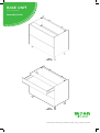
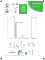
BASE UNIT
1000 2/3 Drawer
Assembly Guide
For Internal Use: FI.WR.INS.027_WKIN00111_BASE_1000_2_3Drawer_Rev4.indd
1000
2 Drawer
1000
3 Drawer

BASE UNIT
1000 2/3 Drawer
Assembly Guide
For Internal Use: FI.WR.INS.027_WKIN00111_BASE_1000_2_3Drawer_Rev4.indd
Page 1
BASE UNIT
1000 32/3 Drawer
Drawer Assembly
BEFORE YOU START
INSTALLATION
SHOULD BE
PERFORMED BY A
COMPETENT
PERSON ONLY.
THIS PRODUCT COULD
BE DANGEROUS
IF INCORRECTLY
INSTALLED
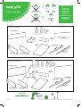
REQUIRED TOOLS
NOT to be used
with CAM DOWEL
& CAM LOCK
Standard Drawer (Packed Separately)
Fitting Pack Contents
Drawer
Cover Cap
x2
Drawer
Cover Cap
x2
Frontal
(Supplied Separately
Metal Back Panel
x 1
Drawer Side
x1 Right Hand
Drawer Side
x1 Right Hand
Drawer Side
x1 Left Hand
Drawer Side
x1 Left Hand
Drawer
Front
Fixing
x 2
Drawer
Front
Fixing
x 2
DEEP Drawer (Packed Separately)
Fitting Pack Contents
(Y) x2
Gallery
Head
(J) x16
Drawer Runner
16mm Screws
(J) x16
Drawer Runner
16mm Screws
(N) x1
Door Buer
(N) x1
Door Buer
(Q) x4
21mm
Screw
(Q) x4
21mm
Screw
(L) x2
15mm
Screw
METAL BACK PANEL
x 1
Drawer
Base
x 1
Drawer
Base
x 1
Drawer Runner
x 1 Right Hand
Drawer Runner
x 1 Right Hand
Frontal
(Supplied separately)
Drawer Runner
x 1 Left Hand
Drawer Runner
x 1 Left Hand
Gallery
Rail
x 2

BASE UNIT
1000 2/3 Drawer
Assembly Guide
For Internal Use: FI.WR.INS.027_WKIN00111_BASE_1000_2_3Drawer_Rev4.indd
Page 2
BASE UNIT
1000 2/3 Drawer
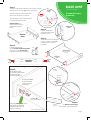
Standard Drawer
Assembly
Step 2.
Clip on metal back
panel to drawer base
& drawer sides.
Step 1.
Secure drawer base to drawer side using 4 x 16mm
drawer runner screws (J) in holes provided.
Seat the edge of drawer base tight
into corner of casing, as shown.
The decorative face of drawer base
to be positioned as shown.
View from
back
Front of drawer
View on side of drawer side
Decorative
face
Drawer
base
1
3
2b
2a
Metal back
panel
Metal back
panel
Drawer base
white decorative
face up
j
j
J
J
j
j
j
j
j
j
Step 4.
Frontal Attachment
Secure drawer side xing clips
using 2 x 21mm screws (Q) in
pilot holes provided as shown.
Step 5.
Draw Adjustment
Screw point 1 as shown
to adjust drawer
frontal right & left.
Drawer
base
Fixing
clip
& (Q)
Fixing
clip
& (Q)
Step 6.
Fit Drawer Cover Caps
over drawer side adjustment.
Screw point 2a as
shown to adjust
drawer frontal
up & down.
Tighten 2b
once in position.
Releasing xing clip. Screw
point 3 whilst applying
downward pressure as
shown to release.
Drawer
Cover Cap
Fixing
clip
Drawer Frontal Adjustment
j
Repeat step 1 so
both drawer sides are
attached to drawer
base.
Step 3.
Screw back panel in position
using 2 x 16mm screws (J)
to drawer base in holes
provided.
Drawer
frontal
Drawer side
xing clip
Q
Q
Drawer
frontal
Drawer
side
Standard
drawer
99mm
67mm
99mm
67mm

BASE UNIT
1000 2/3 Drawer
Assembly Guide
For Internal Use: FI.WR.INS.027_WKIN00111_BASE_1000_2_3Drawer_Rev4.indd
Page 3
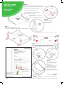
Deep
drawer
231mm
99mm
67mm
231mm
99mm
67mm
Step 1.
Secure drawer base to drawer side using 4 x 16mm
drawer runner screws (J) in holes provided.
Seat the edge of drawerbase tight
into corner ofcasing, as shown.
The decorative face of drawer base
to be positioned as shown.
J
J
J
J
J
J
Drawer
base
Fixing
clip
& (Q)
Fixing
clip
& (Q)
J
J
BASE UNIT
1000 2/3 Drawer
Deep Drawer
Assembly
Step 2.
Clip on metal back
panel to drawer base
& drawer sides.
Gallery
Head
Y & (L)
Gallery
Head
Y & (L)
Step 5.
Draw Adjustment
Screw point 1 as shown to
adjust drawer frontal
right & left.
Step 6.
Fit Gallery Rail into the
top corners of Metal
BackPanel.
Locate front end of the
Gallery Rail into the
opening of the gallery
Head, which is secured to
the frontal as shown
Step 7.
Fit Drawer Cover Caps
over drawer side adjustment.
Drawer
Cover Cap
Drawer Frontal
Adjustment
Screw point 2a
as shown to adjust
drawer frontal up & down.
Tighten 2b
once in position.
Releasing xing clip.
Screw point 3
whilst applying downward pressure as
shown to release.
View on side of drawer side
Front of drawer
Decorative
face
Drawer
base
R
R
Metal back
panel
Drawer base
white decorative
face up
Step 3.
Screw back panel in position using
2 x 16mm screws (J) to drawer base in holes provided.
Step 4.
Secure gallery head and drawer side xing clips
using 2 x 21mm screws (Q) in pilot holes provided
as shown.
Fixing
clip
Repeat step 1 so both drawer
sides are attached to drawer base.
View from
back
Metal
back
panel
Drawer
side
Drawer side
xing clip
Q
Drawer
frontal
Drawer
frontal
2
1
Q

BASE UNIT
1000 2/3 Drawer
Assembly Guide
For Internal Use: FI.WR.INS.027_WKIN00111_BASE_1000_2_3Drawer_Rev4.indd
Page 4
BEFORE YOU START
INSTALLATION
SHOULD BE
PERFORMED BY A
COMPETENT
PERSON ONLY.
THIS PRODUCT COULD
BE DANGEROUS
IF INCORRECTLY
INSTALLED
Panel A
x1 Back Panel
Panel B
x2 End Panel
Panel E
x2 Rail Panel
Panel C
x1 Base Panel
(F) x12
Wooden Dowel
REQUIRED TOOLS
NOT to be used
with CAM DOWEL
& CAM LOCK
(G) x8
Cam Dowel
(Expanding)
(H) x8
Cam Lock
(K) x7
30mm
Screw
(L) x30
15mm
Screw
L Bracket x2 Space Plug x2

BASE UNIT
1000 2/3 Drawer
Assembly Guide
For Internal Use: FI.WR.INS.027_WKIN00111_BASE_1000_2_3Drawer_Rev4.indd
Page 5
2 drawer
3 drawer
4 drawer
600 cabinets used
as reference
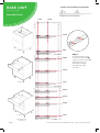
Step 1.
To attach drawer runner
screw into end panels (B)
using 2 x 16mm screws (J)
per drawer rail, into
pilot holes provided,
3rd hole from front,
as shown.
B
B
B
37mm 261mm
646mm
74mm
74mm
503mm
360mm
646mm
360mm
431mm
74mm
from front
from front
from front
from base
from base
from base
Drawer runner bracket screw position
JJ
J
J

BASE UNIT
1000 2/3 Drawer
Carcass Assembly
For Internal Use: FI.WR.INS.027_WKIN00111_BASE_1000_2_3Drawer_Rev4.indd Page 6
Step 2.
Seat dowels (F) into holes in
panels as shown.
Step 3.
Seat cam dowels (G) into holes in
panels as shown.
Step 4.
Attach panels (C) & (E) to
panels (B), using cam dowel (G)
& cam lock (H) (in blue),
and also using dowels (F) (in
orange) in positions as shown.
Step 5.
Join panels (C) & (E) to (B).
Insert cam lock (H). Do NOT
tighten until Step 7.
NB. All Cam Locks (H) are to be positioned facing the
outside of the unit carcass, for ease of tightening.
Do not use power tools with
cam dowel (G) or cam lock (H)
Dowel (F)
& Cam Dowel (G)
location detail
B
B
E
E
C
B
B
C
C
View from underside
H
G
G
View from underside
H
F
F
G
F
F
F
F
F
F
G
G
G
G
F
F
F
F
BB
G
G
G
Seat (G)
cam dowel
into hole as
shown.

BASE UNIT
1000 2/3 Drawer
Carcass Assembly
For Internal Use: FI.WR.INS.027_WKIN00111_BASE_1000_2_3Drawer_Rev4.inddPage 7
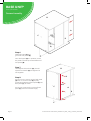
Step 6.
Slide back panel (A) into
groove of end panels (B).
Once back panel (A) is in position, ensure
the panel is ush & square with bottom of
end panels (B).
Step 7.
Hand tighten all cam locks (H), this will
expand cam dowels (G) and tighten the
unit together.
Step 8.
Ensure carcass is square. Secure back panel
(A) with 4 x 30mm screws (K) equally
spaced at the bottom of back panel (A) into
base panel (C), as shown.
Ensure you screw into the centre of base
panel (C) (9mm from bottom edge).
B
C
A
B
E
C
K
A
E
B
9mm

BASE UNIT
1000 2/3 Drawer
Assembly Guide
For Internal Use: FI.WR.INS.027_WKIN00111_BASE_1000_2_3Drawer_Rev4.indd
Page 8
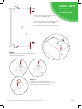
Leg position diagram
Step 11.
Push leg rmly down into leg base.
Adjust legs to 155mm before turning carcass
upright. Once in situ level accordingly.
Step 10.
Lightly hit centre peg of leg base with hammer
until ush with the leg base.
B
Front
Front
Ensure legs are rotated as shown so that part
of it is supporting the end panels (B).
Front legs should have at edge to the front.
Step 9.
Secure each of the legs into place with
2 x 15mmscrews (L) per leg
B
C
Front
L
L
C
B
C C
B
B
C
B

BASE UNIT
1000 2/3 Drawer
Assembly Guide
For Internal Use: FI.WR.INS.027_WKIN00111_BASE_1000_2_3Drawer_Rev4.indd
Page 9
Secure unit to wall using space plug.
Drill pilot hole through the back brace
into the wall and insert
wall plug. Then unwind space plug
until it contacts both surfaces.
Finally, tighten the screw.
Screws for attaching to walls are
not provided as these vary
depending on your wall material and
construction. Ensure appropriate
xings for wall construction are used.
Securing to Adjacent Units
Screw into any side units using
the 30mm screws (K) provided to
secure to unit. Screw just to the rear,
at the top and bottom of both sides
of the unit, place a cover cap
on the head to conceal it.
L Brackets
Use 2 x 15mm screws (L) to secure each
of the L brackets to the cabinets at either side.
Then screw up through into the worktop as shown.
Screws for attaching to worktop are
not supplied as these vary depending
on worktop material and thickness. Ensure
appropriate xings for attaching worktop are
used. L brackets should only be tted for securing
wood and laminate worktops, please refer to the
specialist worktop supplier if these are required
for solid surface worktops.
Worktop
Screw up through the front rail into
your worktop to secure it in place.
Screws for attaching to worktop are not
supplied as these vary depending on worktop
material and thickness. Ensure appropriate
xings for attaching worktop are used.
Please refer to the specialist worktop
supplier if these are required for solid
surface worktops.
L
L
K

BASE UNIT
1000 2/3 Drawer
Carcass Assembly
Page 10

-
 1
1
-
 2
2
-
 3
3
-
 4
4
-
 5
5
-
 6
6
-
 7
7
-
 8
8
-
 9
9
-
 10
10
-
 11
11
-
 12
12


Wren Kitchens 1000 2 Drawer Assembly Guide
- Type
- Assembly Guide
- This manual is also suitable for
Ask a question and I''ll find the answer in the document
Finding information in a document is now easier with AI
Related papers
-
Wren 800 3 Drawer Assembly Manual
-
Wren Kitchens Base Unit 600 2/3 Drawer Assembly Guide Assembly Manual
-
-
-
-
-
Wren 600mm Adjustable Wall Unit Assembly Manual
-
-
-
Other documents
-
Kogan SLPKITBENWB User guide
-
Home Decorators Collection EN1201-CTW Operating instructions
-
-
-
 Walker Edison Furniture Company HD60CGS1CL Installation guide
-
-
Unbranded 2048500410 Operating instructions
-
-
-
