Digital Watchdog VMAX IP Plus DW-VP9P Installation guide

Type
Installation guide

This manual is also suitable for

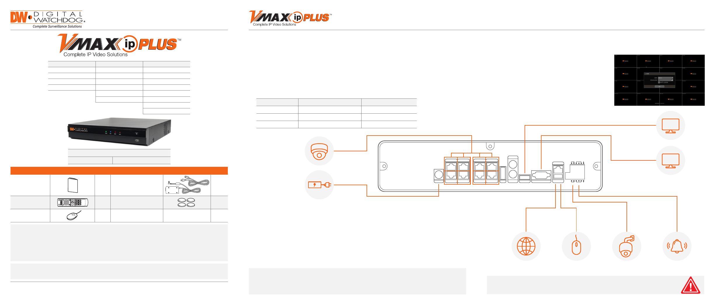
Model Total PoE Power Budget Max Power per Port
DW-VP9-4P 90.24Watt 15.4Watt
DW-VP12-8P 158.4Watt 15.4Watt
DW-VP16-16P 200Watt 15.4Watt
ADAPTER
IP CAMERA
VGA MONITOR
NETWORK CABLE USB MOUSE PTZ CAMERA ALARM / SENSOR
HD MONITOR
DC 48V PoE2
PoE1
PoE4
PoE3
PoE6
PoE5
PoE8
PoE7
AUDIO OUT
TV OUT
eS ATA USB
LAN
PAL
RS485 SENSOR IN
RS485 SENSOR IN
ALARM OUT+
ALARM OUT-
NTSC
TV-OUT VGA
HD OUT VGA OUT
VGA
HD
Back Panel Ports may differ according to model
Default Login Information
Username: admin Password: no password
Quick Start Guide
WHAT’S IN THE BOX
QSG Manual 1 Set
48V D/C & Power Cable
(*DW-VP16xT16P models
come with Power cable only)
1 Set
IR Remote Control
(Optional)
1 Set Rubber Mounts – 4pcs 1 Set
USB Mouse 1 Set
NOTE: Download All Your Support Materials and Tools in One Place
1. Go to: http://www.digital-watchdog.com/support-download/
2. Search your product by entering the part number in the ‘Search by Product search bar. Results for applicable
part numbers will populate automatically based on the part number you enter.
3. Click ‘Search. All supported materials, including manuals, Quick Start Guides (QSG), software and rmware will
appear in the results.
Tel: +1 (866) 446-3595 / (813) 888-9555
Technical Support Hours: 9:00AM – 8:00PM EST, Monday thru Friday
digital-watchdog.com
Attention: This document is intended to serve as a quick reference for initial set-up. It is recommended that
the user read the entire instruction manual for complete and proper installation and usage.
9ch w/4 PoE 12ch w/8 PoE 16ch w/16 PoE
DW-VP9P DW-VP12P DW-VP16P
DW-VP92T4P DW-VP123T8P DW-VP163T16P
DW-VP94T4P DW-VP124T8P DW-VP164T16P
DW-VP96T4P DW-VP126T8P DW-VP166T16P
DW-VP128T8P DW-VP168T16P
DW-VP1212T8P DW-VP1612T16P
DW-VP1618T16P
DW-VP1624T16P
Quick Start Guide
1. Mount and install all necessary IP cameras and external devices. Refer to their individual manuals for
additional information.
2. Place the NVR in its nal position. See installation tips below.
3. Connect all necessary cables to the NVR.
4. Once all additional devices have been properly connected to the NVR, connect the NVR to an
appropriate power supply. The NVR will boot up automatically.
1. When the NVR boots up, it will be in protective mode.
This means you will not be able to access the NVR’s
setup menu until you login using the proper username
and password.
2. To unlock the NVR, right-click anywhere on the screen.
The login screen will appear. (Default Username /
Password: admin / no password)
3. When the NVR boots up for the rst time, you will be
guided through the Startup Wizard.
1. Make sure the cameras and the monitors are properly connected to the NVR.
2. The NVR should be placed in a dust and moisture free environment. It must never be directly exposed
to sunlight. Server room temperature is highly recommended to reduce the chance of overheating,
which may cause the NVR to become unstable.
3. During the boot up process, the NVR should not be interrupted by pressing any buttons on the mouse.
Do not unplug the power adapter or turn the NVR off during the boot up process.
4. A UPS (Uninterrupted Power Supply) is highly recommended to prevent damage to the NVR during
a power outage.
STEP 1 – CONNECTING THE NVR STEP 2 – POWERING UP THE NVR
SAFETY TIPS
NOTE:
1. HD Monitor output and VGA output cannot be used at the same time for dual monitoring.
2. When using the TV output, the NVR’s menu will not be accessible.
3. To connect additional IP cameras to the NVR, connect a PoE switch to the NVR’s network port.
To prevent the NVR from overheating, do not operate it in an area that exceeds the maximum recommended
ambient temperature of 104°F (40°C). To prevent airow restriction, allow at least 3 inches (7.6 cm) of clearance
around the ventilation openings.
1. NAVIGATION – use the included USB mouse to navigate around the NVR’s monitoring and Setup pages.
a. To access the MENU BAR – move the mouse’s cursor to
the bottom of the display area to show the menu bar. You
can also display it constantly by pressing the pin icon on
the right side.
b. To access the QUICK MENU OPTIONS – Right-click
anywhere on the screen. This will take you to the quick
menu options, which include:
Display Mode Options
Camera Control features such as Digital Zoom, Virtual PTZ and Camera Image
Adjustment and Setup
Bookmark video
Instant Playback and Search
Recording and PoE status and analysis such as network and system monitoring
Access to the Main Menu
2. HELP – For your convenience, the HELP button located at the bottom right of setup
screens includes basic information and explanation of the features and settings in that
page, for on-the-go information.
Quick Start Guide
Rev Date: 03/20
Copyright © Digital Watchdog. All rights reserved.
Specications and pricing are subject to change without notice.
4. Set the NVR’s network settings to match your network’s requirements. It is recommended to set the
network type to DHCP and let the NVR auto-detect the network’s settings by selecting the IP detect
button. Then, change the type to Static. Please contact your Network Administrator for additional
information. Press Apply to Save and Next to move to the next step.
1. Follow the startup wizard’s instructions to setup the NVR’s basic settings, including language, date/
time, network and congure your cameras. At any time you can skip steps, go back, or exit the wizard
and setup the NVR manually.
2. Language – Select the appropriate language from the drop-down menu options. Press Apply to Save
and Next to move to the next step.
3. Set the NVR’s date and time, including time zone, Daylight Savings and NTP Time Sync. If needed, set
the NVR to sync its time automatically with an external NTP server. Select the server from the TIME
SYNC MODE/CYCLE drop-down options and the sync interval. Press Apply to Save and Next to move
to the next step.
DDNS Setup
The DDNS address provides your NVR a URL address, easier to remember than an IP address.
This is a free feature supported by Digital Watchdog for its customers.
1. Go to the Network setup menu, and select the ‘DDNS’ tab.
2. Check USE DDNS to enable. (Make sure both the NVR’s web port and TCP/IP port are properly setup
in your router. If you need assistance, please contact your internet service provider).
3. Select DYNLINK.NET (default).
4. Enter a name for your NVR and click the CHECK button. If the name is available, the system will
display the following message: “THIS NVR NAME CAN BE USED”. Click SAVE to save all changes.
5. To use your DDNS, open an Internet Explorer page and enter the DDNS in the address bar:
NVRname.dynlink.net:port-number. (Example: http://vmaxipplus.dynlink.net:80)
5. The VMAX IP Plus’ Camera Conguration screen allows you to detect all the cameras in your network
and automatically add them to the NVR. Select one of the following options:
a. AUTO MANAGEMENT – The system will automatically scan the network and add the rst cameras
it detects to the NVR. Cameras connected directly to the NVR’s PoE Switch will be assigned to
channels automatically.
b. DRAG & DROP CONFIGURATION – The NVR will scan the network for all supported cameras and
display them in a table. Select which cameras to add by click and hold the camera’s name, and
dragging it to the display area to its corresponding channel.
STEP 3 – STARTUP WIZARD STEP 5 – REMOTE MONITORING
STEP 4 – MONITOR YOUR SYSTEM
  • Page 1 1
  • Page 2 2

Digital Watchdog VMAX IP Plus DW-VP9P Installation guide

Type
Installation guide
This manual is also suitable for

Ask a question and I''ll find the answer in the document

Finding information in a document is now easier with AI