Page is loading ...

PART No. 9381798094
AIR CONDITIONER
INDOOR UNIT (Cassette Type)
INSTALLATION MANUAL
For authorized service personnel only.
AUTG30KR
A
AUTG36KR
A
AUTG45KR
A
AUTG54KR
A
9381798094_IM_EN.indd 1 25/08/2020 11:36:57

En-1
1. SAFETY PRECAUTIONS
•Be sure to read this manual thoroughly before installation.
•The warnings and precautions indicated in this Manual contain important information
pertaining to your safety. Be sure to observe them.
•Hand this Manual, together with the operation manual, to the customer. Request the
customer to keep them on hand for future use, such as for relocating or repairing the unit.
WARNING
Indicates a potentially or imminently hazardous situation which,
if not avoided, could result in death or serious injury.
Installation of this product must be done by experienced service technicians or profes-
sional installers only in accordance with this manual. Installation by nonprofessional or
improper installation of the product may cause serious accidents such as injury, water
leakage,electricshock,orre.Iftheproductisinstalledindisregardoftheinstructions
in this manual, it will void the manufacturer’s warranty.
Do not turn on the power until all work has been completed. Turning on the power be-
foretheworkiscompletedcancauseseriousaccidentssuchaselectricshockorre.
If refrigerant leaks when you are working, ventilate the area. If the leaking refrigerant
isexposedtoadirectameitmayproduceatoxicgas.
Donotusethisequipmentwithairoranyotherunspeciedrefrigerantintherefriger-
ant lines. Excess pressure can cause a rupture.
Installation must be performed in accordance with regulations, codes, or standards for
electrical wiring and equipment in each country, region, or the installation place.
Do not use means to accelerate the defrosting process or to clean, other than those
recommended by the manufacturer.
The appliance shall be stored in a room without continuously operating ignition sources
(forexample:openames,anoperatinggasapplianceoranoperatingelectricheater).
Do not pierce or burn.
Be aware that refrigerants may not contain an odour.
This appliance is not intended for use by persons (including children) with reduced
physical, sensory or mental capabilities, or lack of experience and knowledge, unless
they have been given supervision or instruction concerning use of the appliance by a
person responsible for their safety. Children should be supervised to ensure that they
do not play with the appliance.
CAUTION
Indicates a potentially hazardous situation that may result in
minor or moderate injury or damage to property.
Read carefully all safety information written in this manual before you install or use the
air conditioner.
Install the product by following local codes and regulations in force at the place of instal-
lation, and the instructions provided by the manufacturer.
This product is part of a set constituting an air conditioner. The product must not be
installed alone or be installed with non-authorized device by the manufacturer.
Always use a separate power supply line protected by a circuit breaker operating on all
wires with a distance between contact of 3 mm for this product.
To protect the persons, earth (ground) the product correctly, and use the power cable
combined with an Earth Leakage Circuit Breaker (ELCB).
This product is not explosion proof, and therefore should not be installed in explosive
atmosphere.
Donottouchthensoftheheatexchanger.Touchingtheheatexchangernscould
resultindamagetothensorpersonalinjurysuchasskinrupture.
To avoid getting an electric shock, never touch the electrical components soon after the
power supply has been turned off. After turning off the power, always wait 5 minutes or
more before you touch the electrical components.
This product contains no user-serviceable parts. Always consult experienced service
technicians for repairing.
When moving or relocating the air conditioner, consult experienced service technicians
for disconnection and reinstallation of the product.
Do not place any other electrical products or household belongings under the product.
Condensation dripping from the product might get them wet, and may cause damage or
malfunction to the property.
Precautions for using R32 refrigerant
The basic installation work procedures are the same as conventional refrigerant
(R410A, R22) models.
However, pay careful attention to the following points:
Since the working pressure is 1.6 times higher than that of refrigerant R22 models,
some of the piping and installation and service tools are special. (See “2.1. Special
tools for R32 (R410A)”.)
Especially, when replacing a refrigerant R22 model with a new refrigerant R32 model,
always replace the conventional piping and flare nuts with the R32 and R410A piping and
arenutsontheoutdoorunitside.
ForR32andR410A,thesamearenutontheoutdoorunitsideandpipecanbeused.
Models that use refrigerant R32 and R410A have a different charging port thread diam-
eter to prevent erroneous charging with refrigerant R22 and for safety. Therefore, check
beforehand. [The charging port thread diameter for R32 and R410A is 1/2-20 UNF]
Be more careful than R22 so that foreign matter (oil, water, etc.) does not enter the
piping. Also, when storing the piping ,securely seal the opening by pinching, taping, etc.
(Handling of R32 is similar to R410A.)
This manual includes requirements of clauses according to Table DD.1 (Installation,
Maintenance and repair, Decommissioning)
WARNING
Auxiliary devices which may be a potential ignition source shall not be installed in the
duct work.
Examples of such potential ignition sources are hot surfaces with a temperature ex-
ceeding 700°C and electric switching devices.
The appliance shall not be installed in an unventilated space, if that space is smaller
than minimum installation area.
Total refrigerant amount
[kg]
Minimum installation area [m
2
]
Installation height
A: 1.8m ≤ h0 < 2.2m B: 2.2m ≤ h0
≤1.842 - -
1.843 4.47 3.66
2.000 4.85 3.97
2.200 5.33 4.36
2.400 5.81 4.76
2.600 6.45 5.15
2.800 7.48 5.55
3.000 8.59 5.95
3.200 9.77 6.54
3.400 11.03 7.38
3.600 12.36 8.28
3.800 13.77 9.22
4.000 15.26 10.22
4.200 16.82 11.26
4.400 18.46 12.36
4.600 20.18 13.51
4.800 21.97 14.71
5.000 23.84 15.96
1. SAFETY PRECAUTIONS ……………………………………………………………… 1
2. ABOUT THIS PRODUCT ………………………………………………………………… 4
2.1. Special tools for R32 (R410A) …………………………………………………… 4
2.2. Accessories ………………………………………………………………………… 4
2.3. Optional parts ……………………………………………………………………… 4
3. GENERAL SPECIFICATION …………………………………………………………… 4
3.1. Selecting the pipe material ………………………………………………………… 4
3.2. Pipe requirement …………………………………………………………………… 5
3.3. Electrical requirement ……………………………………………………………… 5
3.4. Temperature and humidity range ………………………………………………… 5
4. INSTALLATION WORK ………………………………………………………………… 5
4.1. Selecting an installation location ………………………………………………… 5
4.2. Installation dimension ……………………………………………………………… 5
4.3. Installing the unit …………………………………………………………………… 6
4.4. Installing the drain pipe …………………………………………………………… 7
5. PIPE INSTALLATION …………………………………………………………………… 7
5.1. Pipe connection (Brazed connection) …………………………………………… 8
5.2. Installing heat insulation …………………………………………………………… 8
6. ELECTRICAL WIRING …………………………………………………………………… 8
6.1. Wiring method ……………………………………………………………………… 9
7. CASSETTE GRILLE INSTALLATION ………………………………………………… 10
8. REMOTE CONTROLLER SETTING ………………………………………………… 10
9. FUNCTION SETTING ………………………………………………………………… 10
9.1. Turning on the power …………………………………………………………… 10
9.2. Setting method …………………………………………………………………… 10
9.3. RC Sensor setting ……………………………………………………………… 10
9.4. Function Details ………………………………………………………………… 11
10. SPECIAL INSTALLATION METHODS ……………………………………………… 12
10.1. Group control system …………………………………………………………… 12
10.2. Set the R.C. address (DIP switch setting) …………………………………… 12
10.3. Multiple remote control system ………………………………………………… 13
11. OPTION AND OTHER CONNECTABLE DEVICES ………………………………… 13
11.1. Optional parts …………………………………………………………………… 13
11.2. External input and output ……………………………………………………… 13
12. CHECK LIST …………………………………………………………………………… 14
13. TEST RUN ……………………………………………………………………………… 14
14. CUSTOMER GUIDANCE ……………………………………………………………… 14
15. ERROR CODES ……………………………………………………………………… 15
INSTALLATION MANUAL
PART No. 9381798094
Indoor Unit (Cassette Type)
Contents
NOTE: This manual describes how to install the air conditioner described above. Handling
and installation shall only be done by professionals as outlined in this manual.
9381798094_IM_EN.indd 1 25/08/2020 11:36:58

En-2
(IEC 60335-2-40: 2018)
CAUTION
1 General
1-1 Installation
• That the installation of pipe-work shall be kept to a minimum.
• Install the connection pipe to avoid damage, and protect it with covers as needed.
• Thisproductuseslowammabilityrefrigerant.Complywiththeapplicablenational
regulation regarding the gases.
• Thatareconnectionsshallbeaccessibleformaintenancepurposes.
1-2 Unventilated areas
• Wheninstallingthisproducttoanunventilatedarea,payattentiontopreventre
and explosion caused by the stagnated gas in case of refrigerant leakage. (For
products which contain more than 1.842 kg refrigerant.)
• The appliance shall be stored so as to prevent mechanical damage from occurring.
1-3Qualicationofworkers
• Asthisproductusesammablerefrigerant,itsinstallation,repair,maintenance,
removal, and deposition must be performed by dedicated service personnel who
completedtrainingsandobtainedrelevantcerticatesprovidedbythedomestic
trainingfacilitiesormanufacturescertiedforobtainingrelevantnationalcerticate
stipulated by the applicable law.
2 Information on servicing
(Checks to the area)
• Priortobeginningworkonsystemscontainingammablerefrigerants,safety
checks are necessary to ensure that the risk of ignition is minimized.
• For repair to the refrigerating system, 2-1 to 2-5 shall be completed prior to conduct-
ing work on the system.
2-1 Work procedure
• Work shall be undertaken under a controlled procedure so as to minimize the risk of
aammablegasorvaporbeingpresentwhiletheworkisbeingperformed.
2-2 General work area
• All maintenance staff and others working in the local area shall be instructed on the
nature of work being carried out.
• Workinconnedspacesshallbeavoided.
2-3 Checking for presence of refrigerant
• The area shall be checked with an appropriate refrigerant detector prior to and
duringwork,toensurethetechnicianisawareofpotentiallytoxicorammable
atmospheres.
• Ensure that the leak detection equipment being used is suitable for use with all ap-
plicable refrigerants, i.e. non-sparking, adequately sealed or intrinsically safe.
2-4Presenceofreextinguisher
• If any hot work is to be conducted on the refrigerating equipment or any associated
parts,appropriatereextinguishingequipmentshallbeavailabletohand.
• Have a dry powder or CO
2
reextinguisheradjacenttothechargingarea.
2-5 No ignition sources
• No person carrying out work in relation to a refrigerating system which involves
exposing any pipe work shall use any sources of ignition in such a manner that it
mayleadtotheriskofreorexplosion.
• Allpossibleignitionsources,includingcigarettesmoking,shouldbekeptsufciently
far away from the site of installation, repairing, removing and disposal, during which
refrigerant can possibly be released to the surrounding space. Prior to work taking
place, the area around the equipment is to be surveyed to make sure that there are
noammablehazardsorignitionrisks.“NoSmoking”signsshallbedisplayed.
2-6 Ventilated area
• Ensure that the area is in the open or that it is adequately ventilated before breaking
into the system or conducting any hot work.
• A degree of ventilation shall continue during the period that the work is carried out.
• The ventilation should safely disperse any released refrigerant and preferably expel
it externally into the atmosphere.
2-7 Checks to the refrigerating equipment
• Whereelectricalcomponentsarebeingchanged,theyshallbetforthepurpose
andtothecorrectspecication.
• At all times the manufacturer’s maintenance and service guidelines shall be
followed. If in doubt, consult the manufacturer’s technical department for assistance.
• Thefollowingchecksshallbeappliedtoinstallationsusingammablerefrigerants:
- the actual refrigerant charge is in accordance with the room size within which the
refrigerant containing parts are installed;
- the ventilation machinery and outlets are operating adequately and are not
obstructed;
- if an indirect refrigerating circuit is being used, the secondary circuit shall be
checked for the presence of refrigerant;
- marking to the equipment continues to be visible and legible. Markings and signs
that are illegible shall be corrected;
- refrigerating pipe or components are installed in a position where they are unlikely
to be exposed to any substance which may corrode refrigerant containing compo-
nents, unless the components are constructed of materials which are inherently
resistant to being corroded or are suitably protected against being so corroded.
2-8 Checks to electrical devices
• Repair and maintenance to electrical components shall include initial safety checks
and component inspection procedures.
• If a fault exists that could compromise safety, then no electrical supply shall be con-
nected to the circuit until it is satisfactorily dealt with.
• If the fault cannot be corrected immediately but it is necessary to continue opera-
tion, an adequate temporary solution shall be used.
• This shall be reported to the owner of the equipment so all parties are advised.
• Initial safety checks shall include:
- that capacitors are discharged: this shall be done in a safe manner to avoid pos-
sibility of sparking;
- that no live electrical components and wiring are exposed while charging, recov-
ering or purging the system;
- that there is continuity of earth bonding.
3 Repairs to sealed components
• During repairs to sealed components, all electrical supplies shall be disconnected
from the equipment being worked upon prior to any removal of sealed covers, etc.
• If it is absolutely necessary to have an electrical supply to equipment during servic-
ing, then a permanently operating form of leak detection shall be located at the most
critical point to warn of a potentially hazardous situation.
• Particular attention shall be paid to the following to ensure that by working on elec-
trical components, the casing is not altered in such a way that the level of protection
is affected. This shall include damage to cables, excessive number of connections,
terminalsnotmadetooriginalspecication,damagetoseals,incorrectttingof
glands, etc.
• Ensure that the apparatus is mounted securely.
• Ensure that seals or sealing materials have not degraded to the point that they
nolongerservethepurposeofpreventingtheingressofammableatmospheres.
Replacementpartsshallbeinaccordancewiththemanufacturer’sspecications.
4 Repair to intrinsically safe components
• Do not apply any permanent inductive or capacitance loads to the circuit without
ensuring that this will not exceed the permissible voltage and current permitted for
the equipment in use.
• Intrinsically safe components are the only types that can be worked on while live in
thepresenceofaammableatmosphere.Thetestapparatusshallbeatthecorrect
rating.
• Replacecomponentsonlywithpartsspeciedbythemanufacturer.Otherpartsmay
result in the ignition of refrigerant in the atmosphere from a leak.
NOTE: The use of silicon sealant can inhibit the effectiveness of some types of leak
detection equipment.
Intrinsically safe components do not have to be isolated prior to working on
them.
5 Cabling
• Check that cabling will not be subject to wear, corrosion, excessive pressure, vibra-
tion, sharp edges or any other adverse environmental effects.
• The check shall also take into account the effects of aging or continual vibration
from sources such as compressors or fans.
6Detectionofammablerefrigerants
• Under no circumstances shall potential sources of ignition be used in the searching
for or detection of refrigerant leaks.
• Ahalidetorch(oranyotherdetectorusinganakedame)shallnotbeused.
9381798094_IM_EN.indd 2 25/08/2020 11:36:58

En-3
10 Decommissioning
• Before carrying out this procedure, it is essential that the technician is completely
familiar with the equipment and all its detail.
• It is recommended good practice that all refrigerants are recovered safely.
• Prior to the task being carried out, an oil and refrigerant sample shall be taken in
case analysis is required prior to re-use of recovered refrigerant.
• It is essential that electrical power is available before the task is commenced.
a) Become familiar with the equipment and its operation.
b) Isolate system electrically.
c) Before attempting the procedure, ensure that:
• mechanical handling equipment is available, if required, for handling refriger-
ant cylinders;
• all personal protective equipment is available and being used correctly;
• the recovery process is supervised at all times by a competent person;
• recovery equipment and cylinders conform to the appropriate standards.
d) Pump down refrigerant system, if possible.
e) If a vacuum is not possible, make a manifold so that refrigerant can be removed
from various parts of the system.
f) Make sure that cylinder is situated on the scales before recovery takes place.
g) Start the recovery machine and operate in accordance with instructions.
h)Donotoverllcylinders(nomorethan80%volumeliquidcharge).
i) Do not exceed the maximum working pressure of the cylinder, even temporarily.
j)Whenthecylindershavebeenlledcorrectlyandtheprocesscompleted,make
sure that the cylinders and the equipment are removed from site promptly and all
isolation valves on the equipment are closed off.
k) Recovered refrigerant shall not be charged into another refrigerating system un-
less it has been cleaned and checked.
11 Labelling
• Equipment shall be labelled stating that it has been de-commissioned and emptied
of refrigerant.
• The label shall be dated and signed.
• Forappliancescontainingammablerefrigerants,ensurethattherearelabelson
theequipmentstatingtheequipmentcontainsammablerefrigerant.
12 Recovery
• When removing refrigerant from a system, either for servicing or decommissioning,
it is recommended good practice that all refrigerants are removed safely.
• When transferring refrigerant into cylinders, ensure that only appropriate refrigerant
recovery cylinders are employed.
• Ensure that the correct number of cylinders for holding the total system charge is
available.
• All cylinders to be used are designated for the recovered refrigerant and labelled for
that refrigerant (i.e. special cylinders for the recovery of refrigerant).
• Cylinders shall be complete with pressure-relief valve and associated shut-off
valves in good working order.
• Empty recovery cylinders are evacuated and, if possible, cooled before recovery
occurs.
• The recovery equipment shall be in good working order with a set of instructions
concerning the equipment that is at hand and shall be suitable for the recovery of
allappropriaterefrigerantsincluding,whenapplicable,ammablerefrigerants.In
addition, a set of calibrated weighing scales shall be available and in good working
order.
• Hoses shall be complete with leak-free disconnect couplings and in good condition.
• Before using the recovery machine, check that it is in satisfactory working order,
has been properly maintained and that any associated electrical components are
sealed to prevent ignition in the event of a refrigerant release. Consult manufacturer
if in doubt.
• The recovered refrigerant shall be returned to the refrigerant supplier in the correct
recovery cylinder, and the relevant waste transfer note arranged.
• Do not mix refrigerants in recovery units and especially not in cylinders.
• If compressors or compressor oils are to be removed, ensure that they have been
evacuatedtoanacceptableleveltomakecertainthatammablerefrigerantdoes
not remain within the lubricant.
• The evacuation process shall be carried out prior to returning the compressor to the
suppliers.
• Only electric heating to the compressor body shall be employed to accelerate this
process.
• When oil is drained from a system, it shall be carried out safely.
Explanation of symbols displayed on the indoor unit or outdoor unit.
WARNING
This symbol shows that this product uses a low burning
velocity material. If the refrigerant is leaked and exposed
toanexternalignitionsource,thereisariskofre.
CAUTION
This symbol shows that the operation manual should be
read carefully.
CAUTION
This symbol shows that a service personnel should be
handling this equipment with reference to the installation
manual.
CAUTION
This symbol shows that information is available such as
the operation manual or installation manual.
7 Leak detection methods
• The following leak detection methods are deemed acceptable for all refrigerant
systems.
• Electronic leak detectors may be used to detect refrigerant leaks but, in the case
ofammablerefrigerants,thesensitivitymaynotbeadequate,ormayneedre-
calibration.
(Detection equipment shall be calibrated in a refrigerant-free area.)
• Ensure that the detector is not a potential source of ignition and is suitable for the
refrigerant used.
• Leak detection equipment shall be set at a percentage of the LFL of the refrigerant
and shall be calibrated to the refrigerant employed, and the appropriate percentage
ofgas(25%maximum)isconrmed.
• Leakdetectionuidsarealsosuitableforusewithmostrefrigerantsbuttheuseof
detergents containing chlorine shall be avoided as the chlorine may react with the
refrigerant and corrode the copper pipe-work.
NOTE:
Examplesofleakdetectionuidsare
- bubble method,
-uorescentmethodagents.
• Ifaleakissuspected,allnakedamesshallberemoved/extinguished.
• If a leakage of refrigerant is found which requires brazing, all of the refrigerant shall
be recovered from the system, or isolated (by means of shut off valves) in a part of
the system remote from the leak.
8 Removal and evacuation
• When breaking into the refrigerant circuit to make repairs – or for any other purpose
–conventionalproceduresshallbeused.However,forammablerefrigerantsitis
importantthatbestpracticeisfollowedsinceammabilityisaconsideration.The
following procedure shall be adhered to:
- remove refrigerant;
- purge the circuit with inert gas (optional for R32);
- evacuate (optional for R32);
- purge with inert gas (optional for R32);
- open the circuit by cutting or brazing.
• The refrigerant charge shall be recovered into the correct recovery cylinders.
• ForappliancescontainingammablerefrigerantsotherthanR32refrigerants,the
system shall be purged with oxygen-free nitrogen to render the appliance safe for
ammablerefrigerants.
• This process may need to be repeated several times.
• Compressed air or oxygen shall not be used for purging refrigerant systems.
• Forappliancescontainingammablerefrigerants,otherthanR32refrigerants,
refrigerants purging shall be achieved by breaking the vacuum in the system with
oxygen-freenitrogenandcontinuingtolluntiltheworkingpressureisachieved,
thenventingtoatmosphere,andnallypullingdowntoavacuum.
• This process shall be repeated until no refrigerant is within the system.
• Whenthenaloxygen-freenitrogenchargeisused,thesystemshallbevented
down to atmospheric pressure to enable work to take place.
• This operation is absolutely vital if brazing operations on the pipe-work are to take
place.
• Ensure that the outlet for the vacuum pump is not close to any potential ignition
sources and that ventilation is available.
9 Charging procedures
• In addition to conventional charging procedures, the following requirements shall be
followed.
- Ensure that contamination of different refrigerants does not occur when using
charging equipment.
Hoses or lines shall be as short as possible to minimize the amount of refrigerant
contained in them.
- Cylinders shall be kept in an appropriate position according to the instructions.
- Ensure that the refrigerating system is earthed prior to charging the system with
refrigerant.
-Extremecareshallbetakennottooverlltherefrigeratingsystem.
• Prior to recharging the system, it shall be pressure tested with the appropriate
purging gas.
• The system shall be leak tested on completion of charging but prior to commission-
ing.
• A follow up leak test shall be carried out prior to leaving the site.
9381798094_IM_EN.indd 3 25/08/2020 11:36:58

En-4
2. ABOUT THIS PRODUCT
2. 1. Special tools for R32 (R410A)
Tool name Change from R22 to R32 (R410A)
Gauge manifold
Pressure is high and cannot be measured with a R22
gauge. To prevent erroneous mixing of other refrigerants,
the diameter of each port has been changed.
It is recommended to use gauge with seals -0.1 to 5.3 MPa
(-1 to 53 bar) for high pressure.
-0.1 to 3.8 MPa (-1 to 38 bar) for low pressure.
Charge hose
To increase pressure resistance, the hose material and base
size were changed. (R32/R410A)
Vacuum pump
A conventional vacuum pump can be used by installing a
vacuum pump adapter.
(Use of a vacuum pump with a series motor is prohibited.)
Gas leakage detector
Special gas leakage detector for HFC refrigerant R410A or
R32.
Copper pipes
It is necessary to use seamless copper pipes and it is desirable that the amount of residual
oil is less than 40 mg/10 m. Do not use copper pipes having a collapsed, deformed or
discolored portion (especially on the interior surface). Otherwise, the expansion value or
capillary tube may become blocked with contaminants.
As an air conditioner using R32 (R410A) incurs pressure higher than when using R22, it is
necessary to choose adequate materials.
WARNING
•UsespeciedR32orR410Apipingonly.Forindoorunits,useR32arelessjointnut
assyonly.Foroutdoorunits,useR32orR410Aarenutsonly.
Useofpipes,arelessnutsorarenutsotherthanspecied,maycauseproduct
malfunction, burst piping, or injury due to high internal pressure of the refrigerant cycle
causedbyanyinowair.
•Use(rellorreplacewith)speciedrefrigerant(R32)only.Useofunspeciedrefriger-
ant can cause product malfunction, burst, or injury.
•Donotmixanygasorimpuritiesexceptspeciedrefrigerant(R32).Inowofairorap-
plicationofunspeciedmaterialmakestheinternalpressureoftherefrigerantcycletoo
high, and may cause product malfunction, burst of piping, or injury.
2. 2. Accessories
WARNING
For installation purposes, be sure to use the parts supplied by the manufacturer or
other prescribed parts.
The use of non-prescribed parts can cause serious accidents such as the unit falling,
waterleakage,electricshock,orre.
•The following installation parts are furnished. Use them as required.
•Keep the installation manual in a safe place and do not discard any other accessories
until the installation work has been completed.
Name and Shape Q’ty Description
Installation manual
1
(This book)
Template
(Carton top)
1
For installing indoor unit
Washer
8
For installing indoor unit
Coupler heat insulation (Large)
1
For indoor side pipe joint (Gas pipe)
Coupler heat insulation (Small)
1
For indoor side pipe joint
(Liquid pipe)
Insulation
1
For installing drain pipe
Drain hose
1
For installing drain pipe
VP25 (O.D.32, I.D.25)
Hose Band
1
For installing drain hose
Drain hose heat insulation
1
For installing drain pipe
Cable tie (Large)
4
Forconnectionpipexing.
Cable tie (Small)
2
Only one is used for this model.
2. 3. Optional parts
Parts name Model No. Summary
Wired Remote Controller UTY-RVNYN
For air conditioner operation
(3-wire type)
Wired Remote Controller UTY-RNRYZ1
For air conditioner operation
(2-wire type)
IR receiver unit UTY-LBTYC For air conditioner operation
Wide panel UTG-AKXA-W
Wide panel hides the gap
between the ceiling hole and
the Cassette grille.
Panel spacer UTG-BKXA-W
Installation in a space of 56
mm or greater is possible by
using panel spacer when the
height behind the ceiling is low.
Air outlet shutter plate UTR-YDZK
Install the plate at outlet when
carrying out 3-way direction
operation
Insulation kit for High
humidity
UTZ-KXRA
Install when the condition
undertheroofisover80%
in humidity and over 30°C in
temperature.
Fresh air intake kit UTZ-VXRA To take fresh air
External input and output
PCB
UTY-XCSX
For connecting external
devices
External input and output
PCB box
UTZ-GXRA
For installing the External input
and output PCB
External connect kit UTY-XWZXZG For control output port
3. GENERAL SPECIFICATION
3. 1. Selecting the pipe material
CAUTION
Do not use existing pipes.
Use pipes that have clean external and internal sides without any contamination which
may cause trouble during use, such as sulfur, oxide, dust, cutting waste, oil, or water.
It is necessary to use seamless copper pipes.
Material : Phosphor deoxidized seamless copper pipes
It is desirable that the amount of residual oil is less than 40 mg/10 m.
Do not use copper pipes that have a collapsed, deformed, or discolored portion (es-
pecially on the interior surface). Otherwise, the expansion valve or capillary tube may
become blocked with contaminants.
Improper pipe selection will degrade performance. As an air conditioner using R32
(R410A) incurs pressure higher than when using conventional refrigerant, it is neces-
sary to choose adequate materials.
•Thicknesses of copper pipes used with R32 (R410A) are as shown in the table.
•Never use copper pipes thinner than those indicated in the table even if they are available
on the market.
Pipe outside diameter [mm (in.)] Thickness [mm]
6.35 (1/4) 0.8
9.52 (3/8) 0.8
12.70 (1/2) 0.8
15.88 (5/8) 1.0
19.05 (3/4) 1.2
9381798094_IM_EN.indd 4 25/08/2020 11:37:00

En-5
3. 2. Pipe requirement
CAUTION
Refer to the installation manual of the outdoor unit for description of the length of con-
necting pipe or for difference of its elevation.
Diameter [mm (in.)]
Liquid
9.52 (3/8)
Gas
15.88 (5/8)
• Use pipe with water-resistant heat insulation.
CAUTION
Install heat insulation around both the gas and liquid pipes. Failure to do so may
cause water leaks.
Use heat insulation with heat resistance above 120 °C. (Reverse cycle model only)
In addition, if the humidity level at the installation location of the refrigerant piping is
expectedtoexceed70%,installheatinsulationaroundtherefrigerantpiping.
Iftheexpectedhumiditylevelis70-80%,useheatinsulationthatis15mmorthicker
andiftheexpectedhumidityexceeds80%,useheatinsulationthatis20mmor
thicker.Ifheatinsulationisusedthatisnotasthickasspecied,condensationmay
form on the surface of the insulation.
In addition, use heat insulation with heat conductivity of 0.045 W/(m·K) or less (at 20 °C).
3. 3. Electrical requirement
The indoor unit is powered from the outdoor unit. Do not power indoor unit from separate
power source.
WARNING
Standard for electrical wiring and equipment differs in each country or region. Before you
startelectricalworking,conrmrelatedregulations,codes,orstandards.
Cable
Conductor size
(mm
2
)
Type
Remarks
Connection cable 1.5 (MIN.) Type 60245 IEC57
3Cable+Earth (Ground),
1φ240V
Max.CableLength:Limitvoltagedroptolessthan2%.Increasecablegaugeifvoltage
dropis2%ormore.
Cable
Conductor size
(mm
2
)
Type
Remarks
Remote controller
cable
(2-wire type)
0.33 to 1.25
Use shielded cable
(locally purchased)
in accordance with
the regional cable
standard.
Non-polar 2-wired,
twisted pair
Remote controller
cable
(3-wire type)
0.33 Polar 3-wired
3. 4. Temperature and humidity range
Indoor Cooling / Dry mode Heating mode
Thermostat setting range About 18 to 32 °C About 16 to 30 °C
Humidity About80%orless –
4. INSTALLATION WORK
WARNING
Do not turn on the power until all installation work is complete.
Carryingandinstallationoftheunitshouldbeperformedbyasufcientnumberof
peopleandwithsufcientequipmentthatisadequatefortheweightoftheunit.
Performingsuchworkwithaninsufcientnumberofpeopleorwithinadequateequip-
ment could result in dropping of the unit or personal injury.
CAUTION
For installation details, refer to the technical data.
4. 1. Selecting an installation location
Decide the mounting position together with the customer as follows.
WARNING
Select installation locations that can properly support the weight of the indoor unit
and which will not amplify sound or vibration. If the installation location is not strong
enough, the indoor unit may fall and cause injuries.
Install the units securely so that they do not topple or fall.
CAUTION
Do not install the indoor unit in the following areas:
• Area with high salt content, such as at the seaside.
It will deteriorate metal parts, causing the parts to fall or the unit to leak water.
• Arealledwithmineraloilorcontainingalargeamountofsplashedoilorsteam,
such as a kitchen.
It will deteriorate plastic parts, causing the parts to fall or the unit to leak water.
• Area that generates substances that adversely affect the equipment, such as sulfuric
gas, chlorine gas, acid, or alkali. It will cause the copper pipes and brazed joints to
corrode, which can cause refrigerant leakage.
• Areathatcancausecombustiblegastoleak,containssuspendedcarbonbersor
ammabledust,orvolatileinammablessuchaspaintthinnerorgasoline.Ifgas
leaksandsettlesaroundtheunit,itcancauseare.
• Area where animals may urinate on the unit or ammonia may be generated.
Do not use the unit for special purposes, such as storing food, raising animals, growing
plants, or preserving precision devices or art objects. It can degrade the quality of the
preserved or stored objects.
Do not install where there is the danger of combustible gas leakage.
Donotinstalltheunitnearasourceofheat,steam,orammablegas.
Install the unit where drainage does not cause any trouble.
Install the indoor unit, outdoor unit, power supply cable, transmission cable, and remote
control cable at least 1 m away from a television or radio receivers. The purpose of this
is to prevent TV reception interference or radio noise.
(Even if they are installed more than 1 m apart, you could still receive noise under
some signal conditions.)
Install the unit where ambient temperature does not reach 60°C or more.
Take a measure such as ventilation for an environment in which heat is retained.
If children under 10 years old may approach the unit, take preventive measures so that
they cannot reach the unit.
Installtheindoorunitontheplacewheretheheightfromtheoorismorethan1.8m.
Use the “Insulation kit for high humidity” (option), when the condition under the roof
isover80%inhumidityandover30°Cintemperature.Otherwise,thereisariskof
condensation on the ceiling.
(1) Locate where the air can be distributed evenly throughout the room by the unit.
(2) The inlet and outlet ports should not be obstructed; the air should be able to blow all
over the room.
(3) Leave the space required to service the air conditioner.
(4) Install the unit where connection to the outdoor unit is easy.
(5) Install the unit where the connection pipe can be easily installed.
(6) Install the unit where the drain pipe can be easily installed.
(7) Installtheunitwherenoiseandvibrationsarenotamplied.
(8) Take servicing, etc., into consideration and leave the spaces. Also install the unit where
theltercanberemoved.
(9) Do not install the unit where it will be exposed to direct sunlight.
Correctinitialinstallationlocationisimportantbecauseitisdifculttomoveunitafteritis
installed.
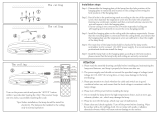
4. 2. Installation dimension
•Theceilingrearheightasshowninthegure.
Strong and durable ceiling
3 or more
Floor
Obstruction
Unit: m
1.5 or
more
1.8 or more
1 or more
•This product can be installed at a height of up to 4.2 m. However, if the heights of the
ceiling is higher than 3.2 m or lower than 2.7 m, it is necessary to set the position from
remote controller. (See 9. FUNCTION SETTING)
Discharge direction setting
Unit : mm
•The discharge direction can be selected as shown below.
100 or more*
(4 directions) (3 directions)
*Pleaseensuresuf-
cient service access
during installation.
• For a 3-way outlet, make sure to perform the function setting on the remote control.
Also, make sure to use the optional shutter plate to block the outlet.
9381798094_IM_EN.indd 5 25/08/2020 11:37:00

En-6
• The ceiling height cannot be set in the 3-way outlet mode. Therefore, do not change the
setting in the setting the ceiling height. (See 9. FUNCTION SETTING)
• When the outlet is shut, be sure to install the optional Air outlet shutter plate kit. For the
details of installation, please refer to installation manual of the kit.
Human sensor
CAUTION
•Do not hit or push the human sensor. This may lead to damage or malfunction.
•Do not touch the human sensor. Any scratches or dirt may lead to incorrect detection.
•Donotplacelargeobjectsnearthe
human
sensor. Also keep heating units outside the
sensor’s detection area.
Example of sensitivity range:
When the installation height gets higher, the temperature sensitivity decreases.
Drain
pipe
Refrigerant
pipe
Top view
Human
sensor
0.8m
8.8m
3.2m
Equal sensitivity range of
temperature
Ceiling height: 3.2 m
Detectingposition:0.8mfromoorsurface
4. 3. Installing the unit
WARNING
Carryingandinstallationoftheunitshouldbeperformedbyasufcientnumberof
peopleandwithsufcientequipmentthatisadequatefortheweightoftheunit.Per-
formingsuchworkwithaninsufcientnumberofpeopleorwithinadequateequipment
could result in dropping of the unit or personal injury.
If the job is done with the panel frame only, there is a risk that the unit will come loose.
Please take care.
When fastening the hangers, make the bolt positions uniform.
4.3.1. Position the ceiling hole and hanging bolts
(1) Positions of the ceiling opening, hanging bolt pitch, piping and ducts.
• Ceiling opening and hanging bolt pitch.
Unit: mm
950(Panel frame)
860 - 910(Ceiling opening)
768(Hanging bolt pitch)
840(Body frame)
860 - 910(Ceiling opening)
950(Panel frame)
840(Body frame)
796(Hanging bolt pitch)
20 - 45
20 - 45
50
200
20 - 45
20 - 45
130
130
130
130
200 - 205
39
10
288
298
50 - 100
• Refrigerant piping and drain piping positions.
Unit: mm
Liquid pipe
293
45
342
200
140
180
130
Gas pipe
Drain pipe
(Connect the
attached drain
hose)
10
• Distribution ducts and fresh air inlet positions.
Unit: mm
Distribution duct connecting port
Detailed diagram of distribution duct
connecting port (4 sides)
bolt pitch
Cut out
Cut out
95
232
114
100
100
83
83
352
90
163
163
Fresh air inlet position
10 ×
3.2 hole
4 ×
3.2 hole
Distribution duct
connecting port
Distribution duct connecting port
Distribution duct connecting port
Fresh air inlet
position
Drain pipe
Refrigerant pipe
Note:
Conduct proper insulation when connecting the distribution ducts and fresh air inlet.
Insulation
Fresh air inlet position
NOTE:
Whenintroducingfreshairintotheindoorunit,pleaseremovetheinsulationafxedtothe
drain pan.
(2) Setting the positions of hanging bolt and ceiling opening.
•Use an installation template (packaging top surface) to set the positions of the hanging
bolt and ceiling opening and drill holes.
(3) Hanging structure.
•Select a strong structure for the hanging location.
•If necessary, reinforce the hanging bolt with quake proof columnar support material to
prevent shaking.
•Use hanging bolts of M8-M10.
4.3.2. Body installation
(1) Install the attached washer and nut (prepared on site) onto the hanging bolt.
(2) Hook the body onto the hanging bolt.
(3) Adjust the dimensions of the ceiling surface from the body. After installing the Cassette
grille,youcanmakeneadjustmentoftheheightofthebody.Fordetails,refertothe
installation manual of the Cassette grille.
WARNING
Performnaltighteningbytighteningthedoublenutrmly.
Be sure to install the body horizontally and adjust the height below the body and the
ceiling surface properly.
10~15
Hanging bolt (locally purchased)
Nut A (locally purchased)
Washer (Accessories)
After installing the body,
tighten the nuts.
Unit: mm
Washer (Accessories)
Nut B (Double Nut)
(locally purchased)
9381798094_IM_EN.indd 6 25/08/2020 11:37:02

En-7
4.3.3. Leveling
Usingalevel,orvinylhoselledwithwater,neadjustsothatthebodyislevel.
Inclinedinstallationsoasthedrainpipesideishighermaycauseamalfunctionoftheoat
switch, and may cause water leakage.
Vinyl hoses
Drain pipe
4. 4. Installing the drain pipe
WARNING
Do not insert the drain piping into the sewer where sulfurous gas occurs. (Heat ex-
change erosion may occur.)
Insulate the parts properly so that water will not drip from the connection parts.
Check for proper drainage after the construction by using the visible portion of transpar-
entdrainportandthedrainpipingnaloutletonthebody.
CAUTION
Do not apply adhesive agent on the drain port of the body. (Use the attached drain
hose and connect the drain piping.)
Install the drain pipe:
•Install the drain pipe with downward gradient (1/50 to 1/100) and so there are no rises or
traps in the pipe.
•Use general hard polyvinyl chloride pipe (VP25) [outside diameter 32 mm] and connect it
with adhesive (polyvinyl chloride) so that there is no leakage.
•When the pipe is long, install supporters.
•Do not perform air bleeding.
•Always heat insulate the indoor side of the drain pipe.
•Ifitisimpossibletohavesufcientgradientofpipe,performdrainlift-up.
Pipe size
Drain pipe VP25 (O.D. 32 mm)
Hangingttings
1.5 to 2 m
VP25 (O.D. 32 mm)
Downward gradient 1/100 to 1/50
Rise
PROHIBITED:
Trap
Air bleeding
When lifting up drain:
• Height of inclined pipe should be less than 850 mm from the ceiling. A rise dimension over
this range will cause leakage.
• Lift up the pipe vertically at the position of 300 mm or less from the unit.
300 mm or less
VP25 (O.D. 32 mm)
local arrangement
850 mm or less
Horizontal or
upward gradient
Downward gradient
1/100 to 1/50
VP30 (O.D. 38 mm) or more Downward
gradient 1/100 to 1/50
850 mm or less
Working procedure
(1) Install the attached drain hose to the drain port of the body. Attach hose band on top of
the drain hose.
(2) Use vinyl adhesive agent to glue the drain piping (PVC pipe VP25) which is prepared
on site or elbow socket. (Apply color adhesive agent evenly until the gauge line and
seal.)
(3) Check the drainage.
(4) Install the heat insulation.
(5) Use the attached heat insulation to insulate the drain port and band parts of the body.
Install the knob faces
upward
Attached drain hose
heat insulation
Attached heat insulation
Attached
hose band
Locally arranged
vinyl pipe
Attached drain hose
(a) Top view
(c) Top view
(b) Side view
VP25
Applying area of
adhesive
35
4 or less
Gauge line
Hose band
5-10
20
Make sure there
are no gaps
Wind the attached heat insulation
around the hose band
(d) Hose opening view
Make sure the alignment is
on top
Unit: mm
5. PIPE INSTALLATION
WARNING
Duringinstallation,makesurethattherefrigerantpipeisattachedrmlybeforeyou
run the compressor.
Do not operate the compressor under the condition of refrigerant piping not attached
properly with 2-way or 3-way valve open. This may cause abnormal pressure in the
refrigeration cycle that leads to breakage and even injury.
During the pump-down operation, make sure that the compressor is turned off before
you remove the refrigerant piping.
Do not remove the connection pipe while the compressor is in operation with 2-way or
3-way valve open. This may cause abnormal pressure in the refrigeration cycle that
leads to breakage and even injury.
When installing and relocating the air conditioner, do not mix gases other than the
speciedrefrigerant(R32orR410A)toentertherefrigerantcycle.
If air or other gas enters the refrigerant cycle, the pressure inside the cycle will rise to
an abnormally high value and cause breakage, injury, etc.
If refrigerant leaks while work is being carried out, ventilate the area. If the refrigerant
comesincontactwithaame,itproducesatoxicgas.
CAUTION
Be more careful so that foreign matter (oil, water, etc.) does not enter the piping than
with refrigerant R32 or R410A models. Also, when storing the piping, securely seal the
openings by pinching, taping, etc.
While brazing the pipes, be sure to purge with dry nitrogen gas.
9381798094_IM_EN.indd 7 25/08/2020 11:37:03

En-8
5. 1. Pipe connection (Brazed connection)
5.1.1. Brazing
CAUTION
If air or another type of refrigerant enters the refrigeration cycle, the internal pressure in
the refrigeration cycle will become abnormally high and prevent the unit from exerting its
full performance.
Apply nitrogen gas while brazing the pipes.
Nitrogen gas pressure: 0.02 MPa
(=pressurefeltsufcientlyonthebackofyourhand)
Pressure regulating valve
Cap
Nitrogen gas
Brazing area
Ifapipeisbrazedwithoutapplyingnitrogengas,itwillcreateanoxidationlm.
This can degrade performance of damage the parts in the unit (such as the compressor
or valves).
Donotuseuxtobrazepipes.Iftheuxisthechlorinetype,itwillcausethepipes
tocorrode.Inaddition,iftheuxcontainsuoride,itwillaffecttherefrigerantpiping
system due to deterioration of refrigerant oil.
Forbrazingmaterial,usephosphorcopperthatdoesnotrequireux.
Ventilatetheareaappropriatelywhenbrazing,topreventrespread.
Whenbrazing,makesurethatthereisnohazardousorinammableobjectsinthe
surroundingareatoavoidriskofre.
5.1.2. Bending pipes
•If pipes are shaped by hand, be careful not to collapse them.
•Do not bend the pipes in an angle more than 90°.
•Whenpipesarerepeatedlybendorstretched,thematerialwillharden,makingitdifcult
to bend or stretch them any more.
•Do not bend or stretch the pipes more than three times.
CAUTION
To prevent breaking of the pipe, avoid sharp bends. Bend the pipe with a radius of
curvature of 150 mm or over.
If the pipe is bent repeatedly at the same place, it will break.
5.1.3. Connecting pipes
• Thegasandliquidpipesconnectionsmustbebrazed.
• Besuretobrazethembeforeperforminganywiringworkorinstallingthedrainpipe.
Liquid pipe
Cabinet
Gas pipe
Pinch pipe
Pipe cover
Pipe heat insulation
WARNING
• Besuretousewetcloth,etc.,toprotectthepipeheatinsulationasshownbelow.
Becausethesepartsareextremelyammable,theycancauseareiftheyarenot
properly protected.
• Donotexposetheunit(cabinet,pipecover,etc.)andtheinletgrilletotheame.
Theexposureofthesepartstotheamewilladverselyaffecttheirappearanceand
functionsorcauseare.
Do not expose the pipe cover and
Cabinettotheame.
Protect these areas with wet cloth, etc.
Pinch pipe
Pinch pipe
Completely
cover the pipe
heat insulation
with wet cloth,
etc., to prevent
them from burn-
ing.
CAUTION
• Meltthebrazingltermetalonconnectingpartusingaburnerandremovethepinch
pipe.
• Removethepinchpipeonlyafterprotectingitfromame.
• Removethepinchpipeimmediatelybeforetheconnection.
5. 2. Installing heat insulation
Install the heat insulation material after performing a refrigerant leak check (see the
installation manual for the outdoor unit for details).
After checking for the gas leaks, insulate by wrapping insulation around the 2 parts (gas
and liquid) of the indoor unit coupling, using the Coupler heat insulation.
After installing the Coupler heat insulation, wrap both ends with vinyl tape so that there is no gap.
No gap
Be sure to overlap
the insulation
Coupler heat
insulation
Body
Cable tie (Large)
(Accessories)
Coupler heat
insulation
(Accessories)
No gap
CAUTION
There should be no gaps between the insulation and the product.
CAUTION
After connecting the piping, check all the joints for gas leakage with gas leak detector.
Once the pressure checking has been completed using nitrogen, please refer to the
outdoor installation manual to complete the evacuation process.
Install heat insulation around both the large (gas) and small (liquid) pipes. Failure to
do so may cause water leaks.
6. ELECTRICAL WIRING
WARNING
ElectricalworkmustbeperformedinaccordancewiththisManualbyapersoncertied
under the national or regional regulations. Be sure to use a dedicated circuit for the unit.
Aninsufcientpowersupplycircuitorimproperlyperformedelectricalworkcancause
seriousaccidentssuchaselectricshockorre.
Before starting work, check that power is not being supplied to the indoor unit and outdoor unit.
Usetheincludedconnectioncablesandpowercablesoronesspeciedbythemanu-
facturer.Improperconnections,insufcientinsulation,orexceedingtheallowable
currentcancauseelectricshockorre.
For wiring, use the prescribed type of cables, connect them securely, making sure that
there are no external forces of the cables applied to the terminal connections. Improp-
erly connected or secured cables can cause serious accidents such as overheating
theterminals,electricshock,orre.
Do not modify the power cables, use extension cables, or use any branches in the wir-
ing.Improperconnections,insufcientinsulation,orexceedingtheallowablecurrent
cancauseelectricshockorre.
Match the terminal board numbers and connection cable colors with those of the
outdoor unit. Erroneous wiring may cause burning of the electric parts.
Securely connect the connection cables to the terminal board. In addition, secure the
cables with wiring holders. Improper connections, either in the wiring or at the ends of
thewiring,cancauseamalfunction,electricshock,orre.
Always fasten the outside covering of the connection cable with the cable clamp. (If
the insulator is chafed, electric leakage may occur.)
Securely install the electrical box cover on the unit. An improperly installed electrical box cover
cancauseseriousaccidentssuchaselectricshockorrethroughexposuretodustorwater.
Install sleeves into any holes made in the walls for wiring. Otherwise, a short circuit could result.
Install a earth (ground) leakage breaker. In addition, install the earth (ground) leakage
breaker so that the entire AC main power supply is cut off at the same time. Other-
wise,electricshockorrecouldresult.
Always connect the earth (ground) cable.
Improper earthing (grounding) work can cause electric shocks.
Install the remote controller cables so as not to be touched directly with your hand.
Perform wiring work in accordance with standards so that the air conditioner can be
operated safely and positively.
Unit shall be earthed (grounded) in compliance with the applicable local and national codes.
9381798094_IM_EN.indd 8 25/08/2020 11:37:03

En-9
CAUTION
If the indoor unit connection cable and power supply are wired incorrectly, the air
conditioner may be damaged or cause malfunction.
Ground the unit.
Do not connect the earth (ground) cable to a gas pipe, water pipe, lightning rod, or a
telephone earth (ground) cable.
Improper earthing (grounding) may cause electric shock.
Do not connect power supply cables to the transmission or remote controller termi-
nals, as this will damage the product.
Never bundle the power supply cable and transmission cable together. Bundling these
cables together will cause miss operation.
When handling PCB, static electricity charged in the body may cause malfunction of
the PCB. Follow the cautions below:
• Establish a ground for the indoor and outdoor units and peripheral devices.
• Cut power (breaker) off.
• Touch metal part of the indoor and outdoor units for more than 10 seconds to
discharge static electricity charged in the body.
• Do not touch terminals of parts and patterns implemented on PCB.
Becarefulnottogenerateasparkasfollowsforusingaammablerefrigerant.
• Do not remove the fuse while power is on.
• Do not disconnect plug from the wall outlet and the wiring while the power is on.
• It is recommended to position the outlet connection in a high position. Place the
cords so that they do not get tangled.
6. 1. Wiring method
6.1.1. Connection diagrams
Connection cable to outdoor unit
Wired remote controller cable
2-wire type
Red
Red
White
White
Black
3-wire type
or
Earth (ground) line
Power line
Control line
6.1.2. Connection cable preparation
Power supply cable or connection cable
Earth (ground)
cable
Keep the earth (ground) wire longer than the other wires.
•Usea4-corewirecable.
Power supply cable or
connection cable
40 mm or more
30 mm
How to connect wiring to the terminals.
(1) Useringterminalswithinsulatingsleevesasshowninthegurebelowtoconnectto
the terminal block.
(2) Securely crimp the ring terminals to the wires using an appropriate tool so that the
wires do not come loose.
Strip 10 mm
Ring terminal
Sleeve
(3) Usethespeciedwires,connectthemsecurely,andfastenthemsothatthereisno
stress placed on the terminals.
(4) Use an appropriate screwdriver to tighten the terminal screws.
Do not use a screwdriver that is too small, otherwise, the screw heads may be
damaged and prevent the screws from being properly tightened.
(5) Do not tighten the terminal screws too much, otherwise, the screws may break.
(6) See the table below for the terminal screw tightening torques.
WARNING
Useringterminalsandtightentheterminalscrewstothespeciedtorques,otherwise,
it may cause abnormal overheating and possibly cause serious damage inside the unit.
Tightening torque [N·m (kgf·cm)]
M4 screw 1.2 to 1.8 (12 to 18)
Screw with
special washer
Ring terminal
Terminal blocks
Wire
Wire
Screw with
special
washer
Ring terminal
Remote controller cable
For 2-wire type
For 3-wire type
30 mm 30 mm
6.1.3. Wiring procedure
Connection cable
Control line
Power line
Connection
cable
Earth
(ground)
Outdoor unit
DIP switch
Control box
Print circuit board
(PCB)
2-wire type 3-wire type
Black
White
White
RedRed
Remote
controller
cable
Remote
controller
cable
Remote
controller
Remote
controller
Factory setting
Connecting the
Optional parts
“2 WIRE”
Set to “3 WIRE”
*Earth (Ground) the remote controller if it has a earth (ground) wire.
CAUTION
Tighten the indoor unit
connection cable and power supply indoor and outdoor unit, ter-
minalboardconnectionsrmlywiththeterminalboardscrews.Faultyconnectionmay
cause a
re.
Connect the indoor unit connection cable by matching the numbers of the outdoor and
indoor units terminal board numbers as shown in terminal label.
Besuretorefertotheconnectiondiagramforthecorrecteldwiring.Wrongwiring
causes malfunction of the unit.
Remote controller cable
9381798094_IM_EN.indd 9 25/08/2020 11:37:04

En-10
6.1.4. Connection wiring
CAUTION
Be careful not to mistake the power supply cable and connection wires when installing.
Install so that the wires for the remote controller will not come in contact with other
connection wires.
(1) Remove the control box cover and wiring cover by loosening the screws.
(a)
(b)
Wiring connecting port
Wiring cover
Control box cover
(2) Thread each cable through the holes or indents of the cabinet and connect the wires.
(3) After wiring is complete, secure the cables with the cable clamps.
1
2
3
Cable clamp
Power supply cable or connection cable
Detail (a)
Y1 Y2 Y3 1 2Y1 Y2 Y3 1 2
Cable tie (small)
(Accessory)
Remote
controller
cable
Detail (b)
(4) Replace the Control box cover and Wiring cover. Securely tighten the screws.
Cure the wiring connecting port and remote controller connecting port with paste or heat
insulation so that insects or dust will not enter the unit
CAUTION
Do not bundle the remote controller cable, or wire the remote controller cable in paral-
lel, with the indoor unit connection wire (to the outdoor unit) and the power supply
cable. It may cause erroneous operation.
7. CASSETTE GRILLE INSTALLATION
•Install according to the installation manual for Cassette grille.
•Besuretoconrmthereisnogapbetweenthepanelandmainunitafterinstallingthe
Cassette grille.
8. REMOTE CONTROLLER SETTING
To install and set the remote controller, refer to the installation manual of the remote
controller (wired type).
9. FUNCTION SETTING
9. 1. Turning on the power
CAUTION
Recheck the wiring. Incorrect wiring will cause trouble.
When initially starting up this unit, the following setting screen will be displayed. Settings
conguredatthisstagecanbechangedafterwards.
9. 2. Setting method
See installation manual of remote controller.
9. 3. RC Sensor setting
The detection location of the room temperature can be selected from the following two
examples. Choose the detection location that is best for the installation location.
A. Indoor unit setting (factory setting)
The room temperature is detected by the indoor unit
temperature sensor.
B. Remote controller setting
The room temperature is detected by the remote
controller temperature sensor.
CAUTION
When selecting the “Remote controller setting”, if the detected temperature value
between the temperature sensor of the indoor unit and the temperature sensor of
theremotecontrollervariessignicantly,itislikelytoreturntothecontrolstatusof
temperature sensor of the indoor unit temporarily.
As the temperature sensor of remote controller detects the temperature near the wall,
when there is a certain difference between the room temperature and the wall tempera-
ture, the sensor will not detect the room temperature correctly sometimes.
Especially when the outer side of the wall on which the sensor is positioned is exposed to
the open air, it is recommended to use the temperature sensor of the indoor unit to detect
theroomtemperaturewhentheindoorandoutdoortemperaturedifferenceissignicant.
The temperature sensor of the remote controller is not only used when there is a problem
in the detection of the temperature sensor of the indoor unit.
A
Indoor unit
B
Indoor unit
9381798094_IM_EN.indd 10 25/08/2020 11:37:04

En-11
9. 4. Function Details
Filter sign
Selectappropriateintervalsfordisplayingtheltersignontheindoorunitaccordingtothe
estimated amount of dust in the air of the room.
If the indication is not required, select “No indication” (03).
(♦...Factorysetting)
Function
number
Setting
value
Setting
d
escription
11
00 Standard (2500 hours)
01 Long interval (4400 hours)
02 Short interval (1250 hours)
03 No indication ♦
Ceiling height
Select the appropriate ceiling height according to the place of installation.
(♦...Factorysetting)
Function
number
Setting
value
Setting description
20
00 Standard (3.2m)
♦
01 High ceiling (4.2m)
02 Low ceiling (2.7m )
The ceiling height values are for the 4-way outlet.
Do not change this setting in the 3-way outlet mode.
Outlet directions
Select the appropriate number of outlet directions according to the installation conditions.
(♦...Factorysetting)
Function
number
Setting
value
Setting description
22
00 4-way ♦
01 3-way
Vertical airow direction range control
To prevent draft, change the setting to “Upward” (01).
Notethattheairowincertainusageconditionsmayleavetheceilingdirty.Insuchcases,
the use of the optional “PANEL SPACER KIT” is recommended.
(♦...Factorysetting)
Function
number
Setting
value
Setting
d
escription
23
00 Standard
♦
01 Upward
Standard
Upward
Swing range
Outlet cross section
UP
Ceiling
Room temperature sensor control for cooling
Depending on the installed environment, correction of the room temperature sensor may
be required.
Select the appropriate control setting according to the installed environment.
The temperature correction values show the difference from the Standard setting “00”
(manufacturer’s recommended value).
(♦...Factorysetting)
Function number
Setting
value
Setting
d
escription
30
(For cooling)
31
(For heating)
00 Standard setting ♦
01 No correction 0.0 °C (0 °F)
02 -0.5 °C (-1 °F)
More
Cooling
Less
Heating
03 -1.0 °C (-2 °F)
04 -1.5 °C (-3 °F)
05 -2.0 °C (-4 °F)
06 -2.5 °C (-5 °F)
07 -3.0 °C (-6 °F)
08 -3.5 °C (-7 °F)
09 -4.0 °C (-8 °F)
10 +0.5 °C (+1 °F)
Less
Cooling
More
Heating
11 +1.0 °C (+2 °F)
12 +1.5 °C (+3 °F)
13 +2.0 °C (+4 °F)
14 +2.5 °C (+5 °F)
15 +3.0 °C (+6 °F)
16 +3.5 °C (+7 °F)
17 +4.0 °C (+8 °F)
Room temperature control for wired remote controller sensor
Depending on the installed environment, correction of the wire remote temperature sensor
may be required.
Select the appropriate control setting according to the installed environment.
To change this setting, set Function 42 to Both “01”.
Ensure that the Thermo Sensor icon is displayed on the remote controller screen.
(♦...Factorysetting)
Function number
Setting
value
Setting description
35
(For cooling)
36
(For heating)
00 No correction ♦
01 No correction 0.0 °C (0 °F)
02 -0.5 °C (-1 °F)
More
Cooling
Less
Heating
03 -1.0 °C (-2 °F)
04 -1.5 °C (-3 °F)
05 -2.0 °C (-4 °F)
06 -2.5 °C (-5 °F)
07 -3.0 °C (-6 °F)
08 -3.5 °C (-7 °F)
09 -4.0 °C (-8 °F)
10 +0.5 °C (+1 °F)
Less
Cooling
More
Heating
11 +1.0 °C (+2 °F)
12 +1.5 °C (+3 °F)
13 +2.0 °C (+4 °F)
14 +2.5 °C (+5 °F)
15 +3.0 °C (+6 °F)
16 +3.5 °C (+7 °F)
17 +4.0 °C (+8 °F)
Auto restart
Enable or disable automatic restart after a power interruption.
(♦...Factorysetting)
Function
number
Setting
value
Setting description
40
00 Enable ♦
01 Disable
* Auto restart is an emergency function such as for power outage etc. Do not attempt to
use this function in normal operation. Be sure to operate the unit by remote controller or
external device.
Room temperature sensor switching
(Only for wired remote controller)
When using the Wired remote controller temperature sensor, change the setting to “Both”
(01).
(♦...Factorysetting)
Function
number
Setting
value
Setting description
42
00 Indoor unit ♦
01 Both
00: Sensor on the indoor unit is active.
01: Sensors on both indoor unit and wired remote controller are active.
*
Remote controller sensor must be turned on by using the remote controller
Remote controller custom code
(Only for wireless remote controller)
The indoor unit custom code can be changed.
Select the appropriate custom code.
(♦...Factorysetting)
Function
number
Setting
value
Setting description
44
00 A ♦
01 B
02 C
03 D
External input control
“Operation/Stop” mode or “Forced stop” mode can be selected.
(♦...Factorysetting)
Function
number
Setting
value
Setting description
46
00 Operation/Stop mode 1 ♦
01 (Setting prohibited)
02 Forced stop mode
03 Operation/Stop mode 2
9381798094_IM_EN.indd 11 25/08/2020 11:37:05

En-12
Room temperature sensor switching (Aux.)
To use the temperature sensor on the wired remote controller only, change the setting to
“Wired remote controller” (01). This function will only work if the function setting 42 is set
at “Both” (01)
(♦...Factorysetting)
Function
number
Setting
value
Setting description
48
00 Both ♦
01 Wired remote controller
Indoor unit fan control for energy saving for cooling
Enables or disables the power-saving function by controlling the indoor unit fan rotation
when the outdoor unit is stopped during cooling operation.
(♦...Factorysetting)
Function
number
Setting
value
Setting description
49
00 Disable
01 Enable
02 Remote controller ♦
00: When the outdoor unit is stopped, the indoor unit fan operates continuously following
the setting on the remote controller.
01: When the outdoor unit is stopped, the indoor unit fan operates intermittently at a very
low speed.
02: Enable or disable this function by remote controller setting.
*When using a wired remote controller without Indoor unit fan control for energy saving for
cooling function, or when connecting a single split converter, the setting cannot be made
by using the remote controller. Set to “00” or “01”.
Toconrmiftheremotecontrollerhasthisfunction,refertotheoperationmanualofeach
remote controller.
Switching functions for external output terminal
Functions of the external output terminal can be switched.
(♦...Factorysetting)
Function
number
Setting
value
Setting description
60
00 Operation status ♦
09 Error status
10 Indoor unit fan operation status
11 External heater
Setting record
•
Record any changes to the settings in the following table.
Function
number
Setting Setting value
11 Filter sign
20 Ceiling height
22 Outlet directions
23 Verticalairowdirectionrangecontrol
30
Room temperature sensor control for cooling
Cooling
31 Heating
35
Room temperature control for wired remote control-
ler sensor
Cooling
36 Heating
40 Auto restart
42 Room temperature sensor switching
44 Remote controller custom code
46 External input control
48 Room temperature sensor switching (Aux.)
49
Indoor unit fan control for energy saving for cooling
60
Switching function for external outlet terminal
After completing the function setting, be sure to turn off the power and turn it on again.
10. SPECIAL INSTALLATION METHODS
CAUTION
Be sure to turn off the electrical breaker before making settings.
DonotsettheDIPswitchorrotaryswitchofthisunitexceptasspeciedinthis
manual or the operation manual supplied with the air conditioner.
Settingtheswitchesotherthanspeciedwillcauseanaccidentortrouble.
Do not touch the circuit board and circuit board parts directly with your hands. Other-
wise, injury or electric shock could result.
When setting DIP switches, do not touch any other parts on the circuit board directly
with your bare hands.
Use an insulated screwdriver to set the dip switches.
10. 1. Group control system
CAUTION
Group control is only possible between units with remote controllers of the same type.
Toconrmthetypeofremotecontroller,seethebackoftheremotecontrolleror
“2.3. Optional parts”.
With a single remote controller, up to 16 units can be simultaneously operated.
A
B C D E
I.U. I.U. I.U. I.U.
Master
A, B, C, D, E : Remote controller cable. (Refer to 3.3. Electrical requirement.)
A+B+C+D+E≤500m.
10. 2. Set the R.C. address (DIP switch setting)
RC AD
Y1 Y2 Y3 1 2
1
2
3
Y1 Y2 Y3 1 2
1 2 3 4
ON
Remote controller address
(1) 2-wire type
DIP switch (RC AD SW)...Factory setting “00”
Sincetheremotecontrolleraddresssettingsareautomaticallycongured,youdonot
needtocongurethem.
Ifconguringmanually,itisnecessarytocongureboththeindoorunitandtheremote
controller. For details, please refer to the remote controller manual.
(2) 3-wire type
DIP switch (RC AD SW)...Factory setting “00”
When connecting multiple indoor units to 1 standard wired remote controller, set the
address at RC AD SW in sequence from “00”.
Setting Setting range Type of switch
Remote controller
address
00 to 15
Setting
example
00
1 2 3 4
ON
RC AD
Example
If 4 indoor units are connected.
RC AD SW
00
RC AD SW
01
RC AD SW
02
RC AD SW
03
Indoor unit
Remote
controller
Indoor unit Indoor unit Indoor unit
9381798094_IM_EN.indd 12 25/08/2020 11:37:05

En-13
Set the R.C. address in accordance with the table below.
Indoor unit
R.C. address
DIP SWITCH No.
1 2 3 4
1 00 OFF OFF OFF OFF
2 01 ON OFF OFF OFF
3 02 OFF ON OFF OFF
4 03 ON ON OFF OFF
5 04 OFF OFF ON OFF
6 05 ON OFF ON OFF
7 06 OFF ON ON OFF
8 07 ON ON ON OFF
9 08 OFF OFF OFF ON
10 09 ON OFF OFF ON
11 10 OFF ON OFF ON
12 11 ON ON OFF ON
13 12 OFF OFF ON ON
14 13 ON OFF ON ON
15 14 OFF ON ON ON
16 15 ON ON ON ON
NOTE:
Be sure to set consecutive R.C. address.
The indoor units cannot be operated if a number is skipped.
10. 3. Multiple remote control system
Up to 2 remote controllers can be used to operate the indoor units.
CAUTION
Multiple installation method described above is prohibited to combine 3 Wired type
with 2 Wired Type.
A
I.U.
A B
I.U.
Master Master Slave
A, B : Remote controller cable. (Refer to 3.3. Electrical requirement.)
A≤500m,A+B≤500m
11. OPTION AND OTHER CONNECTABLE DEVICES
WARNING
Regulation of cable differs from each locality, refer in accordance with local rules.
Y1 Y2 Y3 1 2
1
2
3
Y1 Y2 Y3 1 2
Terminal
(External in)
CN48
(IR receiver)
CN65
(External in/out PCB)
CN47
(External out)
11. 1. Optional parts
This air conditioner can be connected with the following optional kits.
For details on how to install optional parts, refer to the installation manual included in each
item.
Option type Connector No.
UTY-LBTYC (IR Receiver) CN48
UTY-XWZXZG (Connect wire) CN47*1
UTZ-VXRA (Fresh air intake) CN47*1 (UTY-XCSX)*2
UTY-XCSX (External input and output PCB) CN65*3
*1:
For external output terminal setting, refer to Function No.60 in “9. FUNCTION SETTING”.
*2: Refer to the installation manual of the External input and output PCB.
*3: Various settings are available by using the optional External input and output PCB.
11. 2. External input and output
11.2.1. External input
• IndoorunitfunctionssuchasOperation/StoporForcedstopcanbedonebyusing
indoor unit terminals.
• “Operation/Stop”modeor“Forcedstop”modecanbeselectedwithfunctionsettingof
indoor unit.
•
A twisted pair cable (22 AWG) should be used. Maximum length of cable is 150 m (492 ft.).
• Useanexternalinputandoutputcablewithappropriateexternaldimension,depending
on the number of cables to be installed.
• Thewireconnectionshouldbeseparatefromthepowercableline.
Connected device
Terminal
● Dry contact terminal
When a power supply is unnecessary at the input device you want to connect, use the Dry
contact terminal.
*1
PCB
Terminal
(External in)
Connected device
*1: The switch can be used on the following condition: DC 12 V to 24 V, 1 mA to 15 mA.
Operation behavior
● Input signal type
Edge
ON
OFF
● When function setting is “Operation/Stop” mode 1.
Input signal Command
OFF→ON Operation
ON→OFF Stop
● When function setting is “Forced stop” mode.
Input signal Command
OFF→ON Forced stop
ON→OFF Normal
* When the forced stop is triggered, indoor unit stops and Operation/Stop operation by a
remote controller is restricted.
● When function setting is “Operation/Stop” mode 2.
Input signal Command
OFF→ON Operation
ON→OFF Stop (R.C. disabled)
11.2.2. External output
• Atwistedpaircable(22AWG)shouldbeused.Maximumlengthofcableis25m(82ft.).
• Useanexternalinputandoutputcablewithappropriateexternaldimension,depending
on the number of cables to be installed.
• Outputvoltage:HiDC12V±2V,Lo0V.
• Permissiblecurrent:50mA
Output select
● When interlocking with external device
CN47
PCB
Connected
device
Relay (locally purchased)
or
● When displaying “Operation/Stop”
CN47
PCB
Connected device
Resistor
LED
9381798094_IM_EN.indd 13 25/08/2020 11:37:05

En-14
Operation behavior
*If function setting “60” is set to “00”
Function setting
Status Output voltage
60
00
Stop 0V
Operation DC 12 V
09
Normal 0V
Error DC 12 V
10
Indoor unit fan stop 0V
Indoor unit fan operation DC 12 V
11
External heater OFF 0 V
External heater ON DC 12V
11.2.3. Connection methods
Wire modication
• Removeinsulationfromwireattachedtowirekitconnector.
• Removeinsulationfromlocallypurchasedcable.Usecrimptypeinsulatedbutt
connectortojoineldcableandwirekitwire.
• Connectthewirewithconnectingwirewithsolder.
IMPORTANT: Be sure to insulate the connection between the wires.
Locally purchased
Option parts
External output wire
Solder and insulate the connected parts.
•Connectingwirestotheterminals.
Use ring terminals with insulating sleeves to connect to the terminal block.
•Connectionterminalsandwiringarrangement
Infollowinggure,allthepossibleconnectionsaredonefordescription.
In actual installation, connections will differ according to each installation requirements.
1
2
3
PCB
Clamp
External
input/output PCB
communication wire
External
output wire
Y1 Y2 Y3 1 2Y1 Y2 Y3 1 2
External
input
wire
Clamp
12. CHECK LIST
Pay special attention to the check items below when installing the indoor unit (s). After
installation is complete, be sure to check the following check items again.
CHECK ITEMS If not performed correctly CHECK BOX
Has the indoor unit been installed
correctly?
Vibration, noise, indoor unit may
drop
Has there been a check for gas
leaks (refrigerant pipes)?
No cooling, No heating
Has heat insulation work been
completed?
Water leakage
Does water drain easily from the
indoor units?
Water leakage
Are the wires and pipes all con-
nected completely?
No operation, heat or burn dam-
age
Istheconnectioncablethespecied
thickness?
No operation, heat or burn dam-
age
Are the inlets and outlets free of any
obstacles?
No cooling, No heating
After installation is completed, has
the proper operation and handling
been explained to the user?
13. TEST RUN
Check items
(1) Is operation of each button on the remote control unit normal?
(2) Does each lamp light normally?
(3) Doairowdirectionlouversoperatenormally?
(4) Is the drain normal?
(5) Do not have an abnormal noise and vibration during operation?
Do not operate the air conditioner in test run for a long time.
[Operation method]
Depending on your installation, choose from the following:
By the wireless remote controller (with “TEST RUN” button)
•
To start test run, press the “START/STOP” button and the “TEST RUN” button on the
remote controller.
•
To end test run, press the remote controller “START/STOP” button.
By the indoor unit or IR receiver unit
•
To start test run, press the “MANUAL AUTO” button of the unit for more than 10
seconds (forced cooling).
•
To end test run, press the “MANUAL AUTO” button for more than 3 seconds or press
the remote controller “START/STOP” button.
By the wired remote controller
•
For the operation method, refer to the installation manual and the operation manual of
the wired remote controller.
TheOperationindicatorlampandTimerindicatorlampwillsimultaneouslyashduringthe
test run mode.
Heating test run will begin in a few minutes when HEAT is selected by the remote
controller [reverse cycle model only].
14. CUSTOMER GUIDANCE
Explain the following to the customer in accordance with the operation manual:
(1) Starting and stopping method, operation switching, temperature adjustment, timer, air
owswitching,andotherremotecontrolleroperations.
(2) Cleaningandmaintenanceoftheproduct,andotheritemssuchasairltersandair
louvers if applicable.
(3) Give the operating and installation manuals to the customer.
(4) If the indoor unit custom code is changed, and the installation includes a wireless
remote controller, inform the customer the changed code. (On some wireless remote
controllers, the custom code may return to A when batteries are replaced.)
9381798094_IM_EN.indd 14 25/08/2020 11:37:06

En-15
15. ERROR CODES
[Troubleshooting at the remote controller LCD]
Status
Air Flow Direction
VT
Off
1
Economy
Individual
Page 1/ 4
Monitor
Next
Page
Error
Information
UTY-RNRY / UTY-RNRG (2-wire type)
Error icon
Touch the [Status].
Touch the [Error Information].
2-digit numbers are corresponding to
the error code in the preceding table.
For more information, refer to the installation manual of the remote controller.
Touch the [Next Page] (or [previous page])
to switch to other indoor unit information.
If you use a wired type remote controller, error codes will appear on the remote controller
display. If you use a wireless remote controller, the lamps on the IR receiver unit will output
error codes by way of blinking patterns. See the lamp blinking patterns and error codes in
the table below. An error display is displayed only during operation.
The error code table contains errors irrelevant to this product as well.
Error display
Wired
remote
controller
Error code
Description
OPERATION
lamp (green)
TIMER
lamp
(orange)
ECONOMY
lamp
(green)
(1)
(1)
Serial communication error
(1)
(2)
Wired remote controller
communication error
(1)
(5)
Checkrununnished
(1)
(6)
Peripheral unit transmission PCB
connection error
(1)
(8)
External communication error
(2)
(1)
Unit number or Refrigerant circuit
address setting error
[Simultaneous Multi]
(2)
(2)
Indoor unit capacity error
(2)
(3)
Combination error
(2)
(4)
•Connection unit number
error (indoor secondary unit)
[Simultaneous Multi]
•Connection unit number error
(indoor unit or branch unit)
[Flexible Multi]
(2)
(6)
Indoor unit address setting error
(2)
(7)
Primary unit, secondary unit setup
error [Simultaneous Multi]
(2)
(9)
Connection unit number error in
wired remote controller system
(3)
(1)
Power supply interruption error
(3)
(2)
Indoor unit PCB model
information error
(3)
(5)
Manual auto switch error
(3)
(9)
Indoor unit power supply error for
fan motor
(3)
(10)
Indoor unit communication circuit
(wired remote controller) error
(4)
(1)
Room temp. sensor error
(4)
(2)
Indoor unit Heat Ex. Middle temp.
sensor error
(4)
(4)
Human sensor error
(5)
(1)
Indoor unit fan motor error
(5)
(3)
Drain pump error
(5)
(7)
Damper error
Error display
Wired
remote
controller
Error code
Description
OPERATION
lamp (green)
TIMER
lamp
(orange)
ECONOMY
lamp
(green)
(5)
(15)
Indoor unit error
(6)
(1)
Outdoor unit reverse/missing
phase and wiring error
(6)
(2)
Outdoor unit main PCB
model information error or
communication error
(6)
(3)
Inverter error
(6)
(4)
Activeltererror,PFCcircuiterror
(6)
(5)
Trip terminal L error
(6)
(8)
Outdoor unit rush current limiting
resister temp. rise error
(6)
(10)
Display PCB microcomputers
communication error
(7)
(1)
Discharge temp. sensor error
(7)
(2)
Compressor temp. sensor error
(7)
(3)
Outdoor unit Heat Ex. liquid temp.
sensor error
(7)
(4)
Outdoor temp. sensor error
(7)
(5)
Suction Gas temp. sensor error
(7)
(6)
•2-way valve temp. sensor error
•3-way valve temp. sensor error
(7)
(7)
Heat sink temp. sensor error
(8)
(2)
•Sub-cool Heat Ex. gas inlet
temp. sensor error
•Sub-cool Heat Ex. gas outlet
temp. sensor error
(8)
(3)
Liquid pipe temp. sensor error
(8)
(4)
Current sensor error
(8)
(6)
•Discharge pressure sensor error
•Suction pressure sensor error
•High pressure switch error
(9)
(4)
Trip detection
(9)
(5)
Compressor rotor position
detection error (permanent stop)
(9)
(7)
Outdoor unit fan motor 1 error
(9)
(8)
Outdoor unit fan motor 2 error
(9)
(9)
4-way valve error
(9)
(10)
Coil (expansion valve) error
(10)
(1)
Discharge temp. error
(10)
(3)
Compressor temp. error
(10)
(4)
High pressure error
(10)
(5)
Low pressure error
(13)
(2)
Branch boxes error
[Flexible Multi]
Display mode
: 0.5s ON / 0.5s OFF
: 0.1s ON / 0.1s OFF
() :Numberofashing
9381798094_IM_EN.indd 15 25/08/2020 11:37:12
/