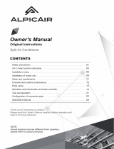
OUTDOOR UNIT
● Please mount the Outdoor unit on stable ground to prevent vibration
and increase of noise level.
● Decide the location for piping after sorting out the different types of
pipe available.
● Open the service valve cover by unscrewing the screws as shown
below.
Gas Leakage Inspection
Please use gas leakage detector
to check if leakage occurs at
the connection of Flare nut as
shown on the right.
If gas leakage occurs, further
tighten the connection to stop
leakage. (Use the detector
provided for R32)
Preparation of Pipe
● Use a pipe cutter to cut the copper pipe.
● Jagged edge will cause leakage.
● Point the side to be trimmed downwards during trimming to prevent copper
chips from entering the pipe.
● Before fl aring, please put on the fl are nut.
Pipe Connection
2
INSTALLATION OF REFRIGERATING PIPES AND AIR REMOVAL
● Recommend to use
R32 fl aring tool.
● When removing fl are nut from the Indoor unit, please ensure to use proper
tooling.
● Prevent pipe from coming in contact with water or working in wet area.
1
Outer
dia.of pipe
6.35 (1/4")
9.52 (3/8")
6.35 (1/4")
9.52 (3/8")
Valve
head cap
Torque N·m
(kgf · cm)
13.7 – 18.6 (140 – 190)
34.3 – 44.1 (350 – 450)
19.6 – 24.5 (200 ~ 250)
19.6 – 24.5 (200 ~ 250)
12.3 – 15.7 (125 ~ 160)
Small dia. side
Large dia. side
Valve core cap
Small dia. side
Large dia. side
CAUTION
CAUTION
!
!
Outer
Diameter (mm)
6.35 (1/4)
9.52 (3/8)
1.0~1.5
1.0~1.5
Clutch type
A (mm)
1.5~2.0
1.5~2.0
Wing nut type
Thickness
(mm)
0.8
0.8
0.0 ~ 0.5
0.0 ~ 0.5
Flare tool for R32
Clutch type
Conventional fl are tool
CONNECTION OF POWER CORD
Removal Of Air From The Pipe And Gas Leakage Inspection
3
Procedures of using Vacuum Pump for Air Removal
AIR REMOVAL
When the meter reaches - 101KPa (-76cmHg)
during pumping, fully tighten the shuttle.
Meter showing pressure
Closed
Manifold valve
Vacuum
pump
Valve
Charge hose
Valve
When pumping starts, slightly loosen the
fl are nut to check of air sucked in. Then
tighten the fl are nut.
As shown in right fi gure, remove the cap of
valve core. Then, connect the charge hose.
Remove the cap of valve head. Connect the
vacuum pump adapter to the vacuum pump
and connect the charge hose to the adapter.
Fully tighten the “Hi” knob of the manifold
valve and completely unscrew the “Lo” knob.
Run the vacuum pump for about 10~15
minutes, then completely tighten the “Lo” knob
and switch off the vacuum pump.
After vacuuming, confi rm that the needle of
the manifold gauge is stable for 3~5 minutes.
Completely unscrew the spindle of the
service valve (at 2 places) in anti-clockwise
direction to allow the fl ow of refrigerant (using
Hexagonal Wrench key).
Re-cap the service valve and tighten using
wrench. Check the cap’s periphery if there is
any gas leakage. The task is then completed.
Remove the charge hose and tighten the cap
of valve core. Check the cap’s periphery if
there is any gas leakage.
Vacuum
pump
adapter
Checking for the electric source and the
voltage range
● Before installation, the power source must be checked and
necessary wiring work must be completed. To make the wiring
capacity proper, use the wire gauge list below for the wiring from
house distribution fuse box to the outdoor unit in consideration of
the locked rotor current.
● Investigate the power supply capacity and other electrical conditions
at the installation location.
Depending on the model of room air conditioner to be installed,
request the customer to make arrangements for the necessary
electrical work etc.
The electrical work includes the wiring work up the outdoor. In
localities where electrical conditions are poor, use of a voltage
regulation is recommended.
THIS APPLIANCE MUST BE EARTHED.
WARNING
WARNING
When removing the connecting wires for the
indoor unit, please remove the low cover panel
in front of the unit.
● The naked part of the wire core should be
10 mm fi x it to the terminal tightly. Then
try to pull the individual wire to check if
the contact is tight. Improper insertion may
burn the terminal.
● Be sure to use only wire specifi ed for the
use of air-conditioner.
● Please refer to the manual for wire
connection and the wiring technique
should meet the standard of the electrical
installation.
● There is an AC voltage drop between the
LN terminal if the power is on. Therefore,
be sure to remove the plug from its socket.
Wire length
up to 20m
Wire gauge
1.5mm2
IMPORTANT
IMPORTANT
13A
Fuse Capacity
!
CAUTION
Note:
● Outdoor supply cords shall not be
lighter than polychloroprene sheathed
fl exible cord, 60245 IEC 57.
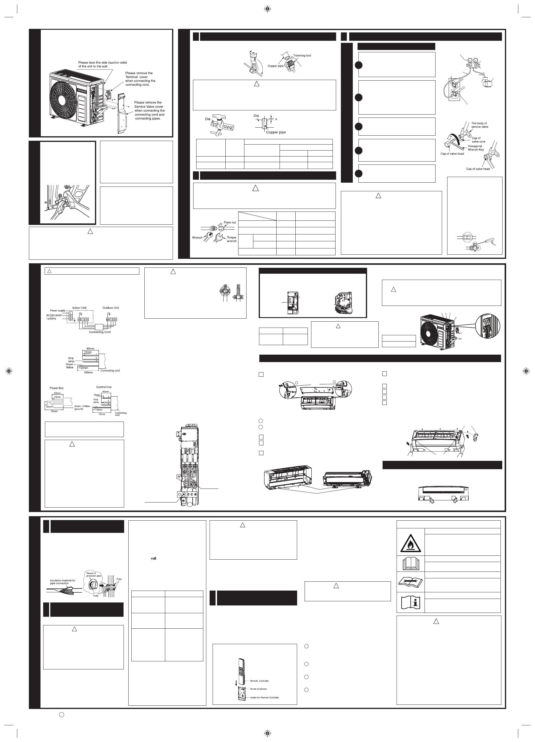
Wiring Of The Indoor Unit
●
For wire connection of the Indoor unit, you need to remove front
panel and electrical cover.
Method to remove front panel
●
Please refer to Instruction Manual – “Removing the Front Panel”
under “Cleaning of Front Panel”.
Connect the
earth cord
After remove the
screw and band, put
the connecting cords
and fi x the band
with screw.
Method to remove electrical cover
● Remove the screw and electrical cover.
● Insert the connecting cord (1, 2, 3) from the back of unit.
● Fixed the wire to terminal wires fi rmly as shown as below.
Connecting cord
Electrical cover
Screw
WARNING
● If you cannot attach the side plate due to the connecting
cord, press the connecting cord in direction to the front
panel to fi x it.
● Be sure that the hooks of the side plate is fi xed in certainly.
Otherwise water leakage may occur and this causes short
circuit or faults.
Wiring Of The Outdoor Unit
● Please remove the side plate for wire connection.
Procedures of Wiring
In case that power is supplied from Indoor Unit
WARNING
● Use the two spanners on
the service valve nuts to
tighten and loosen so that
the service valve will not
deform. Gas leak from the
crushed part, stagnation,
touching fi re, rarely cause
ignition.
● Prevent moisture from entering pipe connection.
● Refrigerating machine oil not be applied to the outside
of the fl are.
When refrigerating oil is applied to the outside of the
fl are, cracking of the fl are nut, destruction of the fl are
and gas leakage may occur due to the excessive
tightening of the fl are nut.
● When using the control valve, do not use deteriorated
packing. And, do not overtighten the steering wheel.
Gas leakage from the service valve part, stagnation,
touching fi re, rarely cause ignition.
CAUTION
!
!
!
● Leave some space in the connecting cord
for maintenance purpose and be sure to
secure it with the cord band.
● Secure the connecting cord along the
coated part of the wire using the cord
band. Do not exert pressure on the wire
as this may cause overheating or fi re.
● Supply cords, current- carrying conductors
become taut before earthing conductor, if
the cord slips out of the cord band.
23
Earth terminal
1
1
2
3
4
5
!
Must install air conditioner according to the electrical installation
standards for Thailand of the Engineering Institue of Thailand
under The Royal Patronage of His Majesty (the King).
PURGING OF REFRIGERANT IS
PROHIBITED
Purging of refrigerant will cause the unit
to be lacked of refrigerant which may
affect the capacity performance and
lead to severe dew formation causing
problem such as dew water drop or
splashing from the unit.
When connecting pipes. If you tighten
the flare nut by excess torque, the
service valve on the small pipe side
may be broken.
The fl are nut on the small pipe side
should be torqued to 122 - 165lbf.in
(140 - 190kgf.cm).
BURST HAZARD
Do not allow air, etc. to get into refrigerant cycle (piping)
RISK OF EXPLOSION
Compressor must be stopped before removing refrigerant pipes.
All service valve must be fully closed after pumping down operation.
Outdoor Unit
Detail of cutting the connecting cord
Indoor Unit
HOW TO REMOVE OR ATTACH THE FRONT COVER
How to Remove the Front Cover
1 Remove the front panel
1 Push the end of the right-side arm outward to release the tab.
2 Move the left-side arm outward to release the left tab, and then pull the
panel towards you.
2 Remove the fi lters.
3 After removing 3 screws, remove the cover of electric box, pull the center
of the front cover towards you and release the claws.
4 Pull the side faces (lower sections) of the front cover towards you as
shown in the fi gure and remove the cover.
Claw
Arm
Move
How to Attach the Front Cover
1 After installing the front cover onto the unit, hook three claws at upper
side of the cover securely. Then, push the center of the front cover to
lock the claws.
2 Assemble the cover of electric box.
3 Tighten the 3 screws.
4 Install the fi lter.
5 Attaching the Front Panel
● Insert the shaft of the left arm along the step on the unit into the hole.
● Securely insert the shaft of the right arm along the step on the unit
into the hole.
● Make sure that the front panel is securely attached, and then close
the front panel.
Claw Claw Claw
Screw
Cover
Screw
HOW TO REMOVE INDOOR UNIT
●
Push up the (PUSH) sections at the bottom of the indoor unit and pull the
bottom plate towards you. Then the claws are released from the stationary
plate. (The (PUSH) sections are indicated by 2 arrows as below fi gure)
[PUSH] mark positions
<
IA2180: B
>
FINAL STAGE OF INSTALLATION
Insulation And Maintenance
Of Pipe Connection
1
● The connected terminals should be completely sealed with
heat insulator and then tied up with rubber strap.
● Please tie the pipe and power line together with vinyl tape
as shown in the fi gure showing the installation of Indoor
and Outdoor units. Then fi x their position with holders.
● To enchance the heat insulation and to prevent water
condensation, please cover the outdoor part of the drain
hose and pipe with insulation pipe.
● Completely seal any gap with putty.
● The remote controller can be placed in its holder which is fi xed
on wall or beam.
● To operate the remote controller at its holder, please ensure
that the unit can receive signal transmitted from the controller
at the place where the holder is to be fi xed. The unit will beep
when signal is received from the remote controller. The signal
transmission is weaken by the fl uorescent light. Therefore, during
the installation of the remote control holder, please switch on the
light, even during day time, to determine the mounting location
of the holder.
Pump Down Method When Reuse
Existing Piping (R410A Model) for R32
Model
Proper Pump Down Method
1 Operate air conditioner at cooling mode for 10~15 minutes
Most Important Process
Purpose: To make the oil & refrigerant mix together. They
are in separated condition when air conditioner is stopped.
2 After 10~15 minutes of pre operation, close 2s valve. After
3 minutes, close 3s valve.
Mixed refrigerant & oil will be collected into outdoor unit.
3 Take out air conditioner unit.
It is advisable to fl ush the piping with R32 to avoid any
contamination remain before new installation.
4 Install New Refrigerant air conditioner
● Compressor oil of R410A model is insoluble in compressor
oil of R32 model. The mixing of compressor oil may cause
damage of compressor.
Possibility of Mixing
● Reuse of piping of R410A model is dangerous because of its
compressor oil.
● When reuse piping of R410A model, pump down must be carried
out properly to ensure compressor oil which is remained inside
piping is collected away.
Power Source And
Operation Test
3
Power Source
CAUTION
!
● Please use a new socket. Accident may occur due to
the use of old socket because of poor contact.
● Please plug in and then remove the plug for 2 – 3
times. This is to ensure that the plug is completely
plugged into the socket.
● Keep additional length for the power cord and do not
render the plug under external force as this may cause
poor contact.
● Do not fi x the power cord with U-shape nail.
Operation Test
● Please ensure that the air conditioner is in normal
operating condition during the operation test.
● Explain to your customer the proper operation procedures
as described in the user’s manual.
The controller should be insert from top into bottom side
of the holder as shown below.
Reuse of piping R410A model only apply if previous model
is Hitachi and proper pump down method is used.
CAUTION
!
To Reuse Old Piping
● Piping of R410A model can be reused only when air-conditioner
is properly pumped down.
● The purpose of pump down is to collect back the compressor
oil (which is mixed with refrigerant and circulating inside
refrigeration cycle) properly into the outdoor unit of air
conditioner.
WARNING
Explanation of symbols displayed on unit
CAUTION
CAUTION
CAUTION
● Do not use means to accelerate the defrosting process or to
clean, other than those recommended by the manufacturer.
Any unfi t method or using incompatible material may cause
product damage, burst and serious injury.
● The appliance/pipe-work shall be stored in a well ventilated room
with fl oor area larger than Amin(m2) and without any continuously
operating ignition source. Keep away from open fl ames, any
operating gas appliances or any operating electric heater. Else,
it may explode and cause injury or death.
● The appliance/pipe-work shall be installed, and/or operated
in a room with fl oor area larger than Amin(m2) and keep away
ignition sources, such as heat/spark/open fl ame or hazardous
areas such as gas appliances, gas cooking, reticulated gas
supply systems or electric cooking appliances, etc.
● Do not pierce or burn as the appliance is pressurized. Do not
expose the appliance to heat, fl ame, sparks, or other sources
of ignition. Else, it may explode and cause injury or death.
WARNING
!
This symbol shows that this equipment uses a
fl ammable refrigerant.
If the refrigerant is leaked, together with an
external ignition source, there is a possibility
of ignition.
This symbol shows that the Operation
Instructions should be read carefully.
This symbol shows that a service personnel
should be handling this equipment with
reference to the Installation Manual.
This symbol shows that there is information
included in the Operation Manual and/or
Installation Manual.
Installation Of Remote
Controller
2
Perform a trial run to make sure that the air
conditioner operates properly.
1. Operate with Cooling Mode.
2. Press the ROOM TEMPERATURE button to set the
temperature to 16°C for cooling mode. Set the fan
speed to “ ” (High).
3. Operate the air conditioner for at least 20 minutes
and make sure that the air from the air conditioner
is cool.
4. Press the ON/Off button on the remote controller to
make sure that the air conditioner stops running.
● If the indication lamps of the indoor unit blink with
sounding the buzzar during the operation test,
perform a check following the procedures below.
Trial run ❖ Be sure to measure the
supply voltage before
connecting the power cord
into the power outlet.
● To reset the power supply by switching the circuit
breaker OFF, and ON only after
● waiting for at least 5 minutes; or
● pressing the temporary switch button only once
while the power is OFF.
Indicator Blinking Mode What to check
Make sure that the voltage
of the power outlet is
correct according to the
product specifi cation.
Make sure that the
connecting cord is
connected correctly and
securely.
Make sure that the spindles
of both service valves
are open. (Outdoor fan
might operate for near 15
minutes after the operation
stop for the protection. For
the reoperation at that
case, do it after outdoor
fan will stop.)
All indicators blink
once repeatedly
All indicators blink
twice repeatedly.
All indication lamps
blink three times
repeatedly.
● If connecting cord cable connection is not correct,
the timer lamp may blink 12 times or blink 21
times during the operation test. If this occurs,
check the connection of the connecting cord
cable. Please check the service guide for details.
CAUTION
!
● Don’t operate for over 5 minutes with the situation that the
spindle of the service valve is closed. This will cause the
defect.
● Don’t operate by Cool Mode or Dry Mode with the door
and windows opened, (the room humidity is always above
80%) for a long period of time. Water will condense and
drip down occasionally.
This will wet your furniture.
● Explain to your customer the proper operation procedures as
described in the user‘s manual.
● If the indoor unit won‘t operate, check the cable for correct
connection.
● Turn on the lamp in the room where the indoor unit is installed
and check the remote controller for normal operation.