AV-30 Quick Reference Card
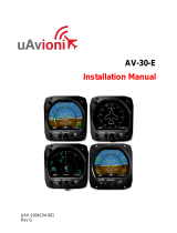
AI Normal Display State
Basic Data
▪Blank
▪DG Heading
▪IAS
▪Altitude
▪Baro Set
▪AoA
▪Vertical Speed
▪G Load
▪Bus Volts
▪Set Altitude
If Temp Probe
▪OAT
▪TAS
▪DALT
If GPS Connected
▪Waypoint ID
▪Distance To
▪Ground Speed
▪Track
▪XTE
▪DTRK
▪Bearing To
If Autopilot Connected
▪Set Vertical Speed Bug
(overlaid on Vertical
Speed)
UNIT FUNCTION
FUNCTION LOCK
PITCH TRIM
ROLL TRIM
SLIP TRIM
OAT TRIM
IAS TRIM
ALT TRIM LO
ALT TRIM HI
PITOT ZERO
AOA FUNC
IAS UNITS
TAS UNITS
IAS VSpeed Limits:
VS0, VS1, VFE, VNO,
VNE, VMC, VYSE
BARO UNITS
TEMP UNITS
GPS NAV SRC
SERIAL 1
SERIAL 2
SERIAL 3
SERIAL 4
AID MODE
AVMAG INSTL
AVMAG CAL
AVMAG YAW
MAG MONITOR
VIBE MONITOR
GYRO CAL
INT MAG CAL
DEMO MODE 2
RESET AVLINK
BEACONX GTM
SW P/N
SW VERSION
SW CHECKSUM
BL VERSION
SW CERT
UI Style
UI Font
Alert Volume
AoA Alert Enable
AoA Alert Thresholds 5
G Alert Enable
G Alert Thresholds
Roll Alert Enable
Roll Alert Thresholds
GPS Track Stabilization
HOURS
1To access the installation menu,
push-and-hold the rotary knob
button while applying power.
2 While in Demo Mode, hold
both left and right buttons to
reset unit to factory defaults.
Push left button 2x
SETUP
ROT TO SEL
Push left button 3x
INSTALL
ROT TO SEL
6Not all values can be placed in
every field (IAS, Altitude and Baro
Setting only allowed in certain
fields). Some values are
implemented with graphical
indicators, other with textual
fields.
Push left button 1x
EDIT FIELDS
SEL FIELD
5 AoA limits will be grayed out
unless rotary knob is pushed
while applying power. See 1
SET BARO Rotate/Push 1x ⚫Rotate to trim ⚫Push to set
DG ADJ 3Push 2x ⚫Rotate to trim ⚫Push to set
HDG BUG Push 3x ⚫Rotate to trim ⚫Push to set
Hold button down to align with current heading
SET ALT Push 4x ⚫Rotate to desired alt ⚫Push to set
SET VS 4Push 5x ⚫Rotate to desired VS ⚫Push to set
AUTOPILOT 4Push 6x ⚫Rotate to desired Mode ⚫Push to set
- A Given Entry Will Not Be Available If Not Configured For Display
- Push and Hold to Toggle AI/DG/MFD Mode (if not locked)
3With AV-Mag, DG ADJ is last available Push to set option
4Only available when autopilot configured
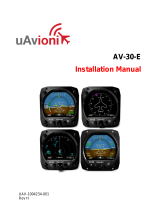
Select Current Page
Three Customizable Pages 1:3, 2:3, 3:3, AI
AI - Decluttered Attitude Indicator/Transponder Control
Push RIGHT button to change page
Hold RIGHT button for brightness setting
Battery
State
FOR REFERENCE ONLY
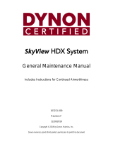
EDIT FIELDS MENU
Highlighted In Black.
7 editable fields per page,
20 possible values 6
INSTALL MENU1
SETUP MENU
www.uavionix.com/support
Support: (844) 827-2372
UAV-1005760-001 Rev C