Page is loading ...

UAV-1004233-001
Rev. H
AV-30-E
Pilot’s Guide

UAV-1004233-001, AV-30-E Pilot’s Guide
Rev. H Page 2
© 2020 - 2023 uAvionix Corporation. All rights reserved.
uAvionix Corporation
Bigfork, MT
www.uavionix.com
support@uavionix.com
Except as expressly provided herein, no part of this guide may be
reproduced, transmitted, disseminated, downloaded, or stored in any
storage medium, for any purpose without the express written permission of
uAvionix. uAvionix grants permissions to download a single copy of this
guide onto an electronic storage medium to be viewed for personal use,
provided that the complete text of this copyright notice is retained.
Unauthorized commercial distribution of this manual or any revision hereto
is strictly prohibited.
uAvionix® and Ping® are registered trademarks of uAvionix Corporation
and may not be used without express permission of uAvionix.
AV-30, AV-30-E, AV-30-C, AV-Link-E, AV-Link-C, AV-Mag, BeaconX,
tailBeaconX, and skyBeaconX are trademarks of uAvionix Corporation and
may not be used without express permission of uAvionix.
Patents uavionix.com/patents

UAV-1004233-001, AV-30-E Pilot’s Guide
Rev. H Page 3
1 Revision History
Revision
Date
Comments
A.
6/2/2020
Initial release.
B.
5/4/2021
Add AV-Link feature.
Add traffic display feature.
Add transponder control feature.
C
5/20/2021
Section 7.5.5 Correction of non-slaved DG
D
7/22/2021
Added features of tailBeaconX and software
update aiding features.
E
1/5/2022
Added AeroCruze 100/TruTrak Vizion autopilot
control feature.
F
4/12/2022
Added AV-Mag external magnetometer.
G
10/11/2022
Added Set Altitude (SALT) visual alert.
Changed TRUTRAK to AEROCRUZE. Added
Trio PRO PILOT autopilot support. Added AV-
Link-E reset feature. Added direct turn
adjustment of barometer and heading bug.
Added overlay elements on DG screens to
support altitude controlling autopilots. Modified
heading bug display to synchronize with
autopilot usage. Modified PUSH-SET menu
sequences to better support autopilot inputs.
Missing magnetometer calibration now flagged
with “MAG CAL” rather than “NO MAG”. Added a
“zero out” action of the DG adjustment if using
AV-Mag. Added table of checks and alerts for
stored parameter integrity. Added three new
autopilot heading modes and descriptions.
Added GPS error messages table. Added AI

UAV-1004233-001, AV-30-E Pilot’s Guide
Rev. H Page 4
screenshots illustrating 1:3, 2:3, 3:3 default
screens.
H
2/27/2023
Updated Angle Of Attack Limit setting
instructions to match the AV-30-C Pilot’s Guide.
Updated CRC check splash messages.
Update AV-Link for latest release (0.3.0) and
new IP (192.168.5.1).

UAV-1004233-001, AV-30-E Pilot’s Guide
Rev. H Page 5
2 Warnings / Disclaimers
All device operational procedures must be learned on the ground.
uAvionix is not liable for damages arising from the use or misuse of this
product.
This equipment is classified by the United States Department of
Commerce's Bureau of Industry and Security (BIS) as Export Control
Classification Number (ECCN) 7A994.
These items are controlled by the U.S. Government and authorized for
export only to the country of ultimate destination for use by the ultimate
consignee or end-user(s) herein identified. They may not be resold,
transferred, or otherwise disposed of, to any other country or to any
person other than the authorized ultimate consignee or end-user(s), either
in their original form or after being incorporated into other items, without
first obtaining approval from the U.S. Government or as otherwise
authorized by U.S. law and regulations.

UAV-1004233-001, AV-30-E Pilot’s Guide
Rev. H Page 6
3 Limited Warranty
uAvionix products are warranted to be free from defects in material and
workmanship for two years from the installation of AV-30-E on the aircraft.
For the duration of the warranty period, uAvionix, at its sole option, will
repair or replace any product which fails in normal use. Such repairs or
replacement will be made at no charge to the customer for parts or labor,
provided that the customer shall be responsible for any transportation cost.
Restrictions: This warranty does not apply to cosmetic damage,
consumable parts, damage caused by accident, abuse, misuse, fire or
flood, theft, damage caused by unauthorized servicing, or product that has
been modified or altered.
Disclaimer of Warranty: IN NO EVENT, SHALL UAVIONIX BE LIABLE
FOR ANY INCIDENTAL, SPECIAL, INDIRECT OR CONSEQUENTIAL
DAMAGES, WHETHER RESULTING FROM THE USE, MISUSE, OR
INABILITY TO USE THE PRODUCT OR FROM DEFECTS IN THE
PRODUCT. SOME STATES DO NOT ALLOW THE EXCLUSION OF
INCIDENTAL OR CONSEQUENTIAL DAMAGES, SO THE ABOVE
LIMITATIONS MAY NOT APPLY TO YOU.
Warranty Service: Warranty repair service shall be provided directly by
uAvionix. Proof of purchase for the product from uAvionix or authorized
reseller is required to obtain and better expedite warranty service.
Please email or call uAvionix support with a description of the problem you
are experiencing. Also, please provide the model, serial number, shipping
address and a daytime contact number.
You will be promptly contacted with further troubleshooting steps or return
instructions. It is recommended to use a shipping method with tracking and
insurance.

UAV-1004233-001, AV-30-E Pilot’s Guide
Rev. H Page 7
4 Table of Contents
1 Revision History ................................................................................. 3
2 Warnings / Disclaimers ....................................................................... 5
3 Limited Warranty ................................................................................ 6
4 Table of Contents ............................................................................... 7
5 AV-30-E System Information ............................................................ 11
5.1 System Description .................................................................... 11
5.2 System Functions ...................................................................... 12
6 Unit Interfaces .................................................................................. 14
6.1 Aircraft Systems Interfaces ........................................................ 14
6.2 Power Input (Required) ............................................................. 15
6.3 Pitot and Static Interfaces (Required) ........................................ 16
6.4 GPS Interface (Optional) ........................................................... 16
6.5 OAT Probe (Optional) ................................................................ 17
6.6 Audio Output (Optional) ............................................................. 17
6.7 Transponder Control (Optional) ................................................. 17
6.8 AV-Link-E Interface (Optional) ................................................... 17
6.9 Magnetometer Aiding (Optional) ................................................ 18
6.10 Autopilot (Optional) .................................................................... 18
7 User Interface ................................................................................... 20
7.1 Startup and Common Controls .................................................. 20
7.2 “PUSH-SET” Control ................................................................. 21
7.3 Direct-Turn ................................................................................ 22
7.4 User Interface Customization .................................................... 22
7.4.1 AI Mode Customization ........................................................ 24
7.4.2 Edit Presented Data ............................................................. 26
7.5 AI Mode Display Components ................................................... 26
7.5.1 Basic Components ............................................................... 26
7.5.2 Customizable Data Overlay Fields ....................................... 27

UAV-1004233-001, AV-30-E Pilot’s Guide
Rev. H Page 8
7.5.3 Attitude / Slip ........................................................................ 28
7.5.4 Airspeed Indicator ................................................................ 29
7.5.5 Flight Direction Indicator ...................................................... 31
7.5.6 Barometric Corrected Altitude Indicator ................................ 31
7.5.7 AoA Indication ...................................................................... 32
7.5.8 Vertical Trend Indicator ........................................................ 33
7.5.9 G-Load Indicator .................................................................. 35
7.5.10 Text Fields ........................................................................... 35
7.5.11 Accessing Reversionary AI .................................................. 36
7.6 DG Mode Display Components ................................................. 36
7.6.1 DG Mode Customization ...................................................... 36
7.6.2 Non-Slaved Heading Mode .................................................. 36
7.6.3 GPS HSI Mode .................................................................... 37
7.6.4 GPS ARC Mode ................................................................... 38
7.6.5 Operational Aspects ............................................................. 38
7.6.6 Accessing Reversionary AI .................................................. 40
7.7 AI / DG Displayable Parameters ................................................ 40
7.8 MFD Mode ................................................................................. 42
7.8.1 Features............................................................................... 42
7.8.2 Firmware Update ................................................................. 43
7.8.3 Display Functions ................................................................. 44
7.8.4 Display Zoom ....................................................................... 44
7.8.5 Target Relative Altitude ........................................................ 45
7.8.6 Target Airspeed ................................................................... 46
7.8.7 Target Tracking Function ..................................................... 46
7.8.8 Accessing Reversionary AI .................................................. 47
7.8.9 Traffic Mode Configuration ................................................... 48
7.9 Reversionary AI ......................................................................... 51
7.10 Transponder Control .................................................................. 51

UAV-1004233-001, AV-30-E Pilot’s Guide
Rev. H Page 9
7.10.1 Status .................................................................................. 51
7.10.2 Changing Squawk ................................................................ 52
7.10.3 Changing Flight ID ............................................................... 53
7.10.4 Changing Transponder Mode .............................................. 53
7.10.5 To Send IDENT ................................................................... 53
7.10.6 Quick Squawk VFR .............................................................. 53
7.11 Brightness Menu ....................................................................... 54
8 User Interface and Font Style Options .............................................. 55
9 Alerts and Alert Limits ...................................................................... 56
9.1 Airframe Envelope Alerts ........................................................... 56
9.2 Altitude Alert .............................................................................. 57
10 Internal Battery Operation ................................................................ 58
10.1 General ..................................................................................... 58
10.2 Battery Transition Logic ............................................................. 58
10.2.1 Power-On Self-Test (Pre-Flight) ........................................... 58
10.2.2 Power Loss, Airspeed Above 40 Knots (In-Flight) ................ 59
10.2.3 Power Loss, Airspeed Below 40 Knots (On-Ground)............ 59
10.3 Battery Charge Status ............................................................... 59
11 AoA Operation and Configuration ..................................................... 61
11.1 Operational Methodology........................................................... 61
11.2 Configured Limits....................................................................... 62
11.3 Stable Flight Conditions ............................................................. 63
11.4 Setting AoA Upper Limit ............................................................ 63
11.5 Setting AoA Lower Limit ............................................................ 64
11.6 AoA Alert Types and Thresholds ............................................... 65
11.7 Flap Setting Observations ......................................................... 65
12 Setup Menu ...................................................................................... 67
12.1 Pilot-Accessible Setup Menu ..................................................... 68
12.2 Non-Pilot Accessible Install Menu .............................................. 69

UAV-1004233-001, AV-30-E Pilot’s Guide
Rev. H Page 10
13 AV-Link-E ......................................................................................... 70
13.1 Overview ................................................................................... 70
13.2 Additional Required Equipment ................................................. 70
13.3 Connecting ................................................................................ 71
13.4 Home Page ............................................................................... 72
13.4.1 Settings ................................................................................ 72
13.4.2 Status .................................................................................. 72
13.4.3 Device Information ............................................................... 72
13.4.4 Navigating to Other Pages ................................................... 73
13.5 Wi-Fi Settings Page ................................................................... 73
13.5.1 ADS-B Receiver Settings ..................................................... 73
14 Autopilot ........................................................................................... 76
14.1 Selecting Heading ..................................................................... 77
14.2 Selecting Altitude ....................................................................... 77
14.3 Selecting Vertical Speed ........................................................... 77
14.4 Selecting Autopilot Mode ........................................................... 78
15 Stored Data Integrity Check ............................................................. 79
16 Operating Limits & System Specifications ........................................ 80

UAV-1004233-001, AV-30-E Pilot’s Guide
Rev. H Page 11
5 AV-30-E System Information
5.1 System Description
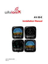
The uAvionix AV-30-E is a fully digital multi-mode instrument that mounts
in the legacy 3-1/8” round instrument panel. It can be field configured as
either an Attitude Indicator (AI), a Directional Gyro (DG) indicator or Multi-
Function Display (MFD). It is fully self-contained with dual-precision
inertial and pressure sensors and allows for a wide variety of pilot
customization. Transponder control is available in both AI and DG modes.
Figure 1 - AV-30-E Multi Mode AI/DG/MFD – Basic Display
When configured as an AI, primary attitude and slip are always displayed.
The unused portions of the display area can be customized by the pilot to
show a variety of textual and graphical data overlay fields. Three pages
may be customized by the pilot while a fourth page presents a fully
decluttered view of only attitude and slip, while optionally presenting
transponder controls.
When configured as a Directional Gyro (DG), direction of flight information
is presented. The flight direction can be configured to be presented as a
non-slaved heading, aided by an optional internal magnetometer, or
inertially stabilized GPS track when connected to an external GPS
navigator. Multiple display presentations, including compass rose, GPS
HSI, and GPS Arc views can be selected by the pilot. The unused
portions of the display area can similarly be configured for a variety of
textual data-overlays.

UAV-1004233-001, AV-30-E Pilot’s Guide
Rev. H Page 12
When configured as a Multi-Function Display (MFD) and connected to AV-
Link-E, live airborne and ground traffic from a supported Wi-Fi capable
Automatic Dependent Surveillance-Broadcast (ADS-B) receiver is
available.
A presentation of the decluttered attitude and slip, optionally with
transponder controls, is available as the last presentation in DG and MFD
mode.
In AI or DG operating modes, the pilot may select from multiple visual
styles which are intended to improve visual compatibility with legacy
aircraft instrumentation and preserve the look-and-feel of older aircraft
applications.
A wide variety of supplemental functions, including audio alerting, derived
angle of attack presentation, G-load display, and more are provided. An
internal, rechargeable battery allows for operation for a nominal 1 hour in
the event of aircraft power loss and 30 minutes minimum under all
operating temperature conditions.
When installed as a non-required instrument (not replacing the existing
approved AI or DG), the functional mode of the unit can be toggled
between AI and DG by pressing and holding the rotary knob for 3 seconds.
5.2 System Functions
Primary Functions
- Primary Attitude (AI Mode)
- Primary Slip (AI Mode)
- Primary Direction of Flight indication (DG Mode)
Supplemental Functions
- Indicated Airspeed
- Altitude
- V-Speeds
- Angle of Attack
- Vertical Trend
- Vertical Speed
- Set Altitude (SALT)
- Set Vertical Speed (SVS)

UAV-1004233-001, AV-30-E Pilot’s Guide
Rev. H Page 13
- Heading
- Bus Voltage
- G Load
- Outside Air Temperature
- True Airspeed
- Density Altitude
- GPS Navigator/Waypoint Data
- GPS Navigator Nav Data
- GPS Navigator Route Line
- Heading Bug
- Traffic page (requires AV-Link-E)
- Transponder control (AI / DG / MFD Mode)
- Autopilot control
Audio and Visual Alerting Functions
- AoA Alerting
- G Limit Alerting
- Excessive Roll Alerting
- Set Altitude Alerting
Miscellaneous Functions
- Internal Battery Operation
- Auto/Manual Brightness

UAV-1004233-001, AV-30-E Pilot’s Guide
Rev. H Page 14
6 Unit Interfaces
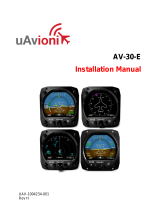
6.1 Aircraft Systems Interfaces
The following describes each of the AV-30-E system interconnects for both
the AI, DG and MFD installation configurations. Note that, as shown in
Figure 2 – AV-30-E Aircraft Systems Interfaces – AI Mode, that some
interfaces are optional and may not be available in each installation.
Figure 2 – AV-30-E Aircraft Systems Interfaces – AI Mode
When installed as a DG, no audio outputs are supported, and some air
data related parameters are only available when the optional OAT probe is
equipped.

UAV-1004233-001, AV-30-E Pilot’s Guide
Rev. H Page 15
Figure 3 – AV-30-E Aircraft Systems Interfaces – DG Mode
6.2 Power Input (Required)
Power input is required in both AI, DG and MFD configurations and each
unit has a dedicated circuit breaker. The power input is internally
connected, and diode protected with the unit’s internal battery via a
processor-controlled switch. This architecture allows the unit to continue
operation if external power fluctuates or is completely lost.
When external power is supplied to the AV-30-E, there is no mechanism to
turn the unit off. When operating on battery, the unit may be forced off by
pressing the left and right buttons simultaneously until the unit shuts off.
See §10 - Internal Battery Operation for more information.
The AV-Link-E accessory is not powered by the AV-30-E
internal battery. Wi-Fi traffic data provided to the MFD mode
will be unavailable during a power loss.

UAV-1004233-001, AV-30-E Pilot’s Guide
Rev. H Page 16
6.3 Pitot and Static Interfaces (Required)
Pitot and static connections are required for AI, DG, and MFD mode.
Airspeed, altitude, derived angle of attack (AoA), True Airspeed (TAS),
Density Altitude (DALT), DG heading, and traffic altitude all require pitot
and static connections as they are based on either altitude or airspeed
measured from those connections.
When installed as an MFD, the pitot and static connections are required
for traffic relative altitude. If unconnected, incorrect relative altitudes may
be displayed.
6.4 GPS Interface (Optional)
The Global Positioning System (GPS) interface is an optional RS-232
serial input that is compatible with the industry standard Aviation output
provided by most panel mounted GPS units or NMEA serial interfaces
provided by most hand-held GPS units.
The GPS navigator output is a text/binary protocol that contains situational
awareness information such as ground speed, track, distance to
destination, cross track, etc., and is typically utilized by remote
mapping/display products to provide additional pilot awareness.
This output does not provide IFR compliant lateral or vertical guidance,
therefore all deviation related data presented is for VFR operations only.
The AV-30-E does not alter the data obtained from the GPS navigator and
simply displays the received data in a textual or graphical format as
configured by the pilot.
The AV30-E can use a parallel input from a BeaconX to drive its GPS
functions. A second AV-30-E is required to act as the BeaconX
Transponder Controller as per section 6.7. Only one AV-30-E may receive
transponder data but both may receive GPS data from a single BeaconX.

UAV-1004233-001, AV-30-E Pilot’s Guide
Rev. H Page 17
6.5 OAT Probe (Optional)
The optional Outside Air Temperature (OAT) probe interface is compatible
with the industry standard “Davtron” (C307PS) probe which is mounted
external to the aircraft. OAT data is available as a textual data overlay and
is used to compute temperature dependent data such as True Airspeed
(TAS) and Density Altitude (DALT). Each AV-30-E requires a dedicated
probe. A single OAT probe cannot be shared between multiple units.
The OAT probe is automatically detected by the system, and when
present, allows temperature related parameters to be selected for display.
If the OAT probe is not detected, display of these parameters is inhibited.
6.6 Audio Output (Optional)
The optional audio output provides audio alerts for the various alerting
conditions. This output is typically connected to the aircraft’s non-switched
audio input on the audio panel. Audio alerting thresholds and alert
enablement are configured by the pilot in the Setup Menu.
Audio alerting is only supported when configured as an AI.
6.7 Transponder Control (Optional)
The AV-30-E has the option of being the control interface for select
uAvionix transponders (including the BeaconX family). This provides
pressure altitude, mode, squawk code and IDENT information to the
transponder, and displays status and annunciations from the transponder.
The transponder is not powered by the AV-30-E internal battery.
Transponder operations will be unavailable during a power loss.
Note that the BeaconX output can be shared in parallel between two AV-
30-E devices. One device must act as the Transponder Controller and the
other may use the BeaconX as a GPS-only input.
6.8 AV-Link-E Interface (Optional)
The AV-30-E has the option of displaying ADS-B traffic using AV-Link-E as
an integrated Wi-Fi bridge that allows for communication between AV-30-E

UAV-1004233-001, AV-30-E Pilot’s Guide
Rev. H Page 18
and Wi-Fi capable ADS-B receivers. The AV-30-E will display a separate
navigational page with traffic when configured and connected to a
supported receiver.
The AV-Link-E accessory is not powered by the AV-30-E
internal battery. Wi-Fi traffic data provided to the MFD mode
will be unavailable during a power loss.
6.9 Magnetometer Aiding (Optional)
Two magnetometer aiding devices are available; the AV-Mag external
magnetometer and the internal magnetometer. Support for the AV-Mag
external magnetometer is available in software version 2.3.0 or later and
requires installation in the aircraft. If the AV-30-E is equipped with an
internal magnetometer it will be automatically detected by software in
versions 2.1.1 and later. Both types of magnetometers require calibration
before use. Only one magnetometer can be used at a time. See Section
13 of the AV-30-E Installation Manual UAV1004234-001 for details on how
to calibrate either of the AV-30-E magnetometers.
The AV-Mag is powered by the AV-30-E. During a power loss, the
AV-Mag will be powered by the AV-30-E internal battery and
continue to provide heading data.
6.10 Autopilot (Optional)
The AV-30-E has the option to act as an altitude and direction control input
for the BendixKing AeroCruze 100/xCruze 100/TruTrak Vizion (385 and
PMA) autopilot or the Trio ‘Pro Pilot’ autopilot. The autopilot and AV-30-E
are connected to one another via half duplex RS-232 serial.
The AV-30-E sends a Set Altitude (SALT), a current altitude, a Set Vertical
Speed (SVS), a desired direction, and a current direction to the autopilot.
The pilot controls these via the center knob PUSH-SET menu and displays
the data via graphical or textual overlay fields.

UAV-1004233-001, AV-30-E Pilot’s Guide
Rev. H Page 19
There are four autopilot control modes. Each mode uses a different
combination of desired direction and current direction to achieve different
types of flight goals as show in Table 14-1- Autopilot Modes. For further
details on Autopilot control see section 14 Autopilot.

UAV-1004233-001, AV-30-E Pilot’s Guide
Rev. H Page 20
7 User Interface
7.1 Startup and Common Controls
The initial power-on splash screen presents the company logo, unit model
number, and the currently installed software version.
Figure 4 – Splash Screen
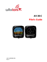
Operation in AI, DG and MFD modes share the following common user
interface controls.
Rotary Knob with
Momentary Push
Left Push Button Right Push Button
(Hold For
Brightness Adjust)
Photo Cell
(Auto Screen
Brightness)
TFT Color Display
Figure 5 - Common User Interface Components
/