Hitachi CP-X870 User manual

Category
Data projectors
Type
User manual
1
LCD Projector CP-X870
USER'S MANUAL
USER'S MANUAL Vol.2 (Extended)
Thank you for purchasing this projector.
• The information in this manual is subject to change without notice.
• The manufacturer assumes no responsibility for any errors that may appear in this manual
• The reproduction, transmission or use of this document or contents is not permitted without express
written authority.
TRADEMARK ACKNOWLEDGEMENT :
• PS/2, VGA and XGA are registered trademarks of the International Business Machines Corporation.
• Apple, Mac and ADB are registered trademarks of Apple Computer, Inc.
• VESA and SVGA are trademarks of the Video Electronics Standard Association.
• Windows is a registered trademark of Microsoft Corporation.
• All other trademarks are the property of their respective owners.
NOTE
WARNING • Please read the accompanying manual “SAFETY
INSTRUCTIONS” and this “USER'S MANUAL” thoroughly to ensure correct
usage through understanding. After reading, store this instruction manual in a
safe place for future reference.
Page
MULTIFUNCTIONAL SETTINGS ........................................................................2
WHAT TO DO WHEN YOU THINK A MACHINE DEFECT HAS OCCURRED ......8
SPECIFICATIONS .............................................................................................11
WARRANTY AND AFTER-SERVICE................................................................12
.......................................................................................
For "TECHNICAL" see the end of this manual.
CONTENTS
www.touchboards.com 205 Westwood Ave.Long Branch, NJ 07740 1-866-942-6273
www.touchboards.com 205 Westwood Ave.Long Branch, NJ 07740 1-866-942-6273 [email protected]
MAIN Menu
Item Description
BRIGHT
Adjust Brightness: Light Dark
CONTRAST
Adjust Contrast: Strong Weak
ASPECT
Select Aspect Ratio:
At RGB Input or Hi-Vision 1125i(1035i/1080i)/750p of COMPONENT VIDEO
Input:
4:3 16:9
At VIDEO Input, S-VIDEO Input or 525i/525p/625i of COMPONENT VIDEO Input:
4:3 16:9 SMALL
• The SMALL picture may not be displayed correctly with certain input signals.
PICT.POSIT.
Select Picture Position (for 16:9/SMALL Picture):
TOP CENTER BOTTOM
GAMMA
Select Gamma Mode:
NORMAL CINEMA DYNAMIC
MIRROR
Select Mirror Status:
NORMAL H:INVERT V:INVERT H&V:INVERT
LANGUAGE
Select Menu Language:
ENGLISH FRANÇAIS DEUTSCH ESPAÑOL
ITALIANO NORSK NEDERLANDS
POTUGUÊS
MULTIFUNCTIONAL SETTINGS
This device has 8 separate menus: MAIN, PICTURE-1, PICTURE-2, INPUT,
AUTO, SCREEN, OPTION, WIRELESS. Each of these menus is operated using
the same methods. The basic operations of these menus are as follows.
With the MAIN menu, the seven items shown in the Table below can be
performed.
Perform each operation in accordance with the instructions in the Table.
Menu screen display : Press the MENU button.
Menu selection : Use the lever switch to select a menu name, then press the
or ENTER button.
Item selection : Use the lever switch to select an item, then press the or
ENTER button.
Return menu to last previous screen
: Press the button or the ESC button.
Execution of settings and/or adjustments
:
Perform the operation using the lever switch
.
(For further details, read the explanation for each separate menu.)
I
nitialization of settings and/or adjustments
: During operation, press the RESET button.
(Functions that are executed at the same time
as a selection, including H PHASE, LANGUAGE
selection, and ADJUST, will not be reset.)
End menu operations: Press the MENU button, or do not perform any operation for
several seconds.
MAIN Menu
2
Example : MAIN Menu
(BRIGHT)
MENU
: SELECT
MAIN
PICTURE-1
PICTURE-2
INPUT
AUTO
SCREEN
OPTION
WIRELESS
BRIGHT
CONTRAST
ASPECT
PICT. POSIT.
GAMMA
MIRROR
LANGUAGE
12
PICTURE-1 Menu
PICTURE-2 Menu
With the PICTURE-1 menu, the five items shown in the Table
below can be performed.
Perform each operation in accordance with the instructions in the
Table.
With the PICTURE-2 menu, the five items shown in the Table
below can be performed.
Perform each operation in accordance with the instructions in the
Table.
Item Description
COLOR BAL R
Adjust Red Color Balance: Dark Light
COLOR BAL B
Adjust Blue Color Balance: Dark Light
SHARPNESS
Adjust Sharpness (for VIDEO/S-VIDEO): Clear Soft
COLOR
Adjust COLOR (for VIDEO/S-VIDEO/COMPONENT VIDEO):
Dark Light
TINT
Adjust Tint (for VIDEO/S-VIDEO): Green Red
PICTURE-1 Menu
Item Description
V POSITION
Adjust Vertical Position (for RGB): Up Down
H POSITION
Adjust Horizontal Position (for RGB): Left Right
H PHASE
Adjust Horizontal Phase (for RGB/COMPONENT VIDEO):
Right Left
• Adjust to eliminate flicker.
H SIZE
Adjust Horizontal Size (for RGB): Large Small
• If the horizontal size adjustment is excessive, the image may not be displayed
correctly. In such a case, initialize H SIZE with the RESET button.
OVER SCAN
Select Over-scan Ratio (for VIDEO/S-VIDEO/COMPONENT VIDEO):
LARGE MIDDLE SMALL
If you select LARGE, you may note streaking on the top and bottom of the
screen, or flicker. If this is irritating, we suggest you select SMALL.
3
PICTURE-2 Menu
Example : PICTURE1 Menu
(COLOR BAL R)
Example : PICTURE2 Menu
(V POSITION)
MENU
: SELECT
MAIN
PICTURE-1
PICTURE-2
INPUT
AUTO
SCREEN
OPTION
WIRELESS
COLOR BAL R
COLOR BAL B
SHARPNESS
COLOR
TINT
12
MENU
: SELECT
MAIN
PICTURE-1
PICTURE-2
INPUT
AUTO
SCREEN
OPTION
WIRELESS
V POSITION
H POSITION
H PHASE
H SIZE
OVER SCAN
12
MULTIFUNCTIONAL SETTINGS (continued)
INPUT Menu
The three Input menu items listed in the table below can be manipulated. For
RGB input, the reception signal’s horizontal and vertical frequency is displayed
on the initial menu screen. Use the table below as a guide for operation.
4
Example : INPUT Menu
(BNC)
MENU
: SELECT
MAIN
PICTURE-1
PICTURE-2
INPUT
AUTO
SCREEN
OPTION
WIRELESS
BNC
VIDEO
HDTV
SYNC ON G
P. IN P. INPUT
P. IN P. POSIT
RGB
COMPONENT
Item Description
BNC
BNC Pin (R/C
R
/P
R
, G/Y, B/C
B
/P
B
, H, V) function selection:
BNC (RGB) BNC (COMPONENT)
(R) (G) (B) (H) (V) (C
R
/P
R
) (Y) (C
B
/P
B
) ( - ) ( - )
(Pins for RGB) (Pins for COMPONENT)
Selecting BNC (RGB) allows the 5 RGB2 pins (R/C
R
/P
R
, G/Y, B/C
B
/P
B
, H, V) to be
used as RGB signal BNC input as-is.
Selecting BNC (COMPONENT) allows the 3 leftmost RGB2 pins (R/C
R
/P
R
, G/Y,
B/C
B
/P
B
) to be used as the COMPONENT VIDEO input C
R
/P
R
, Y, and C
B
/P
B
pins.
VIDEO
Select Mode of Signal Type (for VIDEO/S-VIDEO):
AUTO NTSC PAL SECAM NTSC4.43
M-PAL N-PAL
When AUTO is selected, the video/ S-video input function under ADJUST ( ) are enabled, and is
executed simultaneously so that the optimum signal mode is selected from among the modes listed above.
Use this function if the image becomes unstable with VIDEO/S-VIDEO. (e.g. The image becomes irregular, or lacks color.)
AUTO mode may not function correctly with a PAL60 signal and certain other signals.
• The AUTO mode operation requires approximately 10 seconds.
For COMPONENT VIDEO, the signal type is identified automatically even if
this function is inactive. For a HDTV signal, refer to the item HDTV below.
HDTV
Select HDTV Signal Mode: 1080i 1035i
If the selected HDTV mode is incompatible with the input signal, the picture may be distorted.
SYNC ON G
On/Off SYNC ON G Mode: TURN ON TURN OFF
Selecting TURN ON turns on the SYNC ON G mode. The SYNC ON G mode
allows reception of SYNC on G.
In the SYNC ON G mode, the picture may be distorted with certain input
signals. In such a case, remove the signal connector so that no signal is
received and turn SYNC ON G off, and then reconnect the signal.
P. IN P. INPUT
P. IN P. screen (*) input signal selection: VIDEO S-VIDEO
Selects the signal displayed on the P. IN P. subscreen.
P. IN P. POSIT
P. IN P. screen (*) display position selection:
Selects the position at which the P. IN P. subscreen is displayed.
INPUT Menu
(*) The P. IN P. (picture-in-picture) function displays the video signal image in a subscreen (P. IN P. screen) on
top of the screen on which the RGB signal image is being displayed. (See “Displaying Child Window” Vol.1
.)
5
24
5
AUTO Menu
With the AUTO menu, the four items shown in the Table below can
be performed.
Please perform each operation in accordance with the instructions
in the Table.
Item Description
ADJUST
Auto Adjust (for RGB): Automatically adjusts H POSITION, V POSITION, H
PHASE, and H SIZE. Use this function with the maximum window size.
Auto Adjust (for VIDEO/S-VIDEO): This function automatically selects the
appropriate signal mode depending on input signals. This is only performed if
AUTO is selected on the VIDEO menu item ( ) of the INPUT menu.
This function may not be available with a PAL60 signal and certain other
signals.
• The AUTO mode operation requires approximately 10 seconds.
For COMPONENT VIDEO, the signal type is identified automatically even if this
function is inactive. For more information on HDTV signals, see HDTV. ( )
KEYSTONE
Automatic keystone distortion correction:
You can automatically correct vertical keystone distortion corresponding to the
angle (forward/backward tilt) at which the unit is set up.
If the projection screen is inclined, or if the projector is angled downwards, it
may not be possible to make the correct adjustment when V: INVERT or H&V:
INVERT is selected under the MIRROR item of the MAIN menu.
When the zoom adjustment is set to the TELE side, automatic correction may
be excessive. The automatic correction function should be used with zoom
set to WIDE whenever possible.
POWER OFF
Adjust POWER OFF Time:
Long (MAX. 99 min.) Short (Min. 1 min.) (DISABLE: 0 min.)
If the time set here passes without valid signal input (there is no signal input, or
signal input is out of specifications), the standby mode is set (see "TURNING
ON THE POWER" Vol.1 ). This function is inactive when DISABLE (0 min.) is
selected.
ONE TOUCH
Enabling/disabling the KEYSTONE function using the ONE TOUCH
button:
TURN ON TURN OFF
Pressing the ONE TOUCH button will automatically retrieve pictures and
automatically adjust the screen (see “ADJUSTING SCREEN WITH ONE-
TOUCH”
Vol.1
), and you can also set the function to execute KEYSTONE
(see above in this table) simultaneously when pressed. KEYSTONE will be
executed if TURN ON is selected.
Example : AUTO Menu
(ADJUST)
AUTO Menu
MENU
: SELECT
MAIN
PICTURE-1
PICTURE-2
INPUT
AUTO
SCREEN
OPTION
WIRELESS
ADJUST
KEYSTONE
POWER OFF
ONE TOUCH
EXECUTE
4
4
15
23
MULTIFUNCTIONAL SETTINGS (continued)
6
SCREEN Menu
With the SCREEN menu, the five items shown in the Table below can be performed.
Please perform each operation in accordance with the instructions in the Table.
SCREEN Menu
Item Description
BLANK
Selection of BLANK Screen:
MyScreen ORIGINAL .. . . ..
The BLANK Screen may be voluntarily selected. The BLANK Screen is displayed when the screen
has been erased (i.e., made to vanish) by manipulating the BLANK button (please refer to the
“Temporarily Blanking the Screen” section of the separate booklet, Vol. 1 (Basic)).
MyScreen:
Using the MyScreen category (see this Table, below), one can register a desired screen
(or screens). At the time of factory shipment, this is set as a non-patterned (plain) blue color screen.
ORIGINAL:
Existing standard screens. Please make confirmation using the actual screen(s).
Option screens:
Various colored non-patterned (plain) screens displayed within the Menus.
The MyScreen and the ORIGINAL Screen will each change to a non-patterned (plain) black color
screen several minutes after being displayed.
START UP
Selection of START UP Screen:
MyScreen ORIGINAL TURN OFF
The START UP Screen may be voluntarily selected. The START UP Screen is displayed when
no signal has been inputted, or when spec signals are being inputted.
MyScreen:
Using the MyScreen category (see this Table, below), one can register a desired screen
(or screens). At the time of factory shipment, this is set as a non-patterned (plain) blue color screen.
ORIGINAL:
Existing standard screens. Please make confirmation using the actual screen(s).
TURN OFF:
A non-patterned (plain) blue color screen.
The MyScreen and ORIGINAL screens will switch to the BLANK screen (see above in this
table) a few minutes after being displayed. If the BLANK screen is the MyScreen or
ORIGINAL screen, it will turn immediately to a solid black screen.
MyScreen
Registration of MyScreen:
When this item is executed, the MyScreen Menu for registration of MyScreen for the BLANK Screen
and the START UP Screen is displayed. When operations are performed in accordance with this Menu,
one can “cut” and register desired screens from among the received images within the display.
1.
After the “Do you start capturing this picture?” message has been displayed, pressing the ESC (or
RESET) button interrupts execution of the MyScreen. When the ENTER button is pressed, the picture
becomes static (no longer moves), and a frame for picture cutting, as well as the message that follows
below, appear. Please press the button when the screen you want to register is currently being displayed.
2.
When the “Move the capture area as you want.” message has been displayed, pressing the ESC (or RESET)
button will eliminate the static state of the picture, and operations can be performed again from operation 1.
The frame can be moved using the buttons. After designating the screen you
want to register, pressing the ENTER button will initiate screen registration. The registration
process takes approximately 1 minute to complete.
3. When the registration has been completed, the screen of the registered MyScreen, plus the
message, “MyScreen registration is finished,” will be displayed for several seconds, after which
the operation is terminated.
MyScreen Size
Selection of MyScreen display size:
x1 FULL
MyScreen Lock
Invalidation of MyScreen registration function:
TURN ON TURN OFF
When TURN ON is selected, the MyScreen category (see this Table, above) cannot be executed; in
this way, one can prohibit rewrites (“writeovers”) of the MyScreen.
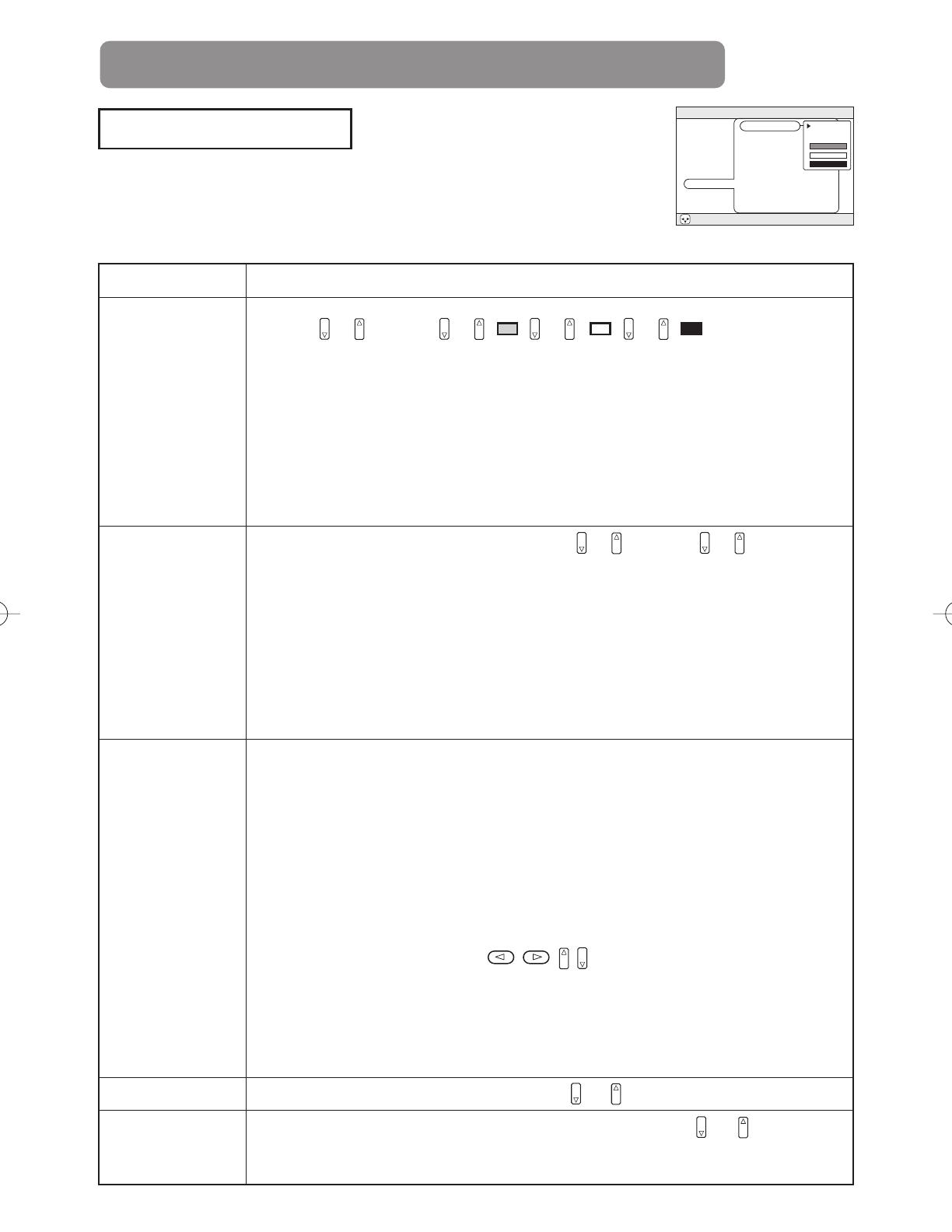
Example : SCREEN Menu
(BLANK)
MENU
: SELECT
MAIN
PICTURE-1
PICTURE-2
INPUT
AUTO
SCREEN
OPTION
WIRELESS
BLANK
START UP
MyScreen
MyScreen Size
MyScreen Lock
MyScreen
ORIGINAL
7
OPTION Menu
With the OPTION menu, the five items shown in the Table below can
be performed.
Please perform each operation in accordance with the instructions in
the Table.
WIRELESS Menu
The WIRELESS menu is only enabled if the wireless function is enabled. Using the
wireless function requires a Wireless & Network Module Terminal (sold separately). See
the Wireless & Network Module Terminal users manual for more information about the
WIRELESS menu. Contact your local dealer for more information about the wireless
function and Wireless & Network Module Terminal.
MENU
: SELECT
MAIN
PICTURE-1
PICTURE-2
INPUT
AUTO
SCREEN
OPTION
WIRELESS
VOLUME
WHISPER
IR REMOTE
LAMP TIME
FILTER TIME
12
Item Description
VOLUME
Adjust Volume: High Low
IR REMOTE
Selecting the remote control receiver:
The unit has 3 remote control receivers, as shown in the figure
to the right (1, 2, and 3). You can select which of them to
activate (“v” in the figure), and which to disable.
The ambient lighting and other factors may prevent the
remote control operation from functioning properly. If this
happens, use this function to disable receivers being
impacted by unneeded light.
LAMP TIME
Refer to LAMP TIME: When set, this function displays the total time the
projector lamp has been used since new.
Reset LAMP TIME [Use this function only when the lamp has been replaced!]:
Depress the RESET button for at least 3 seconds while lamp time is being
displayed. The reset menu will then appear. After you replace the lamp with a
new lamp, select RESET on the menu with the button.
Do not reset the lamp time unless you have replaced the lamp. And, always
reset the lamp time when replacing the lamp.
Before replacing the lamp, carefully read the descriptions headed "THE LAMP".
FILTER TIME
Refer to FILTER TIME: This function displays the total time the air-filter has
been used since new.
Reset FILTER TIME [Use this function only when the filter is cleaned or replaced!]:
Depress the RESET button for at least 3 seconds while lamp time is being
displayed. The reset menu will then appear. After you replace the filter, select
RESET on the menu with the button.
RESET CANCEL
• Do not reset the filter time unless you have cleaned or replaced the filter. And,
always reset the filter time when cleaning or replacing the filter. The message
functions will not operate properly if the filter time is not reset correctly.
Before cleaning or replacing the filter, carefully read the descriptions headed "THE AIR FILTER".
Example : OPTION Menu
(VOLUME)
OPTION Menu
1
1
2
2
3
12 3
12 3
12 3
12 3
12 3
12 3
3
8
WHAT TO DO WHEN YOU THINK A MACHINE DEFECT HAS OCCURRED
Related Messages
When the unit's power is ON, messages such as those shown below may be displayed. When
any such message is displayed on the screen, please respond as described below.
Message Description
CLEAN THE AIR FILTER
AFTER CLEANING AIR FILTER,
RESET THE FILTER TIMER.
A note of precaution when cleaning the air filter.
After cleaning the filter, operate FILTER TIME of the OPTION
Menu ( ), and perform reset of the filter timer.
NO INPUT IS DETECTED
ON
There is no input signal.
Please confirm the signal input connection, and the status of the
signal source.
SYNC IS OUT OF RANGE
ON
kHz Hz
The horizontal or vertical wavelength of the inputted signal is
outside of the response parameters of this unit. Please confirm
the specs for this unit or the signal source specs.
CHECK THE AIR FLOW
The internal portion temperature is rising. Please turn the power
OFF, and allow the unit to cool down for approximately 20
minutes. After having confirmed the following items, then please
resent the power to ON.
Is there blockage of the air passage aperture?
Is the air filter dirty?
Does the peripheral temperature exceed 35°C?
fH fV
7
9
Regarding the Indicator Lamps
Lighting and flashing of the POWER indicator, the LAMP indicator, and the
TEMP indicator have the meanings as described in the Table below.
Please respond in accordance with the instructions within the Table.
POWER
indicator
LAMP
indicator
TEMP
indicator
Description
The orange
lamp is lighted
Turned OFF
(Not lighted)
Turned OFF
(Not lighted)
The STANDBY mode is set
Flashing of the green lamp
Turned OFF Turned OFF
The unit is warming up. Please wait.
The green lamp is lighted
Turned OFF Turned OFF
The unit is in an ON state. Ordinary operations may be performed.
Flashing of the orange lamp
Turned OFF Turned OFF
The unit is cooling down. Please wait.
Blinking of the
red lamp
- -
The unit is cooling down. Please wait.
A certain error has been detected. Wait until the POWER indicator lamp has finished
flashing, and then perform the proper response measure using the item descriptions
below as reference.
The red lamp
is lighted, or
blinks
The red lamp
is lighted
Turned
OFF
The lamp does not light.
There is a possibility that the interior portion has become heated. Turn the power OFF and wait
approximately 20 minutes. After the main unit has cooled down, please confirm whether or not
there is blockage of the air passage aperture, whether or not the filter is dirty, and/or whether or
not the peripheral temperature exceeds 35°C, etc. After performing any needed maintenance,
turn the power ON again; if the same display is displayed, then please change the lamp.
The red lamp
is lighted, or
blinks
Blinking of the
red lamp
Turned
OFF
Either there is no lamp and/or lamp cover, or either of these has not been properly fixed
(attached). Turn the power OFF and wait approximately 45 minutes. After the main unit has
sufficiently cooled down, please make confirmation of the attachment state of the lamp and
lamp cover. After performing any needed maintenance, turn the power ON again; if the same
display is displayed, then please contact a sales store or a service company.
The red lamp
is lighted, or
blinks
Turned
OFF
Blinking of the
red lamp
The cooling fan is not operating. Turn the power OFF and wait approximately 20 minutes. After the
main unit has cooled down, please make confirmation that no foreign matter has become caught in
the fan, etc. After performing any needed maintenance, turn the power ON again; if the same display
is displayed, then please contact a sales store or a service company.
The red lamp is
lighted, or
blinks
Turned
OFF
The red lamp is
lighted
There is a possibility that the interior portion has become heated. Turn the power OFF and wait
approximately 20 minutes. After the main unit has cooled down, please confirm whether or not
there is blockage of the air passage aperture, whether or not the filter is dirty, and/or whether or
not the peripheral temperature exceeds 35°C, etc. After performing any needed maintenance,
turn the power ON again; if the same display is displayed, then please contact a sales store or a
service company.
The green lamp
is lighted
Alternative blinking
with the red lamp
There is a possibility that the interior portion has become overcooled. Please use the unit within
the usage temperature parameters (0°C to 35°C). After performing any needed maintenance,
turn the power ON again; if the same display is displayed, then please contact a sales store or a
service company.
The green
lamp is lighted
Simultaneous blinking
with the red lamp
This is a notification that it is time to clean the filter.
After cleaning the filter, operate the FILTER TIME portion of the OPTION Menu, and perform
reset of the FILTER TIME.
When the interior portion has become overheated, for safety purposes, the power source is automatically turned OFF,
and the indicator lamps may also be turned OFF. Press the “ ” (power OFF) side of the main power switch, and wait
for approximately 20 minutes. Please then use the unit only after having first confirmed that the unit has sufficiently
cooled down.
NOTE
9
10
WHAT TO DO WHEN YOU THINK A MACHINE DEFECT HAS OCCURRED (continued)
Phenomena That May Easily Be Mistaken for Machine Defects
Before requesting repair, check in accordance with the following chart.
If the situation cannot be corrected, then contact your dealer.
Although bright spots or dark spots may appear on the screen, this is a unique characteristic of liquid crystal displays, and
such do not constitute or imply a machine defect.
NOTE
Phenomenon
Cases not involving a machine defect
Items to be confirmed
Reference
Page(s)
Power does not
come ON
The main power source is not ON.
Turn on the main power.
Vol.1-3, 15
The electrical power cord is not plugged in. Correctly connect the power cord.
The main power source has been
interrupted during operation, such as by
a power outage (blackout), etc.
Be sure to press the “
O
” (power OFF) side
of the main power switch, and leave this OFF
for approximately 20 minutes. After the unit
has sufficiently cooled down, turn ON the
power source.
Vol.1-15
No sound or
pictures are
outputted
The input changeover settings
are mismatched.
Select the input signal, and
correct the settings.
Vol.1-16
No signal is being inputted.
Correctly connect the connection cord.
Vol.1-8-12
Pictures are
displayed, but no
sounds are heard
The electrical wiring to this unit
is not correctly connected.
Correctly connect the connection cord.
Vol.1-8-12
The volume setting has been set at (or
adjusted to) an extremely low level.
Adjust the VOLUME setting to a higher level.
Vol.1-18
The MUTE mode is the current setting.
Press the MUTE button to release
(change) the MUTE mode setting.
Vol.1-18
Sounds are
heard, but no
pictures are
displayed
The electrical wiring to this unit
is not correctly connected.
Correctly connect the connection cord.
Vol.1-8-12
The brightness setting has been set at
(or adjusted to) an extremely low level.
Adjust the BRIGHT setting to a
brighter level.
Vol.2-2
The lens cap has not been removed.
Remove the lens cap.
Vol.1-15
Colors have a faded-
out appearance
Color tone is poor
Color depth setting or color tone setting
Perform picture adjustments by changing the
COLOR BAL R, the COLOR BAL B, and/or the
TINT settings, etc.
Vol.2-3
Pictures appear
dark
The brightness setting and/or contrast
setting has not been properly adjusted.
Perform picture adjustments by changing the
BRIGHT and/or CONTRAST settings, etc.
Vol.2-2
Lamp is approaching the end of its
product lifetime.
Exchange the old lamp with a new
lamp.
Vol.1-27, 28
Pictures appear
blurry
Either the FOCUS setting or the H
PHASE is not properly adjusted.
Adjust the FOCUS and H PHASE settings.
Vol.1-16
Vol.2-3
Input signal changes
with no-operation.
INPUT dial is set between the click
points.
Turn the INPUT dial and set it at the
click point.
Vol.1-16
Dimension Diagram
Unit : mm
This specifications are subject to change without notice.
NOTE
SPECIFICATIONS
11
Item Specification
Product name Liquid crystal projector
Liquid
crystal
panel
Panel size 3.3 cm (1.3 type)
Drive system TFT active matrix
Pixels 786,432 pixels (1024 horizontal x 768 vertical)
Lens Zoom lens F=1.7 ~ 2.3 f=49 ~ 64 mm
Lamp 150 W UHB
Speaker 1.0W
+
1.0W (Stereo)
Power supply AC100 ~ 120V, 3.0A / AC220 ~ 240V, 1.4A
Power consumption 270W
Temperature range 0 ~ 35°C (Operating)
Size 380 (W) x 120 (H) x 290 (D) mm (Not including protruding parts)
Weight (mass) 6.0 kg
Ports
Optional Parts
Lamp: DT00571 Air Filter: NJ07081
* For others, consult your dealer.
RGB Input Ports
RGB ................................1
BNC (when RGB selected)
– (R.G.B.H.V) ..................1
DVI..................................1
VIDEO Input Ports
VIDEO IN ........................1
S-VIDEO IN ....................1
COMPONENT VIDEO
– (CR/PR, CB/PB, Y) ........1
BNC
(when COMPONENT selected)
– (CR/PR, Y, CB/PB) ........1
AUDIO Ports
AUDIO IN 1 ....................1
AUDIO IN 2 ....................1
AUDIO IN (R, L)..............1
RGB Output Port
RGB OUT........................1
AUDIO Output Port
AUDIO OUT....................1
CONTROL Ports
CONTROL ......................1
USB ................................1
Other Ports
WIRELESS & NETWORK MODULE
....1
REMOTE CONTROL ......1
12
If a problem occurs with the equipment, first refer to the WHAT TO DO WHEN YOU
THINK A MACHINE DEFECT HAS OCCURRED section and run through the suggested
checks. If this does not resolve the problem contact your dealer or service company. They
will tell you what warranty condition is applied.
WARRANTY AND AFTER-SERVICE
8
1
TECHNICAL
TECHNICAL
SIGNAL CONNECTOR PIN ASSIGNMENT
RGB
RGB OUT
D-sub 15-pin Shrink Mini Din 4-pin
S-VIDEO
Mini Din 4-pin
Pin No
Signal
1
Color:
0.286Vp-p (NTSC, burst signal),
75 terminator
0.3Vp-p (PAL/SECAM, burst signal),
75 terminator
2
Brightness:
1.0Vp-p, 75 terminator
3 Ground
4 Ground
signal Terminal Specification
RGB signal
input
RGB
Video: RGB separate, Analog, 0.7Vp-p, 75 terminator (positive)
H/V. sync.: TTL level (positive/negative)
Composite sync.: TTL level
D-sub 15-pin shrink jack
BNC (RGB)
(R,G,B,H,V)
Video: RGB separate, Analog 0.7Vp-p, 75 terminator (positive)
H/V. sync.: TTL level (positive/negative)
Composite sync.: TTL level
BNC connector x 5
DVI
TMDS, DC 150-1200 mV/AC 1.56 Vp-p, TTL Level (Positive/Negative)
DVI connector
AUDIO IN 1
200mVrms, 57 k (max. 3.0Vp-p)
Stereo mini jack
AUDIO IN 2
Video signal
input
VIDEO IN 1.0Vp-p, 75 terminator, RCA jack
S-VIDEO IN
Brightness signal: 1.0Vp-p, 75 terminator
Color signal: 0.286Vp-p (NTSC, burst signal),75 terminator
Color signal: 0.300Vp-p (PAL/SECAM, burst signal),75 terminator
Mini DIN 4-pin jack
COMPONENT VIDEO
(CR/PR, CB/PB, Y)
Y signal: 1.0 Vp-p, 75 terminator
C
R/PR signal: 0.7 Vp-p, 75 terminator
C
B/PB signal: 0.7 Vp-p, 75 terminator
RCA jack x 3 (BNC connector x 5)
BNC (COMPONENT)
(C
R/PR, CB/PB, Y)
AUDIO IN R L
200mVrms, 57 k (max. 3.0Vp-p)
RCA jack
Signal output
RGB OUT
Video: RGB separate, Analog 0.7Vp-p, 75 (positive)
Sync.: H,V separate, TTL level (positive/negative)
Composite sync.: TTL level
D-sub 15-pin shrink jack
AUDIO OUT
0~200mV(rms), output impedance 1k (max. 3.0Vp-p)
Stereo mini jack
Control
functions
CONTROL D-sub 15pin shrink plug
USB USB jack (B type)
Pin No Signal Pin No Signal
1 Video input Red 9 -
2 Video input Green 10 Ground
3 Video input Blue 11 -
4 -
12
RGB IN: SDA (DDC)
6 Ground Red RGB OUT : -
7 Ground Green 13
H. sync./ Composite sync.
8 Ground Blue 14 Vertical sync
15
RGB IN : SCL (DDC)
RGB OUT : -
2
EXAMPLE OF COMPUTER SIGNAL
Some computers may have multiple display screen modes. Use of some
of these modes will not be possible with this projector.
• Be sure to check jack type, signal level, timing and resolution before connecting this
projector to a computer.
• Depending on the input signal, full-size display may not be possible in some cases.
Refer to the number of display pixels above.
• Although the projector can display signals (except DVI input) with resolution up to
UXGA (1,600 x 1,200), the signal will be converted to the projector’s panel resolution
before being displayed. The best display performance will be achieved if the
resolutions of the input signal and projector panel are identical.
• The image may not be displayed correctly when the input sync. signal is “Composite
Sync.” or “Sync. on G”.
• UXGA (1,600 x 1,200) signals cannot be displayed with DVI input.
NOTE
Resolution
H
××
V
fH (kHz) fV (Hz) Rating Signal mode
Display
mode
720 × 400
37.9 85.0 VESA TEXT Zoom in
640 × 480
31.5 59.9 VESA VGA (60Hz) Zoom in
640 × 480
35.0 66.7 Mac13"mode Zoom in
640 × 480
37.9 72.8 VESA VGA (72Hz) Zoom in
640 × 480
37.5 75.0 VESA VGA (75Hz) Zoom in
640 × 480
43.3 85.0 VESA VGA (85Hz) Zoom in
800 × 600
35.2 56.3 VESA SVGA (56Hz) Zoom in
800 × 600
37.9 60.3 VESA SVGA (60Hz) Zoom in
800 × 600
48.1 72.2 VESA SVGA (72Hz) Zoom in
800 × 600
46.9 75.0 VESA SVGA (75Hz) Zoom in
800 × 600
53.7 85.1 VESA SVGA (85Hz) Zoom in
832 × 624
49.7 74.5 Mac16"mode Zoom in
1024 × 768
48.4 60.0 VESA XGA (60Hz)
1024 × 768
56.5 70.1 VESA XGA (70Hz)
1024 × 768
60.0 75.0 VESA XGA (75Hz)
1024 × 768
68.7 85.0 VESA XGA (85Hz)
1152 × 864
67.5 75.0 VESA SXGA (75Hz) Zoom out
1280 × 960
60.0 60.0 VESA SXGA (60Hz) Zoom out
1280 × 1024
64.0 60.0 VESA SXGA (60Hz) Zoom out
1280 × 1024
80.0 75.0 VESA SXGA (75Hz) Zoom out
1280 × 1024
91.2 85.0 VESA SXGA (85Hz) Zoom out
1600 × 1200
75.0 60.0 VESA UXGA (60Hz) Zoom out
3
The following signals are used for the initial settings.
The signal timing of some computer models may be different. In such case, refer to
adjust the V.POSIT and H.POSIT of the menu.
Display interval c
Back porch b
Sync a
Front porch d
Display interval c
Back porch b
Sync a
Front porch d
Computer /
Signal
Horizontal signal timing (µs)
a b c d
TEXT 2.0 3.0 20.3 1.0
VGA (60Hz) 3.8 1.6 25.4 0.6
Mac 13"mode 2.1 3.2 21.2 2.1
VGA (72Hz) 1.3 3.8 20.3 0.5
VGA (75Hz) 2.0 3.8 20.3 0.5
VGA (85Hz) 1.6 2.2 17.8 1.6
SVGA (56Hz) 2.0 3.6 22.2 0.7
SVGA (60Hz) 3.2 2.2 20.0 1.0
SVGA (72Hz) 2.4 1.3 16.0 1.1
SVGA (75Hz) 1.6 3.2 16.2 0.3
SVGA (85Hz) 1.1 2.7 14.2 0.6
Mac 16"mode 1.1 3.9 14.5 0.6
XGA (60Hz) 2.1 2.5 15.8 0.4
XGA (70Hz) 1.8 1.9 13.7 0.3
XGA (75Hz) 1.2 2.2 13.0 0.2
XGA (85Hz) 1.0 2.2 10.8 0.5
1152×864 (75Hz)
1.2 2.4 10.7 0.6
1280×960 (60Hz)
1.0 2.9 11.9 0.9
1280×1024 (60Hz)
1.0 2.3 11.9 0.4
1280×1024 (75Hz)
1.1 1.8 9.5 0.1
1280×1024 (85Hz)
1.0 1.4 8.1 0.4
1600×1200 (60Hz)
1.2 1.9 9.9 0.4
Computer /
Signal
Vertical signal timimg (lines)
a b c d
TEXT 3 42 400 1
VGA (60Hz) 2 25 480 2
Mac 13"mode 3 39 480 3
VGA (72Hz) 3 20 480 1
VGA (75Hz) 3 16 480 1
VGA (85Hz) 3 25 480 1
SVGA (56Hz) 2 22 600 1
SVGA (60Hz) 4 23 600 1
SVGA (72Hz) 6 23 600 37
SVGA (75Hz) 3 21 600 1
SVGA (85Hz) 3 27 600 1
Mac 16"mode 3 39 624 1
XGA (60Hz) 6 29 768 3
XGA (70Hz) 6 29 768 3
XGA (75Hz) 3 28 768 1
XGA (85Hz) 3 36 768 1
1152×864 (75Hz)
3 32 864 1
1280×960 (60Hz)
3 36 960 1
1280×1024 (60Hz)
3 38 1024 1
1280×1024 (75Hz)
3 38 1024 1
1280×1024 (85Hz)
3 44 1024 1
1600×1200 (60Hz)
3 46 1200 1
INITIAL SET SIGNALS
4
CONNECTION TO THE MOUSE CONTROL
1
2
3
4
1
2
3
4
+
5V
DATA
+
DATA
GND
+
5V
DATA
+
DATA
GND
1
234
2
1
3
4
USB jack
(B type)
USB jack
(A type)
Projector
USB cable
Computer
ADB Mouse
2
1
4
3
6
5
2
1
4
3
8
7
10
9
12
11
14
13
15
RTS
GND
+5V
ADB
GND
+5V
(
POWER ON
)
DATA
2
1
4
3
Mouse jack
Mini DIN 4-pin
Projector
Computer
CONTROL Terminal
D-sub 15-pin shrink jack
Serial Mouse
2
1
4
3
6
5
2
1
4
3
6
5
8
7
10
9
8
7
9
12
11
14
13
15
RI
CD
RD
TD
DTR
GND
DSR
CTS
RTS
RTS
GND
SEL0
TD
21
4
3
6
5
8
9
7
Mouse jack
D-sub 9-pin
Projector
Computer
CONTROL Terminal
D-sub 15-pin shrink jack
USB Mouse
PS/2 Mouse
2
1
4
3
6
5
2
1
4
3
6
5
8
7
10
9
12
11
14
13
15
CLK
DATA
SEL0
RTS
GND
+5V
DATA
GND
+5V
CLK
2
1
4
3
6
5
Mouse jack
Mini DIN 6-pin
Projector
Computer
CONTROL Terminal
D-sub 15-pin shrink jack
5
(1)
Turn off the projector and computer power supplies, and connect with the RS-232C
adapter via the RS-232C cable.
(2) Turn on the computer power supply and after the computer has started up, turn on the
projector power supply.
Control jack
D-sub 15-pin shrink jack
1
2
3
4
5
6
7
8
9
10
11
12
13
14
15
RD
TD
GND
SELO
RTS
1
2
3
4
5
6
7
8
9
CD
RD
TD
DTR
GND
DSR
RTS
DTS
RI
1
2345
67
8
9
RS-232C jack
D-sub 9-pin
Projector Computer
Communications setting
19200bps, 8N1
1 Protocol
Consist of header (7 bytes) + command data (6 bytes).
2 Header
BE + EF + 03 + 06 + 00 + CRC_low + CRC_high
CRC_low : Lower byte of CRC flag for command data.
CRC_high : Upper byte of CRC flag for command data.
3 Command data
byte_0 byte_1 byte_2 byte_3 byte_4 byte_5
Action Type Setting code
low high low high low high
Command data chart
Action (byte_0 - 1)
Action Classification Content
1 SET Change setting to desired value.
2 GET Read projector internal setup value.
4 INCREMENT Increment setup value by 1.
5 DECREMENT Decrement setup value by 1.
6 EXECUTE Run a command.
RS-232C COMMUNICATION
RS-232C adapter
6
Requesting projector status (Get command)
(1) Send the request code Header + Command data (‘02H’+‘00H’+ type (2 bytes)
+‘00H’+‘00H’) from the computer to the projector.
(2) The projector returns the response code ‘1DH’+ data (2 bytes) to the computer.
Changing the projector settings (Set command)
(1) Send the setting code Header + Command data (‘01H’+‘00H’+ type (2 bytes) +
setting code (2 bytes)) from the computer to the projector.
(2) The projector changes the setting based on the above setting code.
(3) The projector returns the response code ‘06H’ to the computer.
Using the projector default settings (Reset Command)
(1) The computer sends the default setting code Header + Command data (‘06H’+‘00H’+
type (2 bytes) +‘00H’+‘00H’) to the projector.
(2) The projector changes the specified setting to the default value.
(3) The projector returns the response code ‘06H’ to the computer.
Increasing the projector setting value (Increment command)
(1) The computer sends the increment code Header + Command data (‘04H’+‘00H’+
type (2 bytes) +‘00H’+‘00H’) to the projector.
(2) The projector in creases the setting value on the above setting code.
(3) The projector returns the response code ‘06H’ to the computer.
Decreasing the projector setting value (Decrement command)
(1) The computer sends the decrement code Header + Command data (‘05H’+‘00H’+
type (2 bytes) +‘00H’ + ‘00H’) to the projector.
(2) The projector decreases the setting value on the above setting code.
(3) The projector returns the response code ‘06H’ to the computer.
When a command sent by the projector cannot be understood by the computer
When the command sent by the projector cannot be understood, the error command ‘15H’ is
returned by the computer. Some times, the projector ignores RS-232C commands during
other works. If the error command ‘15H’ is returned, please send the same command again.
When data sent by the projector cannot be practice
When the command sent by the projector cannot be practiced, the the error code ‘1cH’
+‘xxxxH’ is returned.
When the data length is greater than indicated by the data length code, the projector will
ignore the excess data code.
Conversely, when the data length is shorter than indicated by the data length code, an
error code will be returned to the projector.
RS-232C COMMUNICATION (continued)
Operation cannot be guaranteed when the projector receives an
undefined command or data.
Provide an interval of at least 40ms between the response code and any other code.
• The projector outputs test data when the power supply is switched ON, and when the
lamp is lit. Ignore this data.
• Commands are not accepted during warm-up.
NOTE
7
Command data chart
Names Operation type Header
Command data
CRC Action Type Setting code
Blank Color
Set
Blue BE EF 03 06 00 CB D3 01 00 00 30 03 00
White BE EF 03 06 00 6B D0 01 00 00 30 05 00
Black BE EF 03 06 00 9B D0 01 00 00 30 06 00
MyScreen BE EF 03 06 00 FB CA 01 00 00 30 20 00
ORIGNAL BE EF 03 06 00 FB E2 01 00 00 30 40 00
Get BE EF 03 06 00 08 D3 02 00 00 30 00 00
Mirror
Set
Normal BE EF 03 06 00 C7 D2 01 00 01 30 00 00
H Inverse BE EF 03 06 00 57 D3 01 00 01 30 01 00
V lnverse BE EF 03 06 00 A7 D3 01 00 01 30 02 00
H&V Inverse BE EF 03 06 00 37 D2 01 00 01 30 03 00
Get BE EF 03 06 00 F4 D2 02 00 01 30 00 00
Freeze
Set
Normal BE EF 03 06 00 83 D2 01 00 02 30 00 00
Freeze BE EF 03 06 00 13 D3 01 00 02 30 01 00
Get BE EF 03 06 00 B0 D2 02 00 02 30 00 00
Startup
Set
ORIGNAL BE EF 03 06 00 0B D2 01 00 04 30 00 00
OFF BE EF 03 06 00 9B D3 01 00 04 30 01 00
MyScreen BE EF 03 06 00 CB CB 01 00 04 30 20 00
Get BE EF 03 06 00 38 D2 02 00 04 30 00 00
Language
Set
English BE EF 03 06 00 F7 D3 01 00 05 30 00 00
Français BE EF 03 06 00 67 D2 01 00 05 30 01 00
Deutsch BE EF 03 06 00 97 D2 01 00 05 30 02 00
Español BE EF 03 06 00 07 D3 01 00 05 30 03 00
Italiano BE EF 03 06 00 37 D1 01 00 05 30 04 00
Norsk BE EF 03 06 00 A7 D0 01 00 05 30 05 00
Nederlands BE EF 03 06 00 57 D0 01 00 05 30 06 00
Português BE EF 03 06 00 C7 D1 01 00 05 30 07 00
BE EF 03 06 00 37 D4 01 00 05 30 08 00
BE EF 03 06 00 A7 D5 01 00 05 30 09 00
BE EF 03 06 00 57 D5 01 00 05 30 0A 00
Get BE EF 03 06 00 C4 D3 02 00 05 30 00 00
Magnify
Get BE EF 03 06 00 7C D2 02 00 07 30 00 00
Increment BE EF 03 06 00 1A D2 04 00 07 30 00 00
Decrement BE EF 03 06 00 CB D3 05 00 07 30 00 00
Auto off
Get BE EF 03 06 00 08 86 02 00 10 31 00 00
Increment BE EF 03 06 00 6E 86 04 00 10 31 00 00
Decrement BE EF 03 06 00 BF 87 05 00 10 31 00 00
Brightness Reset
Execute BE EF 03 06 00 58 D3 06 00 00 70 00 00
Contrast Reset Execute BE EF 03 06 00 A4 D2 06 00 01 70 00 00
V.Position Reset
Execute BE EF 03 06 00 E0 D2 06 00 02 70 00 00
8
Command data chart
(continued)
Names Operation type Header
Command data
CRC Action Type Setting code
H.Position Reset Execute BE EF 03 06 00 IC D3 06 00 03 70 00 00
H.Size Reset Execute BE EF 03 06 00 68 D2 06 00 04 70 00 00
Color Balance
R Reset
Execute BE EF 03 06 00 94 D3 06 00 05 70 00 00
Color Balance
B Reset
Execute BE EF 03 06 00 D0 D3 06 00 06 70 00 00
Sharpness Reset Execute BE EF 03 06 00 C4 D0 06 00 09 70 00 00
Color Reset Execute BE EF 03 06 00 80 D0 06 00 0A 70 00 00
Tint Reset Execute BE EF 03 06 00 7C D1 06 00 0B 70 00 00
Keystone_V Reset Execute BE EF 03 06 00 08 D0 06 00 0C 70 00 00
Keystone_H Reset Execute BE EF 03 06 00 98 D8 06 00 20 70 00 00
Auto Adjust Execute BE EF 03 06 00 91 D0 06 00 0A 20 00 00
Auto Keystone_V
Execute BE EF 03 06 00 E5 D1 06 00 0D 20 00 00
Lamp Time Reset Execute BE EF 03 06 00 58 DC 06 00 30 70 00 00
Filter Time Reset Execute BE EF 03 06 00 98 C6 06 00 40 70 00 00
Blank on/off
Set
off BE EF 03 06 00 FB D8 01 00 20 30 00 00
on BE EF 03 06 00 6B D9 01 00 20 30 01 00
Get BE EF 03 06 00 C8 D8 02 00 20 30 00 00
Error Status Get
BE EF 03 06 00 D9 D8 02 00 20 60 00 00
(Example of Return)
00 00 01 00 02 00 03 00
(Normal) (Cover-error) (Fan-error) (Lamp-error)
04 00 05 00 06 00 07 00 08 00
(Temp-error) (Air flow-error) (Lamp-Time-over) (Cool-error) (Filter-Error)
Power
Set
OFF
BE EF 03 06 00 2A D3 01 00 00 60 00 00
ON
BE EF 03 06 00 BA D2 01 00 00 60 01 00
Get
BE EF 03 06 00 19 D3 02 00 00 60 00 00
Input Source
Set
RGB BE EF 03 06 00 FE D2 01 00 00 20 00 00
BNC (RGB) BE EF 03 06 00 3E D0 01 00 00 20 04 00
Video BE EF 03 06 00 6E D3 01 00 00 20 01 00
S-Video BE EF 03 06 00 9E D3 01 00 00 20 02 00
Component
BE EF 03 06 00 AE D1 01 00 00 20 05 00
DVI BE EF 03 06 00 0E D2 01 00 00 20 03 00
BNC (Component)
BE EF 03 06 00 5E D1 01 00 00 20 06 00
Get BE EF 03 06 00 CD D2 02 00 00 20 00 00
Volume
Get BE EF 03 06 00 31 D3 02 00 01 20 00 00
Increment BE EF 03 06 00 57 D3 04 00 01 20 00 00
Decrement BE EF 03 06 00 86 D2 05 00 01 20 00 00
Mute
Set
Normal BE EF 03 06 00 46 D3 01 00 02 20 00 00
Mute BE EF 03 06 00 D6 D2 01 00 02 20 01 00
Get BE EF 03 06 00 75 D3 02 00 02 20 00 00
Brightness
Get BE EF 03 06 00 89 D2 02 00 03 20 00 00
Increment BE EF 03 06 00 EF D2 04 00 03 20 00 00
Decrement BE EF 03 06 00 3E D3 05 00 03 20 00 00
Contrast
Get BE EF 03 06 00 FD D3 02 00 04 20 00 00
Increment BE EF 03 06 00 9B D3 04 00 04 20 00 00
Decrement BE EF 03 06 00 4A D2 05 00 04 20 00 00
Color Balance R
Get BE EF 03 06 00 01 D2 02 00 05 20 00 00
Increment BE EF 03 06 00 67 D2 04 00 05 20 00 00
Decrement BE EF 03 06 00 B6 D3 05 00 05 20 00 00
  • Page 1 1
  • Page 2 2
  • Page 3 3
  • Page 4 4
  • Page 5 5
  • Page 6 6
  • Page 7 7
  • Page 8 8
  • Page 9 9
  • Page 10 10
  • Page 11 11
  • Page 12 12
  • Page 13 13
  • Page 14 14
  • Page 15 15
  • Page 16 16
  • Page 17 17
  • Page 18 18
  • Page 19 19
  • Page 20 20
  • Page 21 21
  • Page 22 22
  • Page 23 23

Hitachi CP-X870 User manual

Category
Data projectors
Type
User manual

Ask a question and I''ll find the answer in the document

Finding information in a document is now easier with AI