Page is loading ...

User Guide
Guide de l’utilisateur
Bedlenungsanleltung
Guía del usuario
Guida Dell’utente
Användarhandbok
Käyttöopas
使用者指南
使用者指南
PJ751
Image Size 31” – 300”
LCD Projector
Руководство пользователя

ViewSonic PJ751 i
Contents
For Your Records ...........................................................................1
FEATURES
BEFORE USE
Package Contents ..........................................................................3
Component Names .........................................................................4
Inserting the Batteries .....................................................................6
Attaching the Strap Handle .............................................................6
INSTALLATION
Installation of the Projector and Screen...........................................7
Angle Adjustment ............................................................................7
Ports and Cables ............................................................................8
Power Connection ..........................................................................9
Connecting Your Devices ...............................................................9
Plug & Play .....................................................................................9
OPERATION
Power ON .....................................................................................13
Power OFF ...................................................................................13
Selecting an Input Signal ..............................................................14
Adjusting Image Size and Focus ..................................................14
Adjusting the Volume ....................................................................15
Temporarily Muting the Sound ......................................................15
Adjusting the Image Position ........................................................16
Using the Automatic Adjustment Feature .....................................17
Correcting Keystroke Distortions ..................................................18
Using the Magnify Feature ............................................................19
Freezing the Screen .....................................................................19
Signal Searching ...........................................................................20
Selecting the Aspect Ratio ............................................................20
Temporarily Blanking the Screen ..................................................20
Using the Menu Functions ............................................................21
Operating the PC Screen ..............................................................22
OSD MENU FUNCTION DESCRIPTION
Main Menu ....................................................................................23
Picture 1 Menu ..............................................................................24
Picture 2 Menu ..............................................................................24
Input Menu ..............................................................................................25
Screen Menu ................................................................................26
Option Menu .................................................................................28

ViewSonic PJ751 ii
Contents
MAINTENANCE
Lamp .............................................................................................29
Lamp Life ......................................................................................29
Replacing the Lamp ......................................................................30
Caring for the Air Filter ..................................................................31
Caring for the Inside of the Projector ............................................32
Caring for the Lens .......................................................................32
Caring for the Cabinet and Remote Control Transmitter ..............32
TROUBLESHOOTING
On-Screen Messages ...................................................................33
Problem Diagnostics .....................................................................34
SPECIFICATIONS
Outline Dimensions .......................................................................35
Customer Support .........................................................................36
LIMITED WARRANTY
ViewSonic Projector ......................................................................37
Appendix
Power Cord Safety Guidelines ......................................................38
Compliance Information for U.S.A. ...............................................40
Compliance Information for Canada .............................................40
Compliance Information for European Countries ..........................40
User Information for All Countries .................................................40

ViewSonic PJ751
1
Copyright © ViewSonic Corporation, 2003. All rights reserved.
Apple, Mac and ADB registered trademarks of Apple Computer, Inc.
Microsoft, Windows, Windows NT, and the Windows logo are registered trademarks of Microsoft
Corporation in the United States and other countries.
ViewSonic, the three birds logo. airsync, and OnView are registered trademarks of ViewSonic Cor-
poration.
VESA and SVGA are registered trademarks of the Video Electronics Standards Association.
DPMS and DDC are trademarks of VESA.
PS/2, VGA and XGA are registered trademarks of International Business Machines Corporation.
As an ENERGY STAR
®
partner, ViewSonic Corporation has determined that this product meets the
ENERGY STAR
®
guidelines for energy efficiency.Disclaimer: ViewSonic Corporation shall not be lia-
ble for technical or editorial errors or omissions contained herein; nor for incidental or consequential
damages resulting from furnishing this material, or the performance or use of this product.
In the interest of continuing product improvement, ViewSonic Corporation reserves the right to
change product specifications without notice. Information in this document may change without
notice.
No part of this document may be copied, reproduced, or transmitted by any means, for any purpose
without prior written permission from ViewSonic Corporation.
To meet your future needs, and to receive any additional product infor-
mation as it becomes available, please register your projector's war-
ranty on the Internet at:
http://www.viewsonic.com
For Your Records
Product Name:
Model Number:
Document Number
ViewSonic PJ751
VPROJ27104-1W
A-CD-PJ751
___________________________
___________________________
Serial Number:
Purchase Date:

2
ViewSonic PJ751
FEATURES
1 High brightness for clear images in any settings
2 Whisper mode for quiet operation and extended lamp life
3 Magnification feature allows selected parts of the screen to be magnified for closer viewing
4 “My Screen” feature creates a customized start-up screen

ViewSonic PJ751
3
BEFORE USE
Package Contents
Make sure all of the following items are included in the package. If anything is missing, please con-
tact ViewSonic Corp.
NOTE: Keep the original packing material for future shipment.
NOTE:
Applicable power cord is shipped with the projector to the point of destination.
WARNING: Before using this equipment, read this manual thoroughly. Always ensure that the
equipment is used safely.
Power Cord
(US)
Power Cord
(UK)
Power Cord
(EURO)
Batteries for
Remote Control
Quick Start Guide
RGB Cable Component
Video Cable
Mouse cable
(PS/2)
Handle
Projector
Remote Control
Carrying Case
CD-Wizard
Power Cord
(China)
Video/Audio
Cable

4
ViewSonic PJ751
Component Names
Projector
Zoom Knob
Focus Ring
Remote Control Sensor
Lens
Lens Cap
INPUT Button
LAMP Indicator
TEMP Indicator
POWER Indicator
RESET Button
MENU Button
Ventilation Openings
(Exhaust)
Terminal Panel
(Refer below)
Remote Control Sensor
RGB IN 1 Terminal
RGB IN 2 Terminal
CONTROL Terminal
RGB OUT Terminal
USB Terminal
Foot Adjuster
FRONT/LEFT VIEW OF THE
PROJECTOR
REAR/RIGHT VIEW OF THE
PROJECTOR
TERMINAL PANEL
Speaker
Handle Hook
Power Switch
AC Inlet
(to the Power Cord)
Ventilation Openings
(Intake)
STANDBY/ON Button
COMPONENT VIDEO
Y Terminal
KEYSTONE Button
Foot Adjuster Button
Filter Cover
(Air Filter and Intake for
the Cooling Fan)
Rear Foot Adjuster
S-VIDEO Terminal
C
B
/P
B
Terminal
C
R
/P
R
Terminal
VIDEO IN Terminal
AUDIO IN R Terminal
AUDIO IN L Terminal
AUDIO IN 1 Terminal
AUDIO IN 2 Terminal
AUDIO OUT Terminal

ViewSonic PJ751
5
Remote Control
These functions work when the function for controlling the mouse has been activated. The mouse-
controlling function will be disabled if POSITION, BLANK ON and MENU ON are selected.
NOTE:
• Always keep the remote control device out of reach of children and pets.
• Be sure to protect the remote control device against any physical impact and dropping.
• Do not place any heavy object on top of the remote control device.
• Be sure to protect the remote control device against humidity or contact with wet surfaces.
• Do not leave the remote control device near the projector’s cooling fan outlet.
• Do not attempt to disassemble the remote control device.
VIDEO Button
STANDBY/ON Button
Disk pad
Used to operate the
mouse shift function and
left-click function.
AUTO Button
MENU Button
Used to click the left
mouse button.
Used to click the right
mouse button.
Used to click the right
mouse button.
MENU SELECT Button
Button
Used to operate the
mouse shift function.
POSITION Button
MAGNIFY Button
BLANK Button
LASER Button
RGB Button
MOUSE/RIGHT Button
KEYSTONE Button
RESET Button
REMOTE CONTROL DEVICE
FREEZE Button
MUTE Button
VOLUME Button
WAR NI NG
Th
e
l
aser po
i
nter o
f
t
h
e remote contro
l
d
ev
i
ce
i
s use
d
i
nstea
d
o
f
a
fi
nger or ro
d
.
Be sure to never look directly into the laser beam outlet or point the laser beam at other per-
sons. The laser beam may cause serious eye injuries.

6
ViewSonic PJ751
Inserting the Batteries
Insert the AA batteries into the remote control device.
1 Remove the battery cover. Push the knob while lift-
ing the battery compartment cover.
2 Insert the batteries according to their plus and
minus poles.
3 Replace the battery compartment cover.
CAUTION
• Be sure to only use the specified batteries with this
remote control device. Do not mix new and old
batteries, since this may result in a cracking or leakage of batteries posing a risk of fire or leading
to personal injury.
• Insert the batteries into the remote control device according to the indicated plus and minus poles.
An incorrect insertion may result in a cracking or leakage of batteries posing a risk of fire or lead-
ing to environmental pollution.
• Before disposing of the batteries, please be sure to observe the respective regulations concerning
the protection of environment in your country or area.
• Always be sure to keep the batteries out of reach of children or pets.
• If the remote control device will not be used for an extended period of time, remove the batteries
from its battery compartment.
NOTE:
Replace the batteries if the operation of the remote control device becomes irregular or weak.
Attaching the Strap Handle
Attach the enclosed handle, if necessary.
1 Lift up the hook and pass one end of the strap through the hole of the handle hook.
2 Buckle the end of the strap as shown on the right.
3 Fix the other end of the strap to the other handle hook in the same way.
CAUTION
Be sure that the strap is secure befor attempting to lift the projector by its handle. Dropping the pro-
jector may result in damage to the unit or electrical shock.

ViewSonic PJ751
7
INSTALLATION
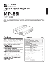
Installation of the Projector and Screen
To set the screen size and projection distance, see the illustration
and table below.
The projection distance shown in the table below represents the
full displayable resolution (1024 x 768).
a: Distance from the projector to the screen (± 10%).
Reference for Installation
CAUTION
• Install the projector in a suitable environment as indicated in this manual.
• If you use a metallic hardware support to mount this unit, be sure to ground it to avoid a risk of
fire or electrical shock..
Connect the ground terminal of the AC inlet of this unit to the ground terminal provided in the
building using an optional three-core power supply cord.
• Always use the projector in a horizontal position. If you operate the projector with its lens
upwards, its lens downwards or to the side, the heat generated inside the projector may build up
and cause malfunctions or damage. Never block the ventilation holes.
• Do not install the projector in a smoky environment, since smoke residue may accumulat on crit-
ical parts (i.e. LCD panel, lens, etc.).
Angle Adjustment
Use the foot adjusters located on the bottom of the projector to adjust the projection angle. This
angle can be adjusted within approximately 0° to 9°.
• Lift up the front side of the projector, then press the button of the foot adjuster to adjust the angle
of projection.
• To lock the foot adjuster at the desired angle, release the button.
• Rotate the screw of the foot adjuster to precisely adjust it. Do not use force, since this could dam-
age the adjuster or result in a failure of the lock.
CAUTION
• Do not release the foot adjuster button unless you are holding the projector securely.
Screen size
[inches (m)]
a [inches (m)]
Min. Max.
40 (1.0) 62 (1.6) 82 (2.1)
60 (1.5) 94 (2.4) 123 (3.1)
80 (2.0) 127 (3.2) 164 (4.2)
100 (2.5) 160 (4.1) 205 (5.2)
120 (3.0) 192 (4.9) 246 (6.3)
150 (3.8) 241 (6.1) 308 (7.8)
200 (5.0) 323 (8.2) 411 (10.4)
Side View
Top View
Foot Adjusters
Press the foot adjuster button
Rear Foot Adjuster

8
ViewSonic PJ751
Ports and Cables
Refer to this table to determine which projector port and cable to use for connecting to a given
device. Use this table for determining which cables to prepare.
Function Terminal Cable
RGB input RGB IN 1 Accessory or optional RGB cable with D-
sub 15-pin shrink jack and inch thread
screws.
RGB IN 2
RGB output RGB OUT
Audio input
(from the computer)
AUDIO IN 1
(interlocked with RGB IN 1)
Optional audio cable with stereo mini-
jack
AUDIO IN 2
(interlocked with RGB IN 2)
USB mouse control USB Optional USB cable
PS/2 mouse control CONTROL Accessory PS/2 mouse cable
ADB mouse control Optional ADB mouse cable
Serial mouse control Optional serial mouse cable
RS/232C communication Optional RS-232C mouse cable
S-video input S-VIDEO IN Optional S-video cable with mini DIN 4-
pin jack
Video input VIDEO IN Accessory audio/video cable
Component video input COMPONENT VIDEO Y Accessory component video cable
COMPONENT VIDEO Cb/Pb
COMPONENT VIDEO Cr/Pr
Audio input
(from video equipment)
AUDIO IN L Accessory audio/video cable or optional
audio cable with RCA jack
AUDIO IN R
Audio output AUDIO OUT Optional audio cable with stereo mini-
jack

ViewSonic PJ751
9
Power Connection
If the power cord is not compatible with the local AC outlet standard, contact your local dealer or
ViewSonic Corp to obtain the correct power cord..
Connect the AC inlet of the projector firmly to the power outlet with the power cord.
CAUTION
• Be alert when handling the power cord. Do not
bend the cord at a sharp angle or lay it under sharp
heavy objects that could cut the insulation.
• Plug the power connector securely to an AC wall
outlet.
Connecting Your Devices
NOTE: When connecting the projector to a notebook computer, set it so as to activate the RGB
external image output (setting it to CRT display or to simultaneous LCD and CRT display). For more
information, refer to the instruction manual of the notebook computer.
Plug & Play
This projector is compatible with VESA DDC 1/2B. Plug & Play is possible by connecting to a com-
puter that is compatible with VESA DDC (Display Data Channel).
Use this function by connecting the accessory RGB cable with RGB IN 1 terminal (DDC 1/2B com-
patible). Plug & Play may not operate by any other connection.
NOTE:
• Plug & Play is a system configured with peripheral equipment which includes a computer, display
and an operating system.
• This projector is recognized as a Plug & Play monitor. Load the driver contained in the CD Wiz-
ard included with the unit.
Power
outlet
AC inlet
Power cord
DVD Player
Display
Monitor
S-Video Tape
Recorder
Computer
(notebook)
Speaker with
amplifier
Computer (desktop)

10
ViewSonic PJ751
Connecting to a Computer
ATTENTION: Whenever attempting to connect a laptop computer to the projector, be sure to acti-
vate the laptop's RGB external image output (set the laptop to CRT display or to simultaneous LCD
and CRT display). For details on how this is done, please refer to the laptop computer’s instruction
manual of the corresponding laptop computer.
NOTE:
• Some computers may have multiple display screen modes. The use of some of these modes may
not be possible with this projector.
• For some RGB input modes, the optional Mac adapter is necessary.
AUDIO cable
RGB cable
AUDIO IN
AUDIO OUT
RGB IN
Analogue
RGB OUT
AUDIO IN
AUDIO OUT
AUDIO cable
RGB cable
RGB IN
Analogue
RGB OUT
USB IN
USB OUT
CONTROL IN
CONTROL OUT
MOUSE cable
USB cable
If connecting to a
USB port equipped
computer
Laptop computer
Desktop computer

ViewSonic PJ751
11
Connecting to a DVD Player or VCR
S-VIDIO OUT
S-VIDIO IN
COMPONENT VIDEO IN COMPONENT VIDEO OUT
AUDIO/VIDEO IN AUDIO/VIDEO OUT
AUDIO/VIDEO cable
COMPONENT cable
S-VIDEO cable
If using a S-video
connection
If using a component
video connection
If using an audio/video
connection
DVD player
VCR
S-VIDIO OUT
S-VIDIO IN
AUDIO/VIDEO IN
AUDIO/VIDEO OUT
AUDIO/VIDEO cable
S-VIDEO cable
If using a S-video
connection

12
ViewSonic PJ751
Connecting to a Display Monitor
RGB OUT
RGB IN
RGB cable
Display monitor

ViewSonic PJ751
13
OPERATION
Power ON
1 Check to be sure the power cord is connected correctly.
2 Set the power switch to [I]. When the standby mode is selected, the POWER indicator is orange.
3 Press the STANDBY/ON button on the control panel or the remote control device. The warm-up
starts and the POWER indicator blinks green.
4 The POWER indicator stops blinking and turns green when the power is on.
5 Remove the lens cap.
6 Adjust picture size using the ZOOM Knob.
7 Adjust focus with the FOCUS Ring.
Power OFF
1 Press the STANDBY/ON button on the control panel or the remote control device. The message
"Power off?" will appear on the screen. The message will disappear by any operation or if no
operation is carried out for 5 seconds. During this message indication, press the STANDBY/ON
button again. The projector lamp is turned off and the lamp will cool down. The POWER indica-
tor blinks orange when the lamp cools down. Pressing the STANDBY/ON button has no effect
while the POWER indicator is blinking.
2 The system goes into the Standby mode after cooling, then the POWER indicator stops blinking
and changes to orange. Check to be sure the indicator is orange then set the power switch to [0].
3 The POWER indicator is extinguished when power is off. Be sure to replace the lens cap.
NOTE:
• Except in emergencies, follow the above-mentioned procedure for turning the power off. Incor-
rect procedure will shorten the life of the projector lamp and LCD panel.
• To prevent any trouble, turn the projector on/off when the computer or video tape recorder is
OFF. Providing a RS-232C cable is connected, turn on the computer before switching on the pro-
jector.
POWER Indicator
Power Switch Lens cap
FOCUS Ring
ZOOM Knob
STANDBY/ON
Button
STANDBY/ON Button

14
ViewSonic PJ751
Selecting an Input Signal
Adjusting Image Size and Focus
Use the zoom ring to adjust the screen size
Use the focus ring to focus the picture
Using the remote control
If selecting RGB input
Press the RGB button
Press this button to toggle between the devices
connected to RGB IN 1 and 2. As illustrated
below, each time you press the RGB button, the
projector switches between RGB IN 1 and 2.
Select the signal you wish to project.
If selecting video input
Press the VIDEO button
Press this button to toggle between the devices
connected to VIDEO IN, SVIDEO IN and
COMPONENT VIDEO. As illustrated below,
each time you press the VIDEO button, the pro-
jector switches between VIDEO IN, S-VIDEO
IN and COMPONENT VIDEO. Select the sig-
nal you wish to project.
Using the projector's control panel
Press the INPUT button
As illustrated below, each time you press the
INPUT button, the projector switches between
its input signal ports. Select the signal you wish
to project.
RGB IN 1
RGB IN 2
VIDEO IN
COMPONENT VIDEO S-VIDEO IN

ViewSonic PJ751
15
Adjusting the Volume
1 Press the VOLUME button
As illustrated on the right, a dialog box will appear on the screen to
aid you in adjusting the volume.
2 Press the , buttons to adjust the volume
Press the VOLUME button again to close the dialog box and com-
plete this operation. (Even if you don't do anything, the dialog box
will automatically disappear after a few seconds.)
Temporarily Muting the Sound
1 Press the MUTE button
As illustrated on the right, a dialog will appear on the screen indicat-
ing that you have muted the sound. Press the VOLUME button to
close the dialog box. (Even if you don't do anything, the dialog box
will automatically disappear after a few seconds.)
2 Press the MUTE button once again to restore the sound.
Press this to increase the volume
Press this to decrease the volume

16
ViewSonic PJ751
Adjusting the Image Position
1 Press the POSITION button
As illustrated on the right, a dialog box will appear on the screen to aid
you in adjusting the position.
2 Use the , , , buttons to adjust the position
When you want to initialize the position, press the RESET button dur-
ing adjustment.
Press the POSITION button again to close the dialog box and com-
plete this operation. (If no activity is detected, the dialog will automat-
ically disappear after a few seconds.)
This function is only available for RGB IN 1/2 input.
Control Panel

ViewSonic PJ751
17
Using the Automatic Adjustment Feature
Press the AUTO button
Automatic Adjustment for RGB Input
Horizontal position (H. POSIT), vertical position (V. POSIT), clock
phase (H. PHASE) and horizontal size (H. SIZE) are automatically
adjusted. Make sure that the application window is set to its maximum
size prior to attempting to use this feature. Dark pictures may still be
incorrectly adjusted. Use a bright screen when adjusting.
Automatic Adjustment for Video Input
The input signal with best quality will be selected automatically.
This feature is available only if VIDEO is set to AUTO in the INPUT
menu.
NOTE:
• The automatic adjustment operation requires approximately 10 seconds. Certain input signals
may not function properly during this adjustment.
/