Page is loading ...

OM-2094
110100
Revised 01/01
Revised 02/01
Revised 03/01
Revised 05/01
Revised 06/01
Revised 07/01
Revised 08/01
1.
Hobart Brothers Company (hereinafter called HOBART) warrants that each new and unused Hobart Ground
Power Equipment, (hereinafter called the PRODUCT) is of good workmanship and is free from mechanical defects,
Operation and Maintenance Manual
Hobart Brothers Company
Ground Power Division
Troy, Ohio 45373
U.S.A.
Jet-Ex 5D Generator Sets
Series 500285
To Order Parts Call 1-888-702-5326 - https://monsterfloorequipmentparts.com

1. Hobart Brothers Company (hereinafter called HOBART) warrants that each new and unused Hobart Ground
Power Equipment, (hereinafter called the PRODUCT) is of good workmanship and is free from mechanical defects,
provided that (1) the PRODUCT is installed and operated in accordance with the printed instructions of HOBART,
(2) the PRODUCT is used under the normal operating conditions for which it is designed, (3) the PRODUCT is not
subjected to misuse, negligence or accident, and (4) the PRODUCT receives proper care, lubrication, protection,
and maintenance under the supervision of trained personnel.
2. This warranty expires 15 months after shipment by HOBART to the first user, or 12 months after installation,
whichever first occurs.
3. This warranty does not apply to: primary and secondary switch contacts, cable connectors, carbon brushes, fuses,
bulbs, and filters unless found to be defective prior to use.
4. Hobart DOES NOT WARRANT THE FOLLOWING COMPONENTS: Engines (gasoline or diesel),storage
batteries, engine starters generators, alternators, regulators, governors, tires, axles,transmissions, and cable
retrieving devices. Many of the foregoing components are warranted directly by the manufacturer to the first user
and serviced by a worldwide network of distributors and others authorized to handle claims for component
manufacturers. A first user’s claim should be presented directly to such an authorized component service outlet.
In the event any component manufacturer has warranted its component to HOBART and will not deal directly with
a first user then HOBART will cooperate with the first user in the presentation of a claim to such manufacturer.
Under NO circumstances does HOBART assume any liability for any warranty claim against or warranty work
done by or in behalf of any manufacturer of the foregoing components.
5. This warranty is extended by HOBART only to the purchaser of new PRODUCTS from HOBART or one of its
authorized distributors. The PRODUCTS purchased under this warranty are intended for use exclusively by the
buyer and his employees and by no other persons and, therefore, there shall be no third party beneficiary to this
warranty.
6. A claim of defects in any PRODUCT covered by this warranty is subject to HOBART factory inspection and
judgment. HOBART’S liability is limited to repair of any defects found by HOBART to exist, or at HOBART’S
option the replacement of the defective product, F.O.B. factory, after the defective product has been returned by
the purchaser at its expense to HOBART’S shipping place. Replacement and exchange parts will be warranted for
the remainder of the original Warranty, or for a period of ninety (90) days, whichever is greater.
7. UNDER NO CIRCUMSTANCES whatsoever shall HOBART and its authorized distributors be liable for any special
or consequential damages, whether based on lost goodwill, lost resale profits, work stoppage impairment of other
goods or otherwise, and whether arising out of breach of any express or implied warranty, breach of contract,
negligence or otherwise, except only in the case of personal injury as may be required by applicable law.
8. Continued use of the PRODUCT(S) after discovery of a defect VOIDS ALL WARRANTIES.
9. Except as authorized in writing, this warranty does not cover any equipment that has been altered by any party
other than HOBART.
10. THERE ARE NO WARRANTIES WHICH EXTEND BEYOND THE DESCRIPTION ON THE FACE HERE OF.
HOBART MAKES NO WARRANTIES, EXPRESSED OR IMPLIED, OF MERCHANTABILITY OR FITNESS FOR
A PARTICULAR PURPOSE.
11. HOBART neither assumes nor authorizes any person to assume for HOBART any liability in connection with the
PRODUCTS sold, and there are no oral agreements or warranties collateral to or affecting this written Warranty.
This warranty and all undertakings of HOBART thereunder shall be governed by the laws of the State of Ohio,
United States of America.
HOBART BROTHERS COMPANY, TROY, OHIO, U.S.A.
GROUND POWER DIVISION
WARRANTY
WARNING
AT ALL TIMES, SAFETY MUST BE CONSIDERED AN IMPORTANT FACTOR IN THE INSTALLATION,
SERVICING AND OPERATION OF THE PRODUCT, AND SKILLED, TECHNICALLY QUALIFIED PERSONNEL
SHOULD ALWAYS BE EMPLOYED FOR SUCH TASKS.
To Order Parts Call 1-888-702-5326 - https://monsterfloorequipmentparts.com

Safety Warnings and Cautions
CALIFORNIA PROPOSITION 65 - DIESEL ENGINES. Diesel engine exhaust
and some of its constituents are known to the State of California to cause
cancer, birth defects and other reproductive harm.
ELECTRIC SHOCK can KILL. Do not touch live electrical parts.
ELECTRIC ARC FLASH can injure eyes, burn skin, cause equipment damage,
and ignite combustible material. DO NOT use power cables to break load and
prevent tools from causing short circuits.
IMPROPER PHASE CONNECTION, PARALLELING, OR USE can damage
this and attached equipment.
Protect all operating personnel. Read, understand, and follow all instructions in
the Operating/Instruction Manual before installing, operating, or servicing the
equipment. Keep the manual available for future use by all operators.
1.
General
Equipment that supplies electrical power can cause serious injury or death, or damage to other
equipment or property. The operator must strictly observe all safety rules and take precautionary
actions. Safe practices have been developed from past experience in the use of power source
equipment. While certain practices below apply only to electrically-powered equipment, other practices
apply to engine-driven equipment, and some practices to both.
2.
Shock Prevention
Bare conductors, or terminals in the output circuit, or ungrounded, electrically-live equipment can fatally
shock a person. Have a certified electrician verify that the equipment is adequately grounded and learn
what terminals and parts are electrically HOT. Avoid hot spots on machine. Use proper safety clothing,
procedures, and test equipment.
The electrical resistance of the body is decreased when wet, permitting dangerous currents to flow
through it. When inspecting or servicing equipment, do not work in damp areas. Stand on a dry rubber
mat or dry wood, use insulating gloves when dampness or sweat cannot be avoided. Keep clothing dry,
and never work alone
a. Installation and Grounding of Electrically Powered Equipment
Equipment driven by electric motors (rather than by diesel or gasoline engines) must be installed
and maintained in accordance with the National Electrical Code, ANSI/NFPA 70, or other applicable
codes. A power disconnect switch or circuit breaker must be located at the equipment. Check the
nameplate for voltage, frequency, and phase requirements. If only 3-phase power is available,
connect any single-phase rated equipment to only two wires of the 3-phase line. DO NOT
CONNECT the equipment grounding conductor (lead) to the third live wire of the 3-phase line, as
this makes the equipment frame electrically HOT, which can cause a fatal shock.
November 1, 2000 Safety Warnings
Revised 03/01 Page 1
OM-2094 / Operation and Maintenance Manual
Jet-Ex 5D / Series 500285 / Generator Set
IMPORTANT
WARNING
WARNING
To Order Parts Call 1-888-702-5326 - https://monsterfloorequipmentparts.com

Always connect the grounding lead, if supplied in a power line cable, to the grounded switch box or
building ground. If not provided, use a separate grounding lead. Ensure that the current (amperage)
capacity of the grounding lead will be adequate for the worst fault current situation. Refer to the
National Electrical Code ANSI/NFPA 70 for details. Do not remove plug ground prongs. Use
correctly mating receptacles.
b. Output Cables and Terminals
Inspect cables frequently for damage to the insulation and the connectors. Replace or repair
cracked or worn cables immediately. Do not overload cables. Do not touch output terminal while
equipment is energized.
3.
Service and Maintenance
This equipment must be maintained in good electrical and mechanical condition to avoid hazards
stemming from disrepair. Report any equipment defect or safety hazard to the supervisor and
discontinue use of the equipment until its safety has been assured. Repairs should be made by
qualified personnel only.
Before inspecting or servicing electrically-powered equipment, take the following precautions:
a. Shut OFF all power at the disconnecting switch or line breaker before inspecting or servicing the
equipment.
b. Lock switch OPEN (or remove line fuses) so that power cannot be turned on accidentally.
c. Disconnect power to equipment if it is out of service.
d. If troubleshooting must be done with the unit energized, have another person present who is trained
in turning off the equipment and providing or calling for first aid.
4.
Fire And Explosion Prevention
Fire and explosion are caused by electrical short circuits, combustible material near engine exhaust
piping, misuse of batteries and fuel, or unsafe operating or fueling conditions.
a. Electrical Short Circuits and Overloads
Overloaded or shorted equipment can become hot enough to cause fires by self destruction or by
causing nearby combustibles to ignite. For electrically-powered equipment, provide primary input
protection to remove short circuited or heavily overloaded equipment from the line.
b. Batteries
Batteries may explode and/or give off flammable hydrogen gas. Acid and arcing from a ruptured
battery can cause fires and additional failures. When servicing, do not smoke, cause sparking, or
use open flame near the battery.
c. Engine Fuel
Use only approved fuel container or fueling system. Fires and explosions can occur if the fuel tank
is not grounded prior to or during fuel transfer. Shut unit DOWN before removing fuel tank cap. DO
NOT completely fill tank, because heat from the equipment may cause fuel expansion overflow.
Remove all spilled fuel IMMEDIATELY, including any that penetrates the unit. After clean-up, open
equipment doors and blow fumes away with compressed air.
5.
Toxic Fume Prevention
Carbon monoxide - Engine exhaust fumes can kill and cause health problems. Pipe or vent the exhaust
fumes to a suitable exhaust duct or outdoors. Never locate engine exhausts near intake ducts of air
conditioners.
6.
Bodily Injury Prevention
Serious injury can result from contact with fans inside some equipment. Shut DOWN such equipment
for inspection and routine maintenance. When equipment is in operation, use extreme care in doing
necessary trouble-shooting and adjustment. Do not remove guards while equipment is operating.
Safety Warnings November 1, 2000
Page 2 Revised 03/01
OM-2094 / Operation and Maintenance Manual
Jet-Ex 5D / Series 500285 / Generator Set
To Order Parts Call 1-888-702-5326 - https://monsterfloorequipmentparts.com

7. Medical and First Aid Treatment
First aid facilities and a qualified first aid person should be available for each shift for immediate
treatment of all injury victims. Electric shock victims should be checked by a physician and taken to a
hospital immediately if any abnormal signs are observed.
Call physician immediately. Seek additional assistance. Use First Aid techniques
recommended by American Red Cross until medical help arrives.
IF BREATHING IS DIFFICULT, give oxygen, if available, and have victim lie
down. FOR ELECTRICAL SHOCK, turn off power. Remove victim; if not
breathing, begin artificial respiration, preferably mouth-to-mouth. If no detectable
pulse, begin external heart massage. CALL EMERGENCY RESCUE SQUAD
IMMEDIATELY.
8.
Equipment Precautionary Labels
Inspect all precautionary labels on the equipment monthly. Order and replace all labels that cannot be
easily read.
November 1, 2000 Safety Warnings
Revised 03/01 Page 3
OM-2094 / Operation and Maintenance Manual
Jet-Ex 5D / Series 500285 / Generator Set
EMERGENCY
FIRST AID
To Order Parts Call 1-888-702-5326 - https://monsterfloorequipmentparts.com

This page intentionally left blank.
Safety Warnings November 1, 2000
Page 4 Revised 03/01
OM-2094 / Operation and Maintenance Manual
Jet-Ex 5D / Series 500285 / Generator Set
To Order Parts Call 1-888-702-5326 - https://monsterfloorequipmentparts.com

Introduction
This manual contains operation and service information for 28.5 V DC Generator sets identified as Jet-Ex 5D.
These units are available as stationary, skid- mounted units, or they may be trailer-mounted for portability.
Both versions are available with 14 V DC output capability.
Most information in the manual applies to the 28.5 V Jet-Ex 5D in general. Information which applies to
options and special equipment are listed in Appendix A.
The primary purpose of the manual is to provide information and instructions to experienced operators,
electricians, and mechanics who are not familiar with this equipment. The intent of the manual is to guide
and assist operators and maintenance personnel in the proper use and care of the equipment.
Read the instructions before starting the unit. Learn to use the manual and to locate information contained in
it.
The Table of Contents, which follows this Introduction, lists all Chapters, Sections, and the paragraph titles
within each Section. The location of each listing is identified by Chapter, Section and page number.
Each Chapter is divided into as many Sections as necessary. Sections are always referred to by a
combination Chapter-Section number, for example: 2-3 refers to Chapter 2, Section 3.
The material within each Section is divided into main subjects with applicable paragraph headings and
sub-headings as required. For example, a portion of the Description Section might logically follow this
arrangement and paragraphing:
Section 1. Description
1. Engine, Generator and Controls
a. Interior Panel
(1) Protective devices
a. Overload relay
(2) Contactors
Page numbers do not run consecutively throughout the manual. Each page is identified by the
Chapter-Section number in which it appears, and by a page number within the Chapter-Section. Therefore,
the first page in each Section is page 1. These identifying numbers appear in the lower, outside corner of
each page. Each page also bears a date located in the corner opposite the page number. This date is either
that of original issue, or of the latest revision. Any revision to the original text is identified by a heavy black line
in the left-hand margin. Illustrations follow a numbering system similar to page numbering. The first Figure in
each Section is Figure 1.
All tables, charts, as well as illustrations, are identified by Figure numbers to avoid confusion.
The general location of any particular information can be found quickly by running through the Table of
Contents. For example: to locate any adjustment information, a quick look at the Table of Contents shows that
“Adjustment / Test” is located in Chapter 2, Section 3, (shown as 2-3).
November 1, 2000 Introduction
Revised 03/01 Page 1
OM-2094 / Operation and Maintenance Manual
Jet-Ex 5D / Series 500285 / Generator Set
To Order Parts Call 1-888-702-5326 - https://monsterfloorequipmentparts.com

Portions of the text are referred to by identifying the paragraph in which the referenced material may be
found. When referenced material is located in the same Chapter/Section as the reference, only the paragraph
identification is given, for example: (Ref. Para. 1, A) means that the material is to be found in paragraph 1, A,
of the same Section.
When referenced material is located in another Chapter/Section, both the Chapter and Section numbers and
the paragraph identification are given, for example: (Ref. 1-2, Para. 1, A) means that the referenced material
is located in Chapter-Section 1-2, and paragraph 1,a. within that Chapter-Section.
Components shown in illustrations, and the illustrations themselves, are referenced in a similar manner.
When this type of reference is made, the item number of the part and the Figure number in which it appears
are given, for example: (2, Fig.3) refer to item number 2 in illustration Figure 3 of the same Chapter/Section.
When a referenced figure appears in another Chapter/Section, the reference will include the Chapter/Section
number, for example: (2-3, 1, Fig. 4) tells the user that the information is in Chapter/Section 2-3, and to refer
to item 1 in Figure 4.
Once a Figure number reference has been established, the Figure number is not repeated and only the item
numbers of the parts involved are referenced, for example: “Loosen screw (2, Fig.6) slide out connector (4),
and remove brush (6).
When an item number is referenced without a Figure number, it always applies to the last preceding Figure
number mentioned in the text.
A collection of manufacturer’s literature is supplied as part of the information package.
If you have any questions concerning your Hobart Ground Power equipment, immediately contact our
Service Department by mail, telephone or FAX.
Write: Hobart Brother Company
Ground Power Division
Service Department
1177 Trade Road East
Troy, Ohio 45373
U.S.A.
In U.S.A. Call: (800) 422-4166 (Parts)
(800) 422-4177 (Service)
From Foreign Countries Call: (937) 332-5050 (Parts)
(937) 332-5060 (Service)
FAX: (937) 332-5121
(800) 367-4945 Toll Free in U.S.A.
Introduction November 1, 2000
Page 2 Revised 03/01
OM-2094 / Operation and Maintenance Manual
Jet-Ex 5D / Series 500285 / Generator Set
To Order Parts Call 1-888-702-5326 - https://monsterfloorequipmentparts.com

Table of Contents
Chapter 1. Description/Operation
Section 1. Description 1
General 1
Special Features 1
Standard 1
Options 1
Orientation 4
Identification 4
Canopy 4
Engine, Generator, and Controls 4
General 4
Engine 4
Generator 9
Rectifier Assembly 9
Ammeter Shunt 9
Contactor 9
Control Box Assembly (Front) 11
Control Box Assembly (Inside) 15
Emergency Sutdown Device 15
Section 2. Preparation for Use, Storage or Shipping 1
Preparation for Use 1
General 1
Inspection/Check 1
Output Cable Requirements and Installation 1
Preparation for Storage 3
General 3
Temporary Storage 3
Long Time Storage 3
Preparation for Shipping 3
Section 3. Operation 1
General 1
Operating the Generator Set 1
Pre-start Inspection 1
Pre-start Instructions 1
Starting The Engine 3
November 1, 2000 Table of Contents
Revised 03/01 Page 1
OM-2094 / Operation and Maintenance Manual
Jet-Ex 5D / Series 500285 / Generator Set
To Order Parts Call 1-888-702-5326 - https://monsterfloorequipmentparts.com

Generator Operation 3
Deliver Power 3
Stop Operation (Shutdown) 3
Adverse Weather Precautions 4
Chapter 2. Servicing / Troubleshooting
Section 1. Maintenance Inspection/Check 1
General 1
Maintenance Schedule 1
General 1
Maintenance Schedule Check Sheet 1
Time Intervals 1
Engine and Related Components 1
Inspection and Cleaning 3
Section 2. Maintenance Procedures 1
General 1
Lubrication 1
General 1
Lubrication Chart 1
Generator 1
Generator Controls 1
Engine 1
Servicing the Air Cleaner 4
Air Filter Cartridge Removal 4
Air Filter Cartridge Installation 4
Servicing the Fuel Filter 4
Drive Belt Service 4
Engine Cooling System 4
Radiator Cap Removal 5
Rust Inhibitor 5
Antifreeze 5
Battery Service 5
General 5
Battery Location and Accessibility 5
Battery Care 5
Liquid Level (If Battery is not Maintenance Free) 5
Cleaning the Battery 6
Testing a Battery 6
Generator Maintenance 7
General 7
Brush Service 7
Generator Revolving Field Brush Replacement 7
Table of Contents November 1, 2000
Page 2 Revised 03/01
OM-2094 / Operation and Maintenance Manual
Jet-Ex 5D / Series 500285 / Generator Set
To Order Parts Call 1-888-702-5326 - https://monsterfloorequipmentparts.com

Section 3. Adjustment/Test 1
General 1
Testing the Generator Set 1
Pre-operational Test Procedures 1
Operational Tests 3
Voltage Regulator Adjustment 4
28.5 Volt Adjustment 4
Line Drop Compensation 4
Section 4. Troubleshooting Procedures 1
General 1
Troubleshooting Chart 1
Description 1
Use of the Troubleshooting Chart 1
Equipment for Troubleshooting 1
Safety Precautions 1
Diagrams 1
Connections and Wiring 1
Section 5. Troubleshooting Charts 1-8
Chapter 3. Major Overhaul
Section 1. Flexible Coupling 1
General 1
Coupling Screws (Routine Coupling Maintenance) 2
Disassembly 3
Separate Engine and Generator 3
Remove Coupling Assembly 3
Coupling Service 4
Coupling Installation and Reassembly of Engine Generator 5
Cleaning 5
Assembly 5
Run-In and Periodic Check 7
Chapter 4. Illustrated Parts List
Section 1. Introduction 1
General 1
Purpose 1
Arrangement 1
November 1, 2000 Table of Contents
Revised 03/01 Page 3
OM-2094 / Operation and Maintenance Manual
Jet-Ex 5D / Series 500285 / Generator Set
To Order Parts Call 1-888-702-5326 - https://monsterfloorequipmentparts.com

Explanation of Parts List 1
Contents 1
Parts List Form 1
Section 2. Manufacturer’s Codes 1
Explanation of Manufacturer’s (Vendor) Code List 1
Section 3. Parts List 1
Explanation of Parts List Arrangement 1
Symbols and Abbreviations 1
Section 4. Numerical Parts List 1
Explanation of Numerical Parts List 1
Chapter 5. Manufacturer’s Literature
Appendix A. Options / Features
Table of Contents November 1, 2000
Page 4 Revised 03/01
OM-2094 / Operation and Maintenance Manual
Jet-Ex 5D / Series 500285 / Generator Set
To Order Parts Call 1-888-702-5326 - https://monsterfloorequipmentparts.com

Chapter 1. Description/Operation
Section 1. Description
1. General
The Jet-Ex 5D units (Figure 1) covered in this manual are diesel engine driven, self-contained
generator sets manufactured by Hobart Brothers Company, Ground Power Division, Troy, Ohio U.S.A.
A basic unit is identified by a Series Number - 500285 - plus a dash number which defines a specific
configuration. The Series Number, plus the dash number, make up the Specification Number.
Part Number Mounting Configuration
500285-001
Trailer Mounted with Cable
Trays
500285-002
Stationary Mounted with
Cable Hangers
Specification No. 500285-001 covers a trailer mounted unit rated at 28.5 Volts DC output. It is equipped
with a sheet metal canopy and four hinged engine compartment doors. Various options are available
for use with the basic unit. A few of these options are listed in paragraph 2.B below, but the complete
list of options are located in Appendix A.
The basic generator set is designed to generate and deliver 28.5 Volts DC power to an aircraft when its
on-board generators are shut down. In addition to providing continuous, regulated power to the aircraft,
the unit is also designed for starting any fixed-wing aircraft or helicopter which is equipped with an
external 28.5 Volts DC power receptacle.
2.
Special Features
a. Standard
The “Soft-Start” current limiting feature, recommended by most aircraft engine manufacturers,
provides the operator with controls to limit the inrush current to the aircraft engine’s starter. When
the operator presets this control, the generator will provide constant voltage to the preset current
value. The more current is increased beyond the preset current value, the voltage will decrease to a
minimum of 14 volts DC, after which the voltage will remain constant as more current may be
delivered beyond the preset current value. Limiting inrush current is recommended by most engine
manufacturers to protect the aircraft engine’s starter shear section. The current limiting control is
continuously adjustable from 300 amperes, which is recommended for helicopter and small turbine
starting, to 2000 amperes, required for starting larger aircraft engines when the control is turned
fully clockwise.
b. Options (See Appendix A for complete list)
Chapters 1-5 of this manual describes a basic “no options” generator set. Appendix A lists the
options available for this unit. Below are the mounting configurations.
November 1, 2000 Chapter 1-1
Revised 07/01 Page 1
OM-2094 / Operation and Maintenance Manual
Jet-Ex 5D / Series 500285 / Generator Set
To Order Parts Call 1-888-702-5326 - https://monsterfloorequipmentparts.com

Chapter 1-1 November 1, 2000
Page 2 Revised 07/01
OM-2094 / Operation and Maintenance Manual
Jet-Ex 5D / Series 500285 / Generator Set
Jet-Ex 5D Generator Set
Figure 1
To Order Parts Call 1-888-702-5326 - https://monsterfloorequipmentparts.com

Unit with Stationary Mount (500285-002)
Length 68” (172.7 cm)
Width 37” (94 cm)
Height 46” (116.8 cm)
Weight (dry fuel tank) 2400 lbs (1088.6 kg) Approx.
Unit with Trailer and Cable Trays (500285-001)
Length 76.3” (193.8 cm)
Width 67” (170.1 cm)
Height 62” (157.5 cm)
Weight (dry fuel tank) 2670 lbs (1211 kg) Approx.
Ground Clearance 14” (35.6 cm)
Generator
Output Power Rating 17.1 kW
Voltage 28.5 volts DC
Rated Load Capacity 800 amperes continuous at 28.5 volts DC
Starting Current Capacity 2000 amperes maximum
Current Limiting Capability 300 to 2000 amperes, continuously adjustable
Operating Speed 2500 +/-50 RPM
Engine
Manufacturer Cummins Diesel
Model 4BT3.9
Type 4-cylinder, 4-stroke, direct injection
Fuel-Diesel recommended ASTM D975 66T Numbers 1D or 2D
Displacement 238 cubic inches (3.9 liters)
Rated Power at 2200 RPM 100 Horsepower (75 kW)
Oil Capacity (without filter change) 11.5 quarts (10.9 liters)
Coolant Capacity - engine only 7.4 U.S. Quarts (7 liters)
Coolant Capacity - system 4.5 U.S Gallons (17 liters)
Electrical System 12 volt DC, negative ground
Governed Speed at No Load 2500 +/- 50 RPM
Idle Speed 1000 +/- 50 RPM
Fuel Tank Capacity 20.5 U.S. gallons (77.6 liters)
Protective Devices
Generator 28.5 volt over voltage module trips at 32 to 34 volts.
Engine
Water Temp. Switch opens engine circuit at 210º F (98.8º
C)
Low Oil Pressure Switch opens at 20 PSI (138 kPa).
November 1, 2000 Chapter 1-1
Revised 07/01 Page 3
OM-2094 / Operation and Maintenance Manual
Jet-Ex 5D / Series 500285 / Generator Set
To Order Parts Call 1-888-702-5326 - https://monsterfloorequipmentparts.com

3. Orientation
The radiator end of the Jet-Ex 5D is the front. Right and left are determined by standing at the rear of
the unit, facing it. The control panel is located at the rear.
4.
Identification
The Jet-Ex 5D unit is identified by Specification numbers as described in paragraph 1. There may be
any number of Generator sets with the same Specification number. Individual machines are identified
by a Serial number, assigned to one machine only.
Each generator set has an Identification plate attached inside the control box. This nameplate lists the
machines Model No. (Jet-Ex 5D), Specification No., Serial No., and electrical rating.
If any of the options described in paragraph 2.b. are included, they will be listed by name and part
number on a separate option nameplate located next to the Identification plate.
5.
Canopy
The standard canopy is a sheet metal enclosure which protects the engine, generator, and electrical
controls. It has four hinged doors to provide access for service and maintenance. A bolted on panel at
the rear (below the control box) provide access to the rectifier assembly. A Lexan window is mounted in
front of the control panel to allow observation of the instruments while protecting them from the
weather.
6.
Engine, Generator, and Controls
a. General
The engine (7, Figure 2) and generator (5) are mounted on a welded steel frame (6). A fuel tank
support (1) located at the rear of the unit supports the fuel tank (2) and provides a mounting frame
for the load contactor (10) and output terminals. The radiator (7, Figure 4) is mounted to the front
canopy and frame.
b. Engine
(1) General
The engine used in the Jet-Ex 5D generator set is a Cummins Model 4BT3.9 four-cylinder,
four-stroke, direct injection diesel engine. It has a 238 cubic inch (3.9 liter) cylinder displacement
and a 17.5:1 compression ratio. Engine firing order is 1-3-4-2.
A spring-loaded relief valve in the oil pump limits maximum pressure in the system. A full-flow oil
filter (3, Figure 3) cleans the oil before it enters the oil distributing system. A low oil pressure
switch is mounted on the engine block as a protective device. The fuel valve solenoid circuit is
wired through the contacts of this switch, which closes at 20 PSI (138 kPa). This prevents the
engine from continuing operation if oil pressure will not build up, and also shuts down the engine
if oil pressure drops radically during operation.
See the engine operator’s manual for additional engine specifications.
The generator and engine are mounted on a welded steel skid, and are enclosed by a sheet
metal canopy that bolts to the skid. Access to engine serviceable components (oil filter, air
cleaner, etc.) is through the doors on each side of the machine.
The rear panel is removable and permits access to the rectifier assembly.
Chapter 1-1 November 1, 2000
Page 4 Revised 07/01
OM-2094 / Operation and Maintenance Manual
Jet-Ex 5D / Series 500285 / Generator Set
To Order Parts Call 1-888-702-5326 - https://monsterfloorequipmentparts.com

November 1, 2000 Chapter 1-1
Revised 07/01 Page 5
OM-2094 / Operation and Maintenance Manual
Jet-Ex 5D / Series 500285 / Generator Set
27 1
3
4
5
6
9
8
10
1. Fuel Tank Support
2. Fuel Tank
3. Control Panel
4. Rectifier Assembly
5. Generator
6. Frame
7. Engine
8. Air Cleaner
9. Battery
10. Contactor
Generator Set Components
Figure 2
To Order Parts Call 1-888-702-5326 - https://monsterfloorequipmentparts.com

Chapter 1-1 November 1, 2000
Page 6 Revised 07/01
OM-2094 / Operation and Maintenance Manual
Jet-Ex 5D / Series 500285 / Generator Set
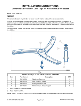
4
5
2
1
3
1. Muffler
2. Alternator
3. Oil filter
4. Starter
5. Starter solenoid
Generator Set Components
(Left Side)
Figure 3
To Order Parts Call 1-888-702-5326 - https://monsterfloorequipmentparts.com

November 1, 2000 Chapter 1-1
Revised 07/01 Page 7
OM-2094 / Operation and Maintenance Manual
Jet-Ex 5D / Series 500285 / Generator Set
267
1
4
5
3
1. Fuel filter
2. Air cleaner
3. Throttle control assembly
4. Oil pressure sender
5. Oil pressure switch 20 psi (138 kPA)
6. Water Temp. Switch
7. Radiator
Generator Set Components
(Right Side)
Figure 4
To Order Parts Call 1-888-702-5326 - https://monsterfloorequipmentparts.com

(2) Cooling fan
The cooling fan on the engine is designed to blow air out through the radiator rather than to draw
it in. This prevents hot air, heated by the engine, from entering the generator.
(3) Fuel system
The fuel system consists of a 20.5-gallon (77.6 liters) plastic fuel tank (2, Figure 2) with all the
necessary fittings and hoses.
(4) Alternator
The battery charging alternator (2, Figure 3) is rated at 65 amperes. The alternators
responsibility is to produce/regulate 12V DC for the generator sets internal electrical system.
(5) Starter solenoid
The starter solenoid (5, Figure 3) is mounted on the starter motor (4), on the right side of the
engine.
(6) Exhaust muffler (1, Figure 3)
This muffler helps deaden audible noise from the engine’s exhaust.
(7) Engine faults
The following is a table listing faults which may occasionally occur. Column two of the table
explains what happens in the engine’s circuitry when the fault occurs, and column three tells how
to return the generator set to service.
ENGINE FAULTS
Engine Fault Condition What This Fault Condition Does
To Put the Generator Set Back
into Service:
Over Temperature Automatically removes power
from the fuel valve solenoid and
shuts down the engine
a) Let the engine cool down
enough to check for low coolant
level and or faulty over
temperature switch. Restart
engine.
Low Oil Pressure Automatically removes power
from the fuel valve solenoid and
shuts down the engine
a) Let the engine cool down
enough to check for low oil level
and or faulty oil pressure switch.
Restart engine.
Clogged air cleaner or
other restriction in the
combustion air inlet.
Turns on the air cleaner
restriction indicating light
(16, Figure 5)
a) Replace clogged air filter if
needed; clean out the air intake
chamber. Restart engine.
Chapter 1-1 November 1, 2000
Page 8 Revised 06/01
OM-2094 / Operation and Maintenance Manual
Jet-Ex 5D / Series 500285 / Generator Set
To Order Parts Call 1-888-702-5326 - https://monsterfloorequipmentparts.com
/