SEE FIG. 19
Follow instructions in section ‘ELECTRICAL
COMPONENT ACCESS’, Steps 1 to 5.
1. Undo the locknut, which holds the overheat thermostat
to the bracket on the rear of the chassis.
2. Remove the 2 push on connectors from back of
overheat thermostat.
3. Remove the phial from the 2 spring clips on the rear of
the chassis.
4. Withdraw overheat thermostat from chassis.
5. Fit replacement overheat thermostat and assemble in
reverse order.
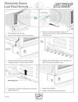
SEE FIG. 21
Follow instructions in section ‘ELECTRICAL
COMPONENT ACCESS’, Steps 1 to 5.
1. Undo the two screws on the front of the chassis which
holds the thermostat in place.
2. Remove the (2) push on connectors from back of
thermostat.
3. Open roasting oven door and using a screwdriver,
loosen the rear fixing screws and remove the front
fixing screw of the inner LH oven side to expose the
thermostat stat phial.
4. Slacken the single screw where the phial passes
through the roasting oven side and rotate the cover
plate to open the access hole.
5. Slacken the single screw on the phial securing bracket
and rotate the cover bracket.
6. Withdraw the capillary and phial from the oven.
7. Fit replacement thermostat and assemble in reverse
order.
To complete, follow instructions in RE-ASSEMBLE’,
Steps 1 to 5.
Follow instructions in section ‘ELECTRICAL
COMPONENT ACCESS’, Steps 1 to 4.
1. Remove timer by depressing retaining clips.
To complete follow instructions in section ‘RE-
ASSEMBLE’, Steps 2 to 5.
1. Locate the base of the control chassis into the bottom
of the doorway aperture, tilt the chassis backwards
into position and secure with (4) screws.
2. Thread the wires for the cooker timer through the
aperture and connect them onto the rear of the cooker
timer fitted in the outer panel.
3. Refix the outer panel in position and secure with the
(2) screws.
4. Replace the thermostat knob.
5. Replace the controls door.
Replacement of parts
(Electrical Controls)
TO FIT NEW OVERHEAT
THERMOSTAT
TO FIT NEW TIMER
RE-ASSEMBLE
20
Fig. 21 DESN 510546
DESN 511738 C
COOKER
THERMOSTAT
THERMOSTAT
PHIAL LOCATION
ORANGE
TO FIT NEW OVEN CONTROL
THERMOSTAT