Page is loading ...

Instruction Manual
LX850™ German Equatorial Mount Telescope System
With StarLock™


WARNING!
Never use a Meade
®
LX850
Telescope to look at the Sun!
Looking at or near the Sun will cause
instant and irreversible damage to your
eye. Eye damage is often painless, so there
is no warning to the observer that damage
has occurred until it is too late. Do not point
the telescope at or near the Sun. Do not
look through the telescope or Finder Scope
as it is moving. Children should always
have adult supervision while observing.
Travel Screw:
The LX850 f/8 ACF optical tube assembly (OTA) is
shipped from the factory with the focusing mechanism
protected by a travel screw. This screw secures the
primary mirror in a xed position during travel thereby
protecting the focusing mechanism from shock
damage. This screw is on the back cell of the OTA,
near the Crayford Focuser, and is identied by a dab of
red paint.
This screw must be removed before attempting to focus
the OTA. Failure in removal can result in damage to the
Crayford Focusing mechanism. Retain this screw for
future use as it is suggested that mirror be locked down
anytime the OTA is shipped.
Move the primary mirror to the travel position by rotating
the focuser knob counter clockwise until its travel limit
is reached. Reattach the travel screw and tighten until
rm. Do not over tighten.

® The name “Meade,” “AutoStar” and the Meade logo are
trademarks registered with the U.S. Patent and Trademark Ofce
and in principal countries throughout the world.
StarLock, Deep Sky Imager”, “LX850”, and “Tonight’s Best” are
trademarks of Meade Instruments Corp.
Protected by U.S. Patent:
US 6,392,799 and other Patents Pending
© 2013 Meade Instruments Corp.
Calibrate Home ............................25
StarLock Operation .........................25
StarLock Automatic Rate Calibration (ARC) ......26
StarLock and Mount Flexure..................26
AutoStar II Operation
The AutoStar II Handbox.....................27
AutoStar Navigation Exercise .................28
Example of Locating a Menu .................28
AutoStar II Menu Tree.......................29
Navigating AutoStar II .......................30
Object Menu ..............................30
Event Menu...............................31
Glossary Menu ............................31
Utilities Menu .............................32
Setup Menu...............................33
“Hot Button” Menu..........................35
StarLock Periodic Error Correction .............36
Advanced Autostar II Features
Adding Observing Sites .....................37
Creating User Objects.......................37
Using AutoStar to Find Objects not in Database...38
To GO TO a user-entered object...............39
Landmarks ...............................39
Identify ..................................40
Browse ..................................41
Alternate Polar Alignments
Two-Star Polar Alignment ....................42
Easy Polar Alignment .......................42
One-Star Polar Alignment ....................42
Align on Home ............................42
How to Drift Align LX850.....................42
Download the Latest Version
of AutoStar II Software....................43
StarLock Assisted PEC Training ...............43
Update Menu Option........................43
Erase Menu Option .........................43
On and Off Menu Options ....................43
Optional Accessories..........................44
Maintenance ................................46
Customer Service.............................46
Specications................................47
Appendix A:
Manual Drift Alignment ......................49
Appendix B:
StarLock Utility ............................50
Appendix C:
Automatic Rate Calibration (ARC) .............53
Appendix D:
Latitude Chart .............................54
Appendix E:
Advanced Coma-Free Optical System ..........55
Appendix F:
Initial Set-up Guide .........................56
Recycling:
How to recycle ................................58
Meade Warranty
One Year Limited Warranty .............. Back Cover
CONTENTS
Introduction
The LX850 Telescope ........................5
Telescope Features
Precision Machined German Equatorial Mount ....6
Faster, Sharper Optical System ................6
StarLock — Full-Time Automatic Guiding .........6
Key Features
Figure 1: Right View .........................7
Figure 2: Left View ..........................8
Figure 3: Detail RA Access ....................9
Figure 4: Detail StarLock Counterweight .........9
Figure 5: Detail Saddle Plate ..................9
Figure 6a: Telescope Control Panel ............10
Figure 6b: StarLock Control Panel .............10
LX850 Key Features ........................11
Assembly
Assembly Tools ............................13
Tripod Assembly . . . . . . . . . . . . . . . . . . . . . . . . . . . 13
Attach Mount Assembly to Tripod ..............14
Attach Counterweight Shaft ..................15
Attach Counterweights ......................15
Routing Connector Cables ...................15
Removing the Saddle .......................16
StarLock Cable ............................16
Attach the Control Module ...................17
DEC and RA Connecting Cables ..............17
Attach the Optical Tube Assembly (OTA) ........17
Attach Diagonal and Eyepiece ................18
Attach StarLock Assembly ...................18
Plug in the AutoStar II Handbox ...............19
Attach the Viewnder to the OTA ..............19
Mount Additional Accessories and Equipment ....19
Balancing the Telescope .....................19
Balancing the RA Axes ......................20
Balancing the DEC Axes.....................20
Balancing StarLock .........................20
Getting Started
Focusing & Aligning the Viewnder.............21
Focusing the Telescope .....................21
Slew Speeds ..............................22
Aligning for the First Time ....................22
Finding True North/alignment on Polaris.........22
One Star Alignment.........................23
Syncing Your Eyepiece/Camera Using Starlock ...23
Test your Collimation........................24
Collimation of the Optical System: ACF Models ...24

INTRODUCTION
The LX850 Telescope
Advanced Technology for the Astro Imager
Congratulations on receiving your new LX850 telescope. You’ll nd that this telescope system has all you need to
explore the Universe we live in. Designed from the ground up to be the ideal Astro-imaging platform, the LX850
incorporates several new revolutionary technologies that will change the way you observe and image. Available only
from Meade.
Drawing on over 40 years of experience and innovation, Meade Instruments introduces the latest in a long line of
advanced astronomical products: the LX850. Using revolutionary new technology, every aspect of this amazing
telescope system has been designed to deliver the new standard in astrophotographic and visual performance:
• Fast f/8 Advanced Coma-Free (ACF) optical systems on the 10”, 12” and 14” OTAs. These optics
produce wider, atter elds with no coma for pinpoint stars out to the edge of larger imaging sensors
or extreme wide angle eyepieces.
• 130mm 3-element, air-spaced apochromatic f/7 refractor with 3” Crayford-style 10:1 focuser.
Beautifully machined and nished with case. Optional 3” eld attener available.
• StarLock™ full-time automatic integrated guider assists with drift polar alignment, nds and centers
targets and then automatically locks onto a eld star as faint as 11th magnitude for one arcsecond
guiding. No separate computer, no guide star selection, no user focus. Just set up your camera and
image (patent pending).
• German Equatorial Mount made from machined aluminum and stainless steel with large bearing
surfaces and roller bearings in both axes for an extremely solid and stable platform.
• Internal Crayford-style primary mirror focusing system with a dual speed 7:1 focus control, on ACF
OTA’s, eliminates image shift and mirror op. Precise focus is a snap (patent pending)
If you are like us, you can’t wait to get outside under a dark sky to use your new LX850 telescope. We have
provided a Getting Started Guide that will get you up and running in the shortest amount of time possible. After
your rst experience, please sit down with this manual and read about all the advanced features that are available
to you with this telescope system. We are condent that the LX850 will keep you fascinated with the Universe and
entertained for many years to come.
Clear Skies,
The people at Meade
5
Introduction

Meade Instruments introduces the latest in a long line
of advanced astronomical products: the LX850™. Using
revolutionary new technology, every aspect of this
system has been designed to deliver the new standard
in astrophotographic and visual performance.
Precision Machined German
Equatorial Mount
Constructed of machined stainless steel and aircraft
grade 6061-T6 aluminum, the LX850 mount presents
a rock-solid platform with precision roller bearings on
both axes and a 1.75 inch stainless steel RA shaft. Its
.68 inch diameter brass worms and 5.8 inch diameter,
225-tooth aluminum gears deliver smooth, precise
movement with up to a 90 pound instrument load. Add
to this internal cabling, GPS and the AutoStar II fully-
computerized GoTo system with a database of over
144,000 objects. All this sets atop a new ultra-stable
tripod.
Faster, Sharper Optical System
Building on Meade’s award-winning Advanced Coma-
Free™ (ACF™) optics, the LX850 employs a fast f/8
optical system with high-contrast bafing that assures
crisp, pinpoint imaging to the very edge of the eld.
The all-new OTAs feature an internal Crayford-style,
zero image-shift focusing system with a two-speed,
7:1 control that rigidly holds the primary mirror (patent
pending). In addition, with the LX850’s optional large-
format, three-element f/5 focal reducer/eld attener,
you gain even wider elds, faster exposures and a
at eld even on larger sensors (available soon). Also
available is Meade's new Series 6000 3 element air-
spaced f/7 apochromatic refractor. This nely machined
and nished OTA features superior optical performance,
a 3" Crayford-style 10:1 focuser and an optional 3" eld
attener.
StarLock™ — Full-Time
Automatic Guiding
StarLock — the heart of the LX850 — is the revolutionary
new technology that makes target acquisition on your
imaging sensor and accurate guiding during exposures
completely automatic. With Meade’s exclusive
LightSwitch™ technology at its core, StarLock uses a
80mm f/5 optic and a super wide-angle lens in a two
camera system that automatically nds your target in
high-precision, immediately captures a eld star as dim
as 11th magnitude and then guides to an incredible
accuracy of one arcsecond. StarLock achieves this
amazing accuracy because, unlike add-on guiders,
StarLock is integrated into the telescope control system
and communicates directly with the motor controllers in
real time with a maximum precision of 0.1 arcseconds.
There’s no need for a separate guider or computer and
StarLock requires no calibration, no user focusing or
guide star selection. StarLock also provides computer-
assisted polar alignment using the drift method for
extreme precision. No expensive shaft encoders
or add-on guiding systems can provide this level of
performance (patent pending).
Telescope Features
AutoStar #497 HANDBOX
Telescope Features
6

LX850 Key Features
B
Viewnder
D
HD-60 25mm Eyepiece
o
Rear Cell Port
o
SC Thread to 2” ACC Adapter
F
Diagonal Mirror Thumbscrews
G
2” Star Diagonal with 1.25” Adapter
H
2-Speed Focus Knob
i
AutoStar II Handbox
J
Handbox Holder
1)
Handbox Holder Tension Knob
1!
AutoStar II Coil Cord
1@
Telescope Control Panel
1#
Counterweight Safety Cap
1$
Counterweight Shaft
1%
Counterweight
1^
Azimuth Lock Bolts
1&
Altitude Adjustment Knob
1(
RA Clutch Lock Bolts (3)
o
RA Drive
o
RA Drive Connector
2@
DEC Drive
o
StarLock Narroweld OTA
o
StarLock Wideeld OTA
O
StarLock Imaging Sensor Assembly
O
StarLock Cable
O
StarLock Mount (On OTA)
2(
OTA Dovetail Lock
3)
Altitude Scale
3!
StarLock Dovetail Locks
3$
Azimuth Adjustment Knob
3^
StarLock Counterweight
3&
StarLock Counterweight lock
3*
GPS Sensor
Figure 1: LX850 Key Features - Right View
4a
4b
24a
24b
20a
20b
7
LX850 Key Features
B
D
G
H
I
J
1)
3)
1!
1@
2@
1#
1$
3$
1%
1^
3^
1&
3&
3*
2(
O
4a
O
24b
O
24a
O
4b
F
O
20a
O
20b
O
25b
O
25a
1(
O
28b
3!
28b
25b
25a

LX850 Key Features
C
Viewnder Collimation Screws
2!
DEC Drive Power Connector
2^
Optical Tube Assembly (OTA)
2&
Dovetail Plate Safety Bolt
O
StarLock Mount (on saddle )
3!
StarLock Dovetail Lock Bolts
3@
DEC External Cable Access Port
3#
RA External Cable Access Port
3$
Azimuth Adjustment Knob
3%
Collimation Screws (3)
4)
Carry Handles
4^
Leg Locks
4&
Spreader Bar
4*
Tension Knob
4(
Tension Hub
5)
Extension Arms
5!
Anti-Vibration Pads
5@
Zero Image Shift Microfocuser
Figure 2: LX850 Key Features - Left View
AutoStar #497 HANDBOX
LX850 Key Features
8
4)
5)
2!
5!
5@
2@
3@
2#
2#
3#
3$
3%
2^
4^
4&
4*
4(
O
28a
C
3!
2&
28a

3#
3^
3&
3#
RA Internal Cable Access Port
3^
StarLock Counterweight
3&
StarLock Counterweight Lock Bolt
4!
Lock-down set screw for cover
Figure 5: Saddle Plate
3(
Note that there are different angled surfaces on the dovetail brackets on the saddle. In addition to physically moving
the dovetail to accommodate the differing width of Losmandy or Vixen it is important to orient the bracket so that the
pitch to the dovetail matches the corresponding mount. Note that Losmandy style mounting conguration utilizes the
larger, more pronounced pitch. See above
Losmandy® Style Dovetail Conguration Vixen® Style Dovetail Conguration
Mount Saddle Plate Congurations
9
LX850 Key Features
LX850 Key Features
Figure 3: Detail, RA Access Figure 4: StarLock Counterweight
4!

Telescope Control Panel:
A. ON/OFF Switch
B. 12v DC Power Connector
C. Electronic Focus Port
D. Illuminated Reticle Eyepiece Power Port
E. 12v DC Output
F. Handbox (HBX) Port
G. RS232 Port
H. StarLock Port
I. Aux Autoguider Port
4@
StarLock Telescope Connection
4#
Guider Status
4$
RS-232 Port
4%
Travel Screw
Figure 2-B: LX850 Key Features - Telescope Control Panel
A
B
C
D
E
F G H I
AutoStar #497 HANDBOX
LX850 Key Features
10
LX850 Key Features
Figure 6a: Telescope Control Panel
STARLOCK:
TELESCOPE
CONNECTION
RS-232
PORT
GUIDER
STATUS
Figure 6b: StarLock Control Panel
4@
4#
4$
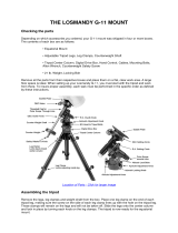
Figure 6c: OTA Rear View
4%
Position of Travel
Screw will vary by
OTA model

b Viewnder: 8x50, wide-eld sighting scope with
crosshairs that enables easy centering of objects
in the telescope eyepiece.
c Viewnder Collimation Screws: Adjust these
screws to align the viewnder. See page 23 for
more information.
d Eyepiece: Place the supplied HD-60 25mm
eyepiece into the 2” Star Diagonal with 1.25”
Adapter (Pg 18, Fig. 24) and tighten in place with
locking thumbscrew.
e SC Thread to 2” accessory adapter: The 2”
Diagonal Mirror is inserted into this adapter.
f 2” Adapter Thumbscrews: Tighten to secure the 2”
Diagonal in place.
g 2” Star Diagonal with 1.25” Adapter: Holds the
eyepiece upright for easy viewing. Provides a
more comfortable right-angle viewing position.
Slide the diagonal directly into the 2” Adapter and
tighten the thumbscrew to a rm feel only. See
page 18 for a photo and more information.
h 2-Speed Crayford Style Focusing Knobs: Moves
the telescope’s primary mirror in a nely-controlled
motion to achieve precise image focus. The
LX850 telescopes can be focused on objects from
a distance of about 200 ft to innity. Rotate the
focus knob clockwise to focus on distant object.
i AutoStar II Handbox: The LX850 user interface.
Use the Handbox to command the LX850 to
automatically slew to any object in the night sky.
See pages 27 thru 36 for a description of features.
j Handbox Holder: convenient place to place your
AutoStar II box. Keeps it at the ready.
1) Handbox Holder Tension Knob: Loosen to adjust
presentation angle – tighten to lock in place.
1! AutoStar II Coil Cord: Connects the handbox to
the Computer Control Panel via the HBX port.
1@ Telescope Control Panel:
A. ON/OFF Switch
B. 12v DC Power Connector
C. Electronic Focus Port
D. Illuminated Reticle Port
E. 12v DC Output
F. Handbox (HBX) Port
G. RS232 Port
H. StarLock Port
I. Aux Autoguider Port
1# Counterweight Safety Cap: Prevents the
counterweight from accidentally slipping off the
end of the counterweight shaft.
1$ Counterweight Shaft: Thread the counterweight
onto this shaft (below).
1% Counterweight: Counterbalances the weight of the
optical tube, and adds stability to the mount.
1^ Azimuth Lock Bolts. Once your LX850 is aligned
on the celestial pole, lock the azimuth bolts to
prevent movement in this direction.
1&
Latitude Adjustment Knob. Used to set the LX850
to the correct Latitude for your observing site.
1*
Latitude Lock Knob. Before using the Latitude
Adjustment Knob, loosen the Latitude Lock
Knob. Once the Latitude is adjusted, be sure to
lock this knob to prevent unwanted movement of
the LX850.
1(
RA Clutch: Tighten the three hex head screws
using the included 5/16” hex head tool to engage
the RA Drive.
2)
a. RA Drive: Precisely moves the telescope around
the RA Axis.
2)
b. RA Drive Cable: Connect the RA drive to the
Telescope Control Panel.
2!
DEC Drive Cable: Connects the DEC Motor to the
Compute Control Panel.
2@
DEC Drive Housing: Precisely moves the
telescope around the DEC Axis.
2#
DEC Clutch: Tighten the three hex head bolts
using the included 5/16” hex head tool to engage
the DEC Drive.
2$
a StarLock Narrow Field OTA: Narrow eld
optics that are used to precisely guide LX850
11
LX850 Key Features
LX850 Key Features

StarLock System.
2$
b StarLock Wideeld OTA: Used to orient the
LX850 in relation to the sky.
2%
a StarLock Connector Panel: Starlock cable
connection point and place where Starlock status
is displayed.
2%
b StarLock Connector Cable: 4-pin connector cable
plugs into StarLock.
2^
Optical Tube Assembly (OTA): The main optical
component that gathers the light from distant
objects and brings this light to a focus for
examination with the eyepiece.
2&
Dovetail Rail Safety Bolt: Make sure the Safety
knob is securely attached.
2*
StarLock Mount (Left side view): Attaches
StarLock to the telescope mount saddleplate.
2(
OTA Lock: Secures the OTA to the LX850 saddle
plate.
3)
Altitude Scale: Set the latitude of the
observing site on this scale using the latitude
adjustment knob.
3!
StarLock Locking Bolt: Secures the StarLock
assembly to the saddle plate.
3@
DEC Internal Cable Access Port: Loosen the two
thumbscrews, slide the door open to gain access
to the cable raceway that runs the length of the
DEC Axis.
3#
RA Internal Cable Access Port: Loosen the two
thumbscrews, slide the door open to gain access
to the cable raceway that runs the length of the RA
Axis.
3$
Azimuth Adjustment Knob: Once the Azimuth
Locking bolts are loose, make adjustments to the
mounts azimuth position aligning it to the celestial
pole. When properly adjusted, lock the Azimuth
Adjustment Lock bolts to prevent unwanted
Azimuth movement in the LX850.
3%
ACF Collimation Adjustment Screws: Use these 3
screws to ne tune your OTA’s optical alignment.
3^
StarLock Counterweight: Precisely counter
balance the StarLock assembly by moving
this weight. Remove if you mount StarLock directly
on the OTA.
3&
StarLock Counterweight Lock: Tighten to secure
the counterweight in place.
3*
GPS Sensor: Used to get precise date, time
and location of your observing site using global
positioning satellites.
3(
Dovetail Adapter Attachment Rails: The LX850
dovetail adapter is unique in that it will accept both
the Losmandy and Vixen style dovetails. Remove
and reverse the two surrounding dovetail rails so
the correct rail angle points toward the dovetail
size being used. Be sure to securely tighten the
rails. See page 9.
4)
LX850 Carry Handles: Use these carry handles
to help move the LX850 mount from one location
to another.
4!
Access Port Knob: Secures cover plates to RA
and DEC cable raceway.
4@
StarLock Telescope Connection: Connect
StarLock to the telescope control panel.
4#
Guider Status: LED indicates operation.
4$
RS-232 Port: Additional RS-232 port.
4%
Travel Screw: Firmly secures the primary mirror
in a xed position during travel protecting the
focusing mechanism from shock damage.
Remove this screw before attempting to focus the
telescope.
4^
Leg Lock: Locks leg extension in place.
4&
Spreader Bar: Rigidly holds legs open.
4*
Tension Knob: Tightens spreader bar to legs.
4(
Tension Hub: Locates extension arms.
5)
Extension arms: Locates tripod legs.
5!
Anti-Vibration Pad: reduces vibrations and
shortens damp-down time.
5@
Zero Image Shift Microfocuser for precision,
remote focusing.
AutoStar #497 HANDBOX
LX850 Key Features
12
LX850 Key Features

You may want to perform the assembly of the LX850
in the light of day to become familiar with the parts and
operation before performing observations on the night
sky. Setup the telescope in a large open area where
you can see lots of sky. Do not setup right next to a
building or a wall that will obstruct its view of the sky.
Make sure the ground is stable and is approximately
level. It is best to set up the scope away from bright
nighttime lighting, as bright lights will spoil your night
vision and impede your ability to see the sky.
The LX850 system includes the following:
• German Equatorial Mount Assembly with Dovetail
Saddle Plate
• StarLock Optical Tube and Sensor Assembly
• Counterweight(s)
• Counterweight Shaft with Safety Nut
• LX850 Field Tripod
• LX850 Accessories
• LX850 Control Panel
• Autostar II Hand Controller
• StarLock Cable
• StarLock Counterweight
• Custom Utility Tool
• 5/16” Hex head wrench
• DVD with AutoStar Suite and software
• #507 Connecting Cable with USB Adapter
• Internal Cable Fish Tool
• Anti-Vibration Pads
• Micro-focuser (ACF OTAs only)
Additionally, the LX850 can be ordered with various
OTAs and Accessories and may contain additional
counterweights and boxes depending on the
conguration ordered.
Assembly Tools
All of the tools necessary to assemble your LX850
telescope will be found in the accessory box:
• LX850 lock knob wrench: A dedicated tool for
securing small and large knobs on both the
telescope and tripod.
• 5/16” hex head wrench: Required for securing
DEC and RA clutches.
• Internal Cable Fish Tool: Assist routing StarLock,
DEC,RA and accessory connecting cables
Use of these tools will be described in the assembly
procedure. If you will be attaching an OTA that utilizes
a Vixen Style dovetail you will need a 3/16” hex head
wrench (included) to relocate the mounting rails on the
dovetail plate.
Tripod Assembly
Remove the LX850 eld tripod from the shipping
carton. Included in this carton is the spreader bar,
threaded rod (with spacer) and retaining clip; set these
aside. Position the tripod where you want the telescope
to be assembled. Stand the tripod vertically with the
tripod feet down and with the tripod still fully collapsed.
Grasp two of the tripod legs and, with the full weight
of the tripod on the third leg, gently pull the legs apart
to a fully open position. The legs should be spread so
the three leg braces are spaced evenly apart and the
tripod head is approximately level. Position one of the
legs so that it points approximately true South (True
North in the southern hemisphere). This will allow the
counterweight shaft to clear the tripod if used at low
latitudes.
Assembly
Fig 7: LX850 assembly tools.
Fig 8: Tripod.
Collapsed Opened
Leg points to
true South
LX850 Utility Tool
5/16" Hex Head Wrench
Internal Cable Fish Tool
13
Assembly

Loosen the two (2) leg lock-knobs on each tripod leg.
Adjust the height of the tripod to the desired height
and with the tripod head approximately level, tighten
the leg locks. Tighten the locks to a rm feel only; do
not over tighten.
Slide the threaded rod through the spreader and then
slide this assembly through the central mounting hole
in the tripod head. Place the threaded rod through
central mounting hole far enough so that the retaining
clip channel is exposed. Press t the retaining clip
through the machined channel. The retaining clip will
now hold the spreader bar for easy assembly.
Attach Mount Assembly to Tripod
Remove the equatorial mount assembly from the
shipping carton. You may notice as you are removing
the mount that the RA and DEC clutches are not
locked. This is intentionally done at the factory to
prevent possible damage to the gears while in transit.
Manually tighten down the three (3) RA and three
(3) DEC clutch lock bolts using the supplied 5/16”
hex head wrench to facilitate easier handling during
assembly. DO NOT OVERTIGHTEN.
Place the mount on the tripod head. At this point it is
advisable to either use one hand, or (ideally) enlist
someone else’s hand, to steady the mount while it is
fastened to the tripod.
Orient the mount so that it aligns with the poles, control
panel facing the South pole (North pole in the southern
hemisphere). Push the threaded rod up and secure
the mount to the tripod by tightening the central lock
knob. Use the supplied custom utility tool to secure it
to a “tight” t. If properly secured, the spreader bar will
make contact with all three tripod legs and the mount
will not slip.
Setting Latitude
Refer to the latitude chart on Appendix D, page 54.
Listed are the latitude for most major cites world wide.
Locate your city in the chart and note its latitude. If
your city is not listed follow the formula to calculate
your locations latitude.
Loosen the Attitude Adjustment Lock Knob (g. 18,
page 7). Locate the Attitude Adjustment Knob (g. 17,
page 7) and the Latitude Scale (g. 30, page 8). The
Fig 9: Mount in Box
Fig 11: Tighten Clutch.
Fig 12: Attach Counterweight Shaft.
Fig 10: DEC and RA Clutch Locations
DEC Clutch: Two of three
shown, third on opposite
side (not visible).
RA Clutch: Two of three
shown, third on opposite
side (not visible).
AutoStar #497 HANDBOX
Assembly
14

latitude scale has markings and a range that start at
zero (0) and ends at 70. Turn the Attitude Adjustment
Knob until the indicator points to your corresponding
latitude. Tighten the Attitude Adjustment Lock Knob.
Attach the Counterweight Shaft
Remove the counterweight shaft, with attached safety
nut, from its packaging. The safety nut is attached at
the factory for shipping. Removing the safety nut at
this time to lighten the counterweight shaft and make it
easier to attach on the DEC axis. Remove the retaining
nut by unscrewing it and set aside. Thread the shaft
into the receiver, making sure that the threads are
matching, not binding or cross threading.
Attach the Counterweight(s)
The counterweights are attached by threading them
onto the counterweight shaft to the desired position. If
the LX850 mount was purchased with a Meade optical
tube assembly (OTA), additional counterweights may
have been included depending on the OTA purchased.
Attach all counterweights that were included with the
mount. A good starting position for the counterweights is
to place them in the middle portion of the counterweight
shaft. When the mount is fully assembled with OTA
and accessories, the counterweights will be adjusted
to obtain a proper balance with the OTA. Note: 12”
and 14” f/8 ACF models please refer to Appendix F for
detailed counterweight instructions.
NOTE: WHEN ATTACHING THE COUNTER-
WEIGHT(S) TAKE CARE NOT TO DROP THEM
DURING ASSEMBLY AS THEY CAN CAUSE
SERIOUS INJURY, ESPECIALLY ON THE FOOT.
WHEN ATTACHING OR ADJUSTING THE POSITION
OF TWO (2) Counterweights PAY ATTENTION TO
THE POSITION OF YOUR HANDS SO NOT TO
PINCH THEM DURING ADJUSTMENT.
Screw the safety nut on then end of the shaft after the
counterweight(s) have been attached.
Routing Connector Cables Internally
Designed into the LX850 mount is a raceway that
routes cables through the body of the mount. Cables
connecting the RA, DEC motors and StarLock to the
control panel can be routed through this raceway,
eliminating worrisome “cable interference.” The
dedicated connecting cable(s) can be found in the
StarLock and/or the accessories box along with a
assisting cable routing tool. Cables for additional
equipment such as cameras can also be routed
through the internal raceway. Note: the StarLock
cable has been installed at the factory. Starlock’s 6-pin
connector connects to the control panel and the 4-pin
connector should be threaded through the hole in the
saddle plate and connected to the StarLock.
Fig 13: Attach Counterweight.
Fig 14: Remove left OTA dove tail mount.
Remove these four
fasteners to gain
access to dovetail
saddle plate fasteners.
Fig 15: Access to left saddle fastener revealed.
Remove these
fasteners to remove
dovetail saddle plate.
15
Assembly

Removing the Saddle
Your telescope mount shipped from the factory with the
OTA mount saddle attached. You will have to remove
it to gain access to the upper portion of the internal
raceway to nish routing any additional cables you
want to run to the OTA for cameras of other optional
equipment. Remove the StarLock counterweight by
loosening its retaining knob and sliding it off. Using a
3/16” hex-head wrench, loosen and remove the ve
(5) hex nuts that fastens the saddle to the mount Take
care when removing the fth (5th) and last fastener;
making sure to support the weight of the saddle as it
becomes free.
With the saddle removed, you are now ready to
route the cable(s) through the upper portion of the
internal raceway. The StarLock cable comes pre-
routed from the factory. If it has been removed or you
need to route additional cables from the OTA (eg.
Camera cables) follow these instructions.
StarLock Cable:
Important note: the StarLock cable is directional! Each
end has connectors with different congurations; each
connector conguration must be correctly oriented
so that it will plug into its corresponding receptacle.
The four-pin connector is inserted into the four-pin
receptacle on the back of the StarLock. The six-pin
connector is plugged into the six-pin receptacle on the
mount control panel labeled “StarLock”. Please note
the correct cable orientation before beginning to route
the cable(s).
Begin by passing the four-pin connector thru the side
passway in the DEC housing below the OTA saddle
(Page 8 and 9, g 2 and 3). This four-pin connector
will plug-in to the receptacle on the back of StarLock.
Pass the cable end with the six-pins down the DEC
shaft. Open the access port at the front of the RA axis
and as the six (6) end feeds down grasp and pull it out,
taking care not to pull the four-pin connector through
the side passway in the DEC housing. Then feed the
six-pin end down the RA shaft toward the DEC access
door (Page 8, Fig 32). Slide open the cable access
port door by loosing the two knurled knobs (Page 9,
Fig 41). Observing through this port, and feeding the
six-pin cable through, grasp it as it comes through
the port. Again, take up the excess cable. This six-pin
Fig 18: Pulling cable out to connect to control panel.
Fig 17: Routing cable under the saddle plate.
Direction of Cable
Fig 19: Route of cable from StarLock module
AutoStar #497 HANDBOX
Assembly
16
Fig 16: Access to the cable raceway.

connector is now ready to be inserted into the RS232
receptacle on the control panel labeled “StarLock.”
At this point you will need to reattach the Optical Tube
Saddle Plate. Reverse the steps outlined in the step
“Removing the Saddle” above.
Attach the Control Module
Take the control panel module out of the box that
contained the mount, and slide it on the mounting
rail at the rear end of the RA housing. Loosen the
two knurled set-screw knobs on the bottom side of
the control module and slide it on the rail, tightening
the same set-screw knobs. Insert the StarLock six-
pin connector into the receptacle labeled “StarLock”
(Page 10, Fig. 6a, H).
DEC and RA Connecting Cables
The connecting cables for the RA & DEC are attached
to the control panel module and can not be removed
from the module. The short cable connects directly
to the RA gearbox that is directly above the module.
Insert the DIN connector, observing and aligning the
orientation of the pins to match. Once the pins are
seated, secure by screwing the dedicated retaining
collar until rm (Fig. 21). The longer cable connects
to the DEC gearbox and will need to be threaded
through the access port on the RA axis, directly above
the module (Fig. 20). Using the cable pull tool feed
the cable through the raceway, watch for it through
the access port on the front of the RA axis (Fig. 21).
Grasp it as it comes within reach, and feed through the
excess cable. Once it has been fed through, insert and
secure the connector to the DEC drive directly above
the access port (Page 8, #21). Once the pins are
seated, secure by screwing the dedicated retaining
collar until rm.
Attach the Optical Tube
Assembly (OTA)
Note that there are two options for orientating the
dovetail rail and its location. As shipped from the
factory, dovetail rails are congured to receive a
standard Losmandy®-style dovetail. Meade LX850
OTAs are shipped with their dedicated dovetail plates
pre-attached to the tube. Depending on your OTA’s
Fig 22: Replace the saddle plate
Fig 23: Slide the OTA dovetail into the saddle plate
Fig 20: Connecting motor to control module.
Note Rail to attach
Telescope Control Module
17
Assembly
Note: Locking
collar
Fig 21: DIN Style Connector
NOTE: Remove the travel screw before attempting to focus the OTA. Failure to do so may result in damage
to the Crayford focusing mechanism.

dovetail, you may need to relocate both sides of the
dovetail receiver rails (Page 9, Fig. 5).
• OTAs with a Losmandy®-Style Dovetail: All
Meade LX850, Advanced Coma-Free Optical
tubes utilize the standard Losmandy®-style
dovetail plate. To prepare the LX850 Dovetail
adapter to accept the Losmandy dovetail plate,
the mounting rails on the dovetail adapter must
be positioned in the correct location and with the
correct long side of the rail facing inward toward
its corresponding mounting rail. If you look at each
long side of the rail, you will notice the draft angle is
different on each side (Page 9, Fig 5). Make sure
the correct angled side is used on both rails before
attaching the OTA. Both rails should be secured
rmly to the dovetail adapter before an OTA
is attached.
• NOTE: Due to its weight and size, it is advisable
that the 12” & 14” Advanced Coma-Free OTAs be
mounted by two (2) people.
• OTAs with a Vixen®-style dovetail: All Meade
LX850 refractors utilize a standard Vixen®-style
dovetail plate. To congure the dovetail adapter to
accept this dovetail plate, orient the adapter rails
so that the narrow draft angle is facing inward
as shown (Page 9, Fig. 5). Position the inner
rail so that it will mate with the narrowest set of
mounting points.
NOTE: Before attaching an OTA to the mount, make
sure the clutches on each axis are locked so the mount
does not shift during OTA installation and the proper
number of counterweights are attached.
The saddle plate is pointing straight up the RA axis
with StarLock dovetail mounting position on the left
side when viewed from behind the mount.
To attach an OTA, rmly grasp the OTA, remove from
the shipping box, and slide the dovetail plate into the
dovetail adapter. Maintaining a rm grip on the OTA,
tighten the two (2) lock-bolts on the dovetail adapter
to a “rm” feel.
Attach Diagonal and Eyepiece
Remove the dust cap from the rear cell of
the telescope.
• Meade Advanced Coma-Free OTAs: If your
telescope was shipped with Meade's #1209 Zero
Image Shift Microfocuser please refer to the
detailed instructions that were included.
• Meade Refractors: Slide the diagonal mirror
into the focuser and lock in place by turning the
thumbscrew(s) to a rm feel. Remove the Meade
eyepiece from its container and place it in the
diagonal mirror. Tighten the thumbscrew(s) to a
rm feel only.
Attach StarLock Assembly
StarLock’s default mounting location is on the saddle
plate. The 10”, 12” and 14” ACF models feature a
second mounting location at the top-rear of the optical
tube assembly. Due to the longer focal length of the
ACF optics, this second, top of the OTA mounting
point, is preferred for these telescopes, as it minimizes
any differential exure.
Locate and unpack the StarLock assembly. The
dovetail adapter and its dedicated counterweight are
pre-installed at the factory and are correctly congured
for use in the Northern Hemisphere. For use in the
Northern Hemisphere, the StarLock assembly is
attached to the dovetail adapter on the left side of the
Fig 24: Diagonal and eyepiece in place
AutoStar #497 HANDBOX
Assembly
18
Fig 25: StarLock mounted on ACF OTA
NOTE: Remove the travel screw before attempting to focus the OTA. Failure to do so may result in damage
to the Crayford focusing mechanism.

OTA. To install StarLock, loosen the two (2) retaining
nuts at the side of dovetail adapter, slip in the StarLock
assembly, position Starlock so that the back edge of
the StarLock dovetail is ush with the lower edge of
the saddle plate. Tighten to securely retain StarLock
(Page 8, Fig. 42). Locate the included rectangular
counterweight, loosen its securing thumbscrew, and
slide it on the rail on the opposite side of the dovetail
adapter (if needed). Note that the counterweight is
NOT needed when StarLock is mounted to a LX850
ACF OTA. Use the counterweight when StarLock
is mounted directly to the saddle plate. Secure the
counterweight by re-tightening the nuts.
Attach the four-pin StarLock connector cable to the
rear panel of StarLock in the receptacle on the left side
(Page 10, Fig. 42).
Plug in the AutoStar II Handbox
Locate and unpack the AutoStar II handbox. The
connecting cable is packed together with the handbox.
Plug one connector into the handbox, and the other
into the “HBX” receptacle on the control module.
Fig 26: Mounting StarLock to the saddle plate. Attach
StarLock counterweight.
Attach the Viewnder to the OTA
The Meade OTAs sold with the LX850 are equipped
with a standard 8x50 nderscope. To assemble and
align the viewnder, perform steps 1 through 6 below
during the daytime.
1. Assemble the viewnder by attaching all included
thumbscrews onto the viewnder bracket and
insert the 8X50 viewnder into the bracket. Tighten
the thumbscrews to a rm feel only so the 8x50
optical tube is roughly centered in the middle of
the bracket.
2 . Slide the viewnder bracket into its mounting
assembly on the OTA (Page 7, Fig. 1, #1). To secure
the viewnder to the mounting assembly, tighten
the two thumbscrews (Page 7, Fig. 1, #2) to a rm
feel only.
Mount Additional Accessories and
Equipment
At this time it is advisable to mount any additional
accessories and equipment that you will be using
during nighttime use. Balancing the telescope is the
next step and it is important that this procedure be
performed in its operational conguration.
Balancing the Telescope
Level the mount, using the integrated bubble level
at the base of the mount as an aide if necessary, by
adjusting the length of the three tripod legs.
Before using the telescope, you will need to balance the
RA/DEC axes and the StarLock. Before you balance,
attach the eyepiece assembly, the viewnder and all
the accessories you will be using with the telescope
(cameras, guide scopes, etc.). In other words, you
need to balance the unit with all the “weight” that will
be attached to it.
Fig 28: Slide viewnder into receiver
19
Assembly
Fig 27: Connect handbox cable to HBX

To balance the telescope, unlock the Right Ascension
or RA clutches (3-Places, Page 14, Fig. 10). When
this axis is unlocked, the telescope pivots on the RA
axis. Later in the procedure, you will also unlock the
Declination or DEC clutches (3-Places, Page 14, Fig.
10). When unlocked, it pivots on the DEC axis. Try to
become familiar with these locks and observe how
the telescope moves on each axis. To obtain a ne
balance of the telescope, follow the method below:
Balancing the RA Axis
1. Firmly hold the optical tube secure so that it cannot
accidentally swing freely. NOTE: An unbalanced
OTA can swing quickly causing injury to the user.
Loosen the RA Clutch. The optical tube now moves
freely about the RA axis. Rotate the telescope so
that the counterweight shaft (Page 20, Fig. 29) is
parallel (horizontal) to the ground.
2. Rotate the counterweight along the counterweight
shaft until the telescope remains in the horizontal
position without moving in either direction. Now
push the RA shaft from the end up and down.
Adjust the counterweight position until it takes the
same force to move the RA shaft up and down.
Balancing the DEC Axis
Again, hold the optical tube so that it cannot accidentally
swing freely. NOTE: An unbalanced OTA can swing
quickly causing injury to the user. Position the RA axis
parallel to the ground and tighten the RA locks. Unlock
the DEC Clutches. The telescope now is able to move
freely about the DEC axes. Position the OTA parallel
to the ground.
Advanced Coma-Free OTAs: Slightly loosen the OTA
dovetail adapter lock knobs (Page 8, Fig. 29) so that
the tube assembly slides easily back and forth in the
dovetail mount. Be careful that the OTA does not fall
out of the dovetail adapter! Start with 1/2" of the OTA
dovetail plate extended out of the DEC Saddle (See
Appendix F, pg 56). Move the OTA assembly fore or
aft, in the dovetail adapter until the telescope remains
in horizontal position without tending to drift down in
either direction. Once this is achieved tighten the OTA
dovetail lock knobs rmly.
Meade Refractors: Slightly loosen the cradle ring lock
knobs so that the main tube slides easily back and
forth in the cradle rings. Move the main tube in the
cradle rings until the telescope remains in one position
without tending to drift down in either direction. Once
this is achieved tighten the cradle ring lock knobs. If
the refractor is equipped with a dew shield, make sure
it is fully extended prior to balancing.
Balancing the StarLock
When the StarLock is mounted on the saddleplate
it is mounted off-center from the DEC axis, it must
be properly counter-balanced to achieve optimum
performance. With the DEC axis lock still loose and with
the RA axis parallel to the ground, rotate the OTA so
that points directly upward (Fig. 31). Start by loosening
and moving the rectangular StarLock counterweight
so there is a 1/2" gap between the weight and the DEC
Saddle plate screws (See Appendix F). Move the
weight until the telescope remains pointing upward,
without tending drift in either direction. Once this is
achieved tighten the StarLock counterweight knob and
re-lock the DEC clutches.
The telescope is now properly balanced. Return the
LX850 to the original position with the counterweight
shaft pointed to the ground and OTA pointed
straight ahead.
Fig 29: Balancing the RA axes
Move Counterweight
To Achieve RA Balance
RA Axis
Assembly
Assembly
20
Slide the OTA to
achieve balance
Fig 30: Balancing the DEC axes
/