Page is loading ...

2
14136172.03 11/2019 EN/DE/FR/ES
WIKA operating instructions OEM pressure sensor, model MH-3
EN
DE
FR
ES
© 08/2015 WIKA Alexander Wiegand SE & Co. KG
All rights reserved. / Alle Rechte vorbehalten.
WIKA
®
is a registered trademark in various countries.
WIKA
®
ist eine geschützte Marke in verschiedenen Ländern.
Prior to starting any work, read the operating instructions!
Keep for later use!
Vor Beginn aller Arbeiten Betriebsanleitung lesen!
Zum späteren Gebrauch aufbewahren!
Lire le mode d‘emploi avant de commencer toute opération !
A conserver pour une utilisation ultérieure !
¡Leer el manual de instrucciones antes de comenzar cualquier trabajo!
¡Guardar el manual para una eventual consulta!
Betriebsanleitung Typ MH-3
Seite 23 - 42
Operating instructions model MH-3
Page 3 - 22
Manual de instrucciones modelo
MH-3 Página 63 - 82
Mode d‘emploi
type MH-3 Page 43 - 62

3WIKA operating instructions, OEM pressure sensor, model MH-3
EN
14136172.03 11/2019 EN/DE/FR/ES
Contents
1. General information 4
2. Design and function 5
3. Safety 6
4. Transport, packaging and storage 8
5. Commissioning, operation 9
6. Faults 11
7. Maintenance and cleaning 12
8. Dismounting, return and disposal 13
9. Specifications 15
Declarations of conformity can be found online at www.wika.com
Contents

4
WIKA operating instructions, OEM pressure sensor, model MH-3
14136172.03 11/2019 EN/DE/FR/ES
EN
1. General information
1. General information
■
The instrument described in the operating instructions has been designed and
manufactured using state-of-the-art technology. All components are subject to strin-
gent quality and environmental criteria during production. Our management systems
are certified to ISO 9001 and ISO 14001.
■
These operating instructions contain important information on handling the instru-
ment. Working safely requires that all safety instructions and work instructions are
observed.
■
Observe the relevant local accident prevention regulations and general safety regula-
tions for the instrument's range of use.
■
The operating instructions are part of the product and must be kept in the immediate
vicinity of the instrument and readily accessible to skilled personnel at any time. Pass
the operating instructions on to the next operator or owner of the instrument.
■
Skilled personnel must have carefully read and understood the operating instructions
prior to beginning any work.
■
The general terms and conditions contained in the sales documentation shall apply.
■
Subject to technical modifications.
■
Further information:
- Internet address: www.wika.de / www.wika.com
- Relevant data sheet: PE 81.59
- Application consultant:
Tel.: +49 9372 132-0
Fax: +49 9372 132-406
info@wika.com

5WIKA operating instructions, OEM pressure sensor, model MH-3
EN
14136172.03 11/2019 EN/DE/FR/ES
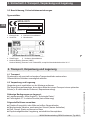
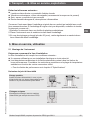
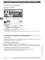
2. Design and function
2. Design and function
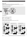
2.1 Overview
2.2 Signal clamping (not for MH-3-HY)
The output signal of a pressure sensor can be above the nominal maximum signal
value, if no signal clamping has been set. Likewise, the output signal can also be below
the nominal minimum signal value. This undefined condition can cause an error in
the machine (software) of the customer. Signal clamping limits the output signal to a
minimum or maximum value which is to be defined by the customer.
2.3 Diagnostic function
By means of the output signal, fault conditions can be detected and evaluated via
software. Thus it is possible to differentiate between permanent and temporary faults.
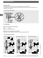
2.4 CDS system
All process connections are available with the CDS system. The diameter of the pressu-
re port is reduced in order to counteract pressure spikes and cavitation.
2.5 Scope of delivery
■
Pressure sensor
■
Operating instructions (for model MH-3-HY)
Cross-check scope of delivery with delivery note.
Electrical connection (depending on version)
Case
Process connection, spanner flats
Process connection, thread

6
WIKA operating instructions, OEM pressure sensor, model MH-3
14136172.03 11/2019 EN/DE/FR/ES
EN
3. Safety
3. Safety
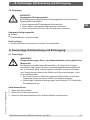
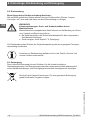
3.1 Explanation of symbols
WARNING!
... indicates a potentially dangerous situation that can result in serious
injury or death, if not avoided.
CAUTION!
... indicates a potentially dangerous situation that can result in light
injuries or damage to property or the environment, if not avoided.
Information
... points out useful tips, recommendations and information for efficient
and trouble-free operation.
3.2 Intended use
The pressure sensor is used for measuring pressure. The measured pressure is output
as an electrical signal.
The pressure sensor model MH-3 is intended for use in mobile working machines.
The MH-3-HY pressure sensor for mobile hydrogen applications is typically used to
monitor tank pressure and the pressure after the reducing valve in hydrogen-powered
vehicles, especially industrial trucks, utility/municipal vehicles and buses. The exact
position of the sensor is therefore dependent upon the customer and application.
Only use the pressure sensor in applications that lie within its technical performance
limits (e.g. max. ambient temperature, material compatibility, ...).
→ For performance limits see chapter 9 “Specifications”.
The instrument has been designed and built solely for the intended use described here,
and may only be used accordingly.
The manufacturer shall not be liable for claims of any type based on operation contrary
to the intended use.
Technical restrictions
■
Any permanent operation in the overload range is not permitted. Above the operating
pressure, up to the overload limit, the pressure sensor is operating outside its speci-
fication. The overload limit is intended to prevent damage to the pressure sensor, as
part of a pressure vessel system, during the pressure containment test.
■
The overload limit must never be exceeded, even when failures occur in the end-use
application. Loads above the overload limit can cause irreversible damage, which can
lead, for example, to permanent measuring errors.

7WIKA operating instructions, OEM pressure sensor, model MH-3
EN
14136172.03 11/2019 EN/DE/FR/ES
3. Safety
Specific notes based on the medium hydrogen (model MH-3-HY)
The sensor offered uses the wetted materials 2.4711 and 1.4404. These materials are
resistant to hydrogen embrittlement.
With a temperature of up to 30 °C, the stability under hydrogen influence is typically
1 %/year, maximum 3 %/year.
Due to hydrogen diffusion into the sensor structures, a signal drift can occur dependent
upon the time. The time until the occurrence of a relevant signal drift and the size of the
signal drift depends mainly on factors such as the temperature of the hydrogen, hydro-
gen content in the medium, and the diaphragm thickness of the pressure sensor used.
It is explicitly recommended for the user to test the selected product version for suitabili-
ty in the intended application(s) with the specified ambient conditions.
3.3 Personnel qualification
Skilled personnel
Skilled personnel, authorised by the operator, are understood to be personnel who,
based on their technical training, knowledge of measurement and control technolo-
gy and on their experience and knowledge of country-specific regulations, current
standards and directives, are capable of carrying out the work described and indepen-
dently recognising potential hazards.
3.4 Personal protective equipment
The personal protective equipment is designed to protect the skilled personnel from
hazards that could impair their safety or health during work. When carrying out the
various tasks on and with the instrument, the skilled personnel must wear personal
protective equipment.
Follow the instructions displayed in the work area regarding personal protective
equipment!
The requisite personal protective equipment must be provided by the operating company.

8
WIKA operating instructions, OEM pressure sensor, model MH-3
14136172.03 11/2019 EN/DE/FR/ES
EN
3. Safety/4. Transport, packaging and storage
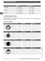
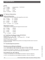
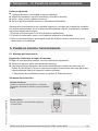
3.5 Labelling, safety marks
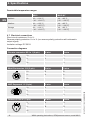
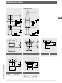
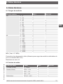
Product labels
1 Product no. 3 Coded date of manufacture
2 Serial no. 4 Measuring range
1 Product no. 4 Specifications
2 Approvals 5 Coded date of manufacture
3 Nominal working pressure (NWP)
The nominal working pressure per 79/2009/EC corresponds to a nominal working pressure at 15 °C
4. Transport, packaging and storage
4.1 Transport
Check the pressure sensor for any damage that may have been caused by transport.
Obvious damage must be reported immediately.
4.2 Packaging and storage
Do not remove packaging until just before mounting.
Keep the packaging as it will provide optimum protection during transport (e.g. change
in installation site, sending for repair).
Permissible conditions at the place of storage:
■
Storage temperature see chapter 9 “Specifications”
■
Humidity: 67 % relative humidity (no condensation)
Avoid exposure to the following factors:
■
Direct sunlight or proximity to hot objects
■
Mechanical vibration, mechanical shock (putting it down hard)
■
Soot, vapour, dust and corrosive gases
■
Hazardous environments, flammable atmospheres
5
wika.com
MH-3
MH-3-HY
Made in Germany
WIKA Alexander Wiegand SE & Co. KG; 63911 Klingenberg
E₁
e 1
1
2 2
3
4
4
5
1
2
3
4
2

9WIKA operating instructions, OEM pressure sensor, model MH-3
EN
14136172.03 11/2019 EN/DE/FR/ES
4.Transport, .../5. Commissioning, operation
Store the instrument in its original packaging in a location that fulfils the conditions
listed above. If the original packaging is not available, pack and store the instrument as
described below:
1. Wrap the instrument in an antistatic plastic film.
2. Place the instrument, along with shock-absorbent material, in the packaging.
3. If stored for a prolonged period of time (more than 30 days), place a bag containing a
desiccant inside the packaging.
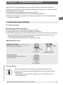
5. Commissioning, operation
5.1 Mounting the instrument
Requirements for mounting point
The mounting point must meet the following conditions:
■
Sufficient space for a safe electrical installation.
■
Permissible ambient and medium temperatures remain within the performance limits.
Consider possible restrictions on the ambient temperature range caused by mating
connector used.
→ For performance limits see chapter 9 “Specifications”
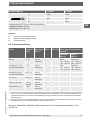
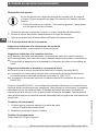
Sealing variants
Parallel threads
Seal the sealing face with flat gasket, lens-type
sealing ring or WIKA profile sealing.
per EN 837
per ISO 1179-2
(formerly DIN 3852-E)
Tapered threads
Wrap threads with sealing material
(e.g. PTFE tape).
NPT, R and PT

10
WIKA operating instructions, OEM pressure sensor, model MH-3
14136172.03 11/2019 EN/DE/FR/ES
EN
Mounting the instrument
The max. torque depends on the mounting point (e.g. material and shape).
If you have any questions, please contact our application consultant.
→ For contact details see chapter 1 “General information” or the back
page of the operating instructions.
1. Seal the sealing face (→ see “Sealing variants”).
2
.
At the mounting point, screw the pressure sensor in hand-tight.
3
.
Tighten with a torque spanner using the spanner flats.
5.2 Connecting the instrument to the electric system
Requirements for voltage supply
Supply voltage see chapter 9 „Specifications“.
Requirements for electrical connection
■
Cable diameter matches the cable bushing of the mating connector.
■
Cable gland and seals of the mating connector are correctly seated.
■
With cable outlets, no humidity can ingress at the cable end.
Requirement for shielding and grounding
■
The pressure sensor must be grounded via the process connection (model MH-3).
■
The connection is made in the vehicle with a suitable power supply/control unit that
complies with regulation 10. (MH-3-HY).
■
The connection to vehicle ground is made via the process connection (MH-3-HY).
In accordance with EN 61326-1, in case of outdoor installations, faults caused by surge
voltages must be considered. To protect the instrument, it must be connected using
a shielded cable. The shield of the cable must be connected on at least one side to
ground or a suitable reference potential. Optionally, a suitable external measure can be
taken to ensure protection against surge voltages.
Connecting the instrument
1. Assemble the mating connector or cable outlet.
→ See “Pin assignments”
2
.
Establish the plug connection.
Pin assignments
See chapter 9 “Specifications”.
5. Commissioning, operation

11WIKA operating instructions, OEM pressure sensor, model MH-3
EN
14136172.03 11/2019 EN/DE/FR/ES
6. Faults
CAUTION!
Physical injuries and damage to property and the environment
If faults cannot be eliminated by means of the listed measures, the
pressure sensor must be taken out of operation immediately.
▶
Ensure that pressure or signal is no longer present and protect against
accidental commissioning.
▶
Contact the manufacturer.
▶
If a return is needed, please follow the instructions given in chapter 8.2
“Return”.
WARNING!
Physical injuries and damage to property and the environment
caused by hazardous media
Upon contact with hazardous media (e.g. oxygen, acetylene, flammable
or toxic substances), harmful media (e.g. corrosive, toxic, carcinogenic,
radioactive), and also with refrigeration plants and compressors, there is a
danger of physical injuries and damage to property and the environment.
▶
Should a failure occur, aggressive media with extremely high tempe-
rature and under high pressure or vacuum may be present at the
instrument.
▶
For these media, in addition to all standard regulations, the appropriate
existing codes or regulations must also be followed.
▶
Wear the requisite protective equipment (see chapter 3.4 “Personal
protective equipment”).
For contact details see chapter 1 “General information” or the back page
of the operating instructions.
Faults Causes Measures
Plastic has faded UV irradiation No measures required
Discolouration is harmless
No output signal Cable break Check the continuity, and if
necessary exchange the cable
No/wrong supply voltage Rectify the supply voltage
No/wrong output signal
Wiring error Rectify the wiring
Constant output signal upon
change in pressure
Mechanical overload caused
by overpressure
Replace instrument; if it
fails repeatedly, contact the
manufacturer.
6. Faults

12
WIKA operating instructions, OEM pressure sensor, model MH-3
14136172.03 11/2019 EN/DE/FR/ES
EN
6. Faults/7. Maintenance and cleaning
Faults Causes Measures
Signal span too small/drops Mechanical overload caused
by overpressure
Replace instrument; if it
fails repeatedly, contact the
manufacturer.
Diaphragm damaged, e.g. due
to impacts, abrasive/aggres-
sive medium; corrosion at
diaphragm or process connec-
tion; transmission medium
missing
Replace instrument; if it
fails repeatedly, contact the
manufacturer.
Sealing/sealing face damaged
or soiled, sealing does not
have a tight fit, threads jammed
Clean the sealing/sealing face,
replace sealing if applicable
Signal span varies/inaccurate
EMC interference sources in
the environment; e.g. frequency
converter
Shield instrument; cable shield;
remove source of interference
Operating temperature too
high/low
Lower/increase the tempera-
ture
Instrument not grounded Ground the instrument
Strongly fluctuating pressure of
the process medium
Dampening; consulting by the
manufacturer
Deviating zero point signal Operating temperature too
high/low
Lower/increase the tempera-
ture
Other mounting position Adjust the zero point
Overpressure limit exceeded Reduce the pressure
If complaint is unjustified, we will charge you the complaint processing fees.
7. Maintenance and cleaning
7.1 Maintenance
This pressure sensor is maintenance-free.
Repairs must only be carried out by the manufacturer.
Regular inspection of the sealing by the operator is necessary.

13WIKA operating instructions, OEM pressure sensor, model MH-3
EN
14136172.03 11/2019 EN/DE/FR/ES
7. .../8. Dismounting, return and disposal
7.2 Cleaning
CAUTION!
Unsuitable cleaning agents
Cleaning with unsuitable cleaning agents may damage the instrument and
the product label.
▶
Do not use any aggressive cleaning agents.
▶
Do not use any hard or pointed objects.
▶
Do not use any abrasive cloths or sponges.
Suitable cleaning agents
■
Water
■
Conventional dishwashing detergent
Cleaning the instrument
▶
Wipe the instrument surface using a soft, damp cloth.
8. Dismounting, return and disposal
8.1 Dismounting
WARNING!
Physical injuries and damage to property and the environment
caused by hazardous media
Upon contact with hazardous media (e.g. oxygen, acetylene, flammable
or toxic substances), harmful media (e.g. corrosive, toxic, carcinogenic,
radioactive), and also with refrigeration plants and compressors, there
is a danger of physical injuries and damage to property and the environ-
ment.
▶
Should a failure occur, aggressive media with extremely high tempe-
rature and under high pressure or vacuum may be present at the
instrument.
▶
Wear the requisite protective equipment (see chapter 3.4 “Personal
protective equipment”).
Dismounting the instrument
1. Disconnect the instrument from the mains.
2
.
Disconnect the electrical connection.
3
.
Unscrew the instrument with a spanner using the spanner flats.

14
WIKA operating instructions, OEM pressure sensor, model MH-3
14136172.03 11/2019 EN/DE/FR/ES
EN
8. Dismounting, return and disposal
8.2 Return
Strictly observe the following when shipping the instrument:
All instruments delivered to WIKA must be free from any kind of hazardous substances
(acids, bases, solutions, etc.) and must therefore be cleaned before being returned.
WARNING!
Physical injuries and damage to property and the environment
through residual media
Residual media in the dismounted instrument can result in a risk to
persons, the environment and equipment.
▶
With hazardous substances, include the material safety data sheet for
the corresponding medium.
▶
Clean the instrument, see chapter 7.2 “Cleaning”.
When returning the instrument, use the original packaging or a suitable transport
packaging.
Information on returns can be found under the heading “Service” on our
local website.
8.3 Disposal
Incorrect disposal can put the environment at risk.
Dispose of instrument components and packaging materials in an environmentally
compatible way and in accordance with the country-specific waste disposal regulations.
Do not dispose of with household waste. Ensure a proper disposal in
accordance with national regulations.

15WIKA operating instructions, OEM pressure sensor, model MH-3
EN
14136172.03 11/2019 EN/DE/FR/ES
9. Specifications
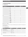
9.1 Measuring ranges
Gauge pressure MH-3 MH-3-HY
bar 0 ... 6 x -
0 ... 10 x -
0 ... 16 x -
0 ... 20 - x
0 ... 25 x x
0 ... 40 x x
0 ... 60 x x
0 ... 100 x x
0 ... 160 x x
0 ... 250 x x
0 ... 400 x x
0 ... 600 x x
psi 0 … 100 x -
0 … 160 x -
0 … 200 x -
0 ... 300 x x
0 ... 500 x x
0 ... 1,000 x x
0 ... 1,500 x x
0 ... 2,000 x x
0 ... 3,000 x x
0 ... 5,000 x x
0 ... 8,000 x x
MPa (1 bar = 0.1 MPa)
Overload safety: 2 times (deviating for individual psi measuring ranges of model
MH-3-HY)
Vacuum tightness: Yes
9.2 Output signals
Signal type Signal MH-3 MH-3-HY
Current (2-wire) 4 ... 20 mA x x
Voltage (3-wire) DC 0 ... 10 V x -
DC 1 ... 5 V x -
DC 1 ... 6 V x -
Ratiometric DC 0.5 ... 4.5 V x x
9. Specifications

16
WIKA operating instructions, OEM pressure sensor, model MH-3
14136172.03 11/2019 EN/DE/FR/ES
EN
Load
■
4 ... 20 mA: ≤ (power supply - 10 V)/0.02 A
■
DC 0 ... 10 V: > 5 kΩ
■
DC 1 ... 5 V: > 2.5 kΩ
■
DC 1 ... 6 V: > 5 kΩ
■
DC 0.5 ... 4.5 V: > 4.5 kΩ
9.3 Voltage supply
Supply voltage
The power supply depends on the selected output signal.
■
4 ... 20 mA: DC 10 ... 36 V
■
DC 0 ... 10 V: DC 14 ... 36 V
■
DC 1 ... 5 V: DC 8 ... 36 V
■
DC 1 ... 6 V: DC 9 ... 36 V
■
DC 0.5 ... 4.5 V: DC 4.5 ... 5.5 V
Current supply
The current supply depends on the selected output signal.
■
4 ... 20 mA < 30 mA
■
DC 0 ... 10 V < 10 mA
■
DC 1 ... 5 V < 10 mA
■
DC 1 ... 6 V < 10 mA
■
DC 0.5 ... 4.5 V < 10 mA
9.4 Reference conditions (per IEC 61298-1)
Temperature: 15 ... 25 °C [59 ... 77 °F]
Atmospheric pressure: 860 ... 1,060 mbar [12.5 ... 15.4 psi]
Air humidity: 45 ... 75 % r. h.
Supply voltage: DC 24 V
Mounting position: Calibrated in vertical mounting position with pressure connection
facing downwards.
9.5 Accuracy specifications
Accuracy at reference conditions
≤ ±1 % of span for measuring ranges ≥ 40 bar [≥ 500 psi]
≤ ±2 % of span for measuring ranges < 40 bar [< 500 psi]
Including non-linearity, hysteresis, zero offset and end value deviation (corresponds to
measured error per IEC 61298-2).
Non-linearity (per IEC 61298-2)
≤ ±0.25 % of span for measuring ranges ≥ 40 bar [≥ 500 psi]
≤ ±0.40 % of span for measuring ranges < 40 bar [< 500 psi]
9. Specifications

17WIKA operating instructions, OEM pressure sensor, model MH-3
EN
14136172.03 11/2019 EN/DE/FR/ES
9. Specifications
Temperature error at -40 ... +100 °C [-40 ... +212 °F]
Mean temperature coefficient of zero point:
≤ ±0.15 % of span/10 K for measuring ranges ≥ 40 bar [≥ 500 psi]
For measuring ranges < 40 bar [< 500 psi]: On request
Mean temperature coefficient of span: ≤ ±0.08 % of span/10 K
Settling time
≤ 2 ms
Long-term stability
≤ ±0.2 % of span/year for measuring ranges ≥ 40 bar [≥ 500 psi]
≤ ±0.3 % of span/year for measuring ranges < 40 bar [< 500 psi]
For model MH-3-HY:
Medium temperature range -40 ... +30 °C [-40 ... +86 °F]:
typ. ≤ ±1 %/max. ≤ ±3 % of span/year
It is explicitly recommended for the user to test the selected product version for suitabili-
ty in the intended application(s) with the specified ambient conditions.
9.6 Operating conditions
Ingress protection (per IEC 60529)
The ingress protection depends on the type of electrical connection.
Electrical connection Ingress protection
1)
MH-3 MH-3-HY
Deutsch DT04-3P (3-pin) IP67 x
Delphi connector Metri-Pack
series 150, 3-pin
IP67 x x
Circular connector M12 x 1 (4-pin) IP67 x
AMP Superseal connector 1.5 series,
3-pin
IP67 x x
Cable outlet (0.5/1/2.5 m), 2-pin IP6K9K x
Cable outlet (0.5/1/2.5 m), 3-pin IP6K9K x
1) The stated ingress protection only applies when plugged in using mating connectors that have the appropria-
te ingress protection.
Vibration resistance
20 g (per IEC 60068-2-6)
Shock resistance
500 g (per IEC 60068-2-27)

18
WIKA operating instructions, OEM pressure sensor, model MH-3
14136172.03 11/2019 EN/DE/FR/ES
EN
Permissible temperature ranges
MH-3 MH-3-HY
Ambient -40 ... +100 °C
[-40 ... +212 °F]
-40 ... +85 °C
[-40 ... +185 °F]
Medium -40 ... +125 °C
[-40 ... +257 °F]
-40 ... +85 °C
[-40 ... +185 °F]
Storage -40 ... +100 °C
[-40 ... +212 °F]
-40 ... +85 °C
[-40 ... +185 °F]
9.7 Electrical connections
Short-circuit resistance: S
+
to U
-
Reverse polarity protection: U+ to U- (no reverse polarity protection with ratiometric
output signal)
Insulation voltage: DC 500 V
Connection diagrams
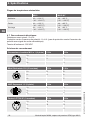
Circular connector M12 x 1 (4-pin) 2-wire 3-wire
U
+
1 1
U
-
3 3
S
+
- 4
Metri-Pack series 150 (3-pin) 2-wire 3-wire
U
+
B B
U
-
A A
S
+
- C
AMP Superseal 1.5 (3-pin) 2-wire 3-wire
U
+
3 3
U
-
1 1
S
+
- 2
Deutsch DT04-3P (3-pin) 2-wire 3-wire
U
+
A A
U
-
B B
S
+
- C
9. Specifications

19WIKA operating instructions, OEM pressure sensor, model MH-3
EN
14136172.03 11/2019 EN/DE/FR/ES
Cable outlet 2-wire 3-wire
U
+
brown brown
U
-
green green
S
+
- white
Wire cross-section 0.75 mm
2
(with end splices)
Cable diameter 6.6 mm
Cable length 0.5 m or 2 m
Legend
U
+
Positive power supply terminal
U
-
Negative power supply terminal
S
+
Analogue output
9.8 Process connections
Standard Thread
size
Max.
nominal
pressure
1)
MH-3 MH-3-HY Sealing and temperature
range
2)
Standard
(MH-3)
Option (MH-3)
EN 837 G ¼ B 600 bar
[8,000 psi]
x x Copper
-40 ... +125 °C
[-40 ... +257 °F]
Stainless steel
-40 ... +125 °C
[-40 ... +257 °F]
DIN EN ISO 1179-2
(formerly DIN 3852-E)
G ¼ A 600 bar
[8,000 psi]
x - NBR
-40 ... +100 °C
[-40 ... +212 °F]
FPM/FKM
-40 ... +125 °C
[-40 ... +257 °F]
DIN EN ISO 9974-2
(formerly DIN 3852-E)
M14 x 1.5 600 bar
[8,000 psi]
x - - -
ISO 6149-2 M14 x 1.5 600 bar
[8,000 psi]
x - - -
SAE J514 Fig.34B 7/16-20
UNF-2A
600 bar
[8,000 psi]
x x - -
ANSI/ASME B1.20.1 ¼ NPT 600 bar
[8,000 psi]
x x - -
1) Details must be tested separately in the respective application. The specified values for the max. nominal
pressure serve only as a rough orientation. The values depend on the temperature, the seals used, the selec-
ted torque, the type and the material of the mating thread and the prevailing operating conditions.
2) Model MH-3-HY is delivered without sealing. Depending on the process connection and measuring range,
including overload safety, an appropriate sealing has to be selected.
The sealings listed under “Standard” are included in the delivery (only for model MH-3).
9. Specifications

20
WIKA operating instructions, OEM pressure sensor, model MH-3
14136172.03 11/2019 EN/DE/FR/ES
EN
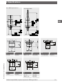
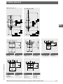
with M12 x 1 circular connector with Metri-Pack series 150 with Deutsch DT04-3P
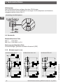
CDS system
All process connections are available with the CDS system.
The diameter of the pressure port is reduced in order to counteract pressure spikes and
cavitation (see fig.1).
Illustration of the CDS system
9.9 Materials
Wetted parts
MH-3: Stainless steel
MH-3-HY: Stainless steel, 2.4711
Non-wetted parts
Highly resistant glass-fibre reinforced plastic (PBT)
9.10 Dimensions in mm
9. Specifications

21WIKA operating instructions, OEM pressure sensor, model MH-3
EN
14136172.03 11/2019 EN/DE/FR/ES
9. Specifications
with cable outlet
with AMP Superseal 1.5
G L1
G ¼ A 14 [0.55]
M14 x 1.5 14 [0.55]
G L1
7/16-20 UNF 12 [0.47]
G L1
¼ NPT 13 [0.51]
G L1
G ¼ B 13 [0.51]
G L1
M14 x 1.5 13.5 [0.53]
Page is loading ...
Page is loading ...
Page is loading ...
Page is loading ...
Page is loading ...
Page is loading ...
Page is loading ...
Page is loading ...
Page is loading ...
Page is loading ...
Page is loading ...
Page is loading ...
Page is loading ...
Page is loading ...
Page is loading ...
Page is loading ...
Page is loading ...
Page is loading ...
Page is loading ...
Page is loading ...
Page is loading ...
Page is loading ...
Page is loading ...
Page is loading ...
Page is loading ...
Page is loading ...
Page is loading ...
Page is loading ...
Page is loading ...
Page is loading ...
Page is loading ...
Page is loading ...
Page is loading ...
Page is loading ...
Page is loading ...
Page is loading ...
Page is loading ...
Page is loading ...
Page is loading ...
Page is loading ...
Page is loading ...
Page is loading ...
Page is loading ...
Page is loading ...
Page is loading ...
Page is loading ...
Page is loading ...
Page is loading ...
Page is loading ...
Page is loading ...
Page is loading ...
Page is loading ...
Page is loading ...
Page is loading ...
Page is loading ...
Page is loading ...
Page is loading ...
Page is loading ...
Page is loading ...
Page is loading ...
Page is loading ...
Page is loading ...
Page is loading ...
-
 1
1
-
 2
2
-
 3
3
-
 4
4
-
 5
5
-
 6
6
-
 7
7
-
 8
8
-
 9
9
-
 10
10
-
 11
11
-
 12
12
-
 13
13
-
 14
14
-
 15
15
-
 16
16
-
 17
17
-
 18
18
-
 19
19
-
 20
20
-
 21
21
-
 22
22
-
 23
23
-
 24
24
-
 25
25
-
 26
26
-
 27
27
-
 28
28
-
 29
29
-
 30
30
-
 31
31
-
 32
32
-
 33
33
-
 34
34
-
 35
35
-
 36
36
-
 37
37
-
 38
38
-
 39
39
-
 40
40
-
 41
41
-
 42
42
-
 43
43
-
 44
44
-
 45
45
-
 46
46
-
 47
47
-
 48
48
-
 49
49
-
 50
50
-
 51
51
-
 52
52
-
 53
53
-
 54
54
-
 55
55
-
 56
56
-
 57
57
-
 58
58
-
 59
59
-
 60
60
-
 61
61
-
 62
62
-
 63
63
-
 64
64
-
 65
65
-
 66
66
-
 67
67
-
 68
68
-
 69
69
-
 70
70
-
 71
71
-
 72
72
-
 73
73
-
 74
74
-
 75
75
-
 76
76
-
 77
77
-
 78
78
-
 79
79
-
 80
80
-
 81
81
-
 82
82
-
 83
83
-
 84
84


WIKA MH-3 User manual
- Type
- User manual
- This manual is also suitable for
Ask a question and I''ll find the answer in the document
Finding information in a document is now easier with AI
in other languages
- français: WIKA MH-3 Manuel utilisateur
- español: WIKA MH-3 Manual de usuario
- Deutsch: WIKA MH-3 Benutzerhandbuch
Related papers
-
WIKA O-10 User manual
-
-
-
-
-
-
-
-
-
Other documents
-
SICK PBT - a genuinely talended all-rounder Product information
-
IFM TA5115 Operating instructions
-
-
-
Sera Diaphragm monitoring for ML KM Operating instructions
-
-
AVENTICS Pressure sensor PE5 Owner's manual
-
-
Honeywell 50038194Honeywell Pressure Switches, HP-HE-MH-ME-LP-LE Series Installation guide
-
GE Baker Hughes PV 212 User manual