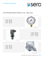
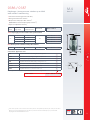
Sera Diaphragm monitoring for ML KM Operating instructions
- Type
- Operating instructions

TECHNICAL MANUAL
TRANSLATION OF THE ORIGINAL TECHNICAL MANUAL! EN
DIAPHRAGM MONITORING for ML-, KM-pumps
C / M / RF 409.2 KM ...
C / M / RF 409.2 ML ...
C / M / RF 410.2 ML
M / RF 410.2 KM
M / RF 409.2 KM
M / RF 409.2 ML
M / RF 410.2 KM
M / RF 410.2 ML
M / RF 409.2 KM
M / RF 409.2 ML
M / RF 410.2 KM
M / RF 410.2 ML
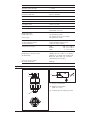
Suco 0186
Baumer RP2E-L03-46
WIKA 213.53


Manometer WIKA 213.53 NG63
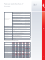
Manometer type Pump type Article-No.
0 - 10 bar
M/RF409.2-11 ML plastic
M/RF409.2-17 ML plastic
M/RF409.2-45 ML plastic
M/RF409.2-110 ML
M/RF409.2-220 ML
M/RF410.2-135 ML plastic
M/RF410.2-500 ML
M/RF410.2-1200 ML
M/RF409.2-7,5 KM plastic
M/RF409.2-10 KM plastic
M/RF409.2-18 KM plastic
M/RF409.2-45 KM plastic
M/RF409.2-95 KM plastic
M/RF409.2-190 KM
M/RF410.2-850 KM
90036189
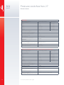
0 - 25 bar
M/RF409.2-11 ML 1.4571
M/RF409.2-17 ML 1.4571
M/RF409.2-45 ML 1.4571
M/RF410.2-135 ML 1.4571
M/RF409.2-95 KM 1.4571
M/RF410.2-310 KM 1.4571
M/RF410.2-510 KM 1.4571
90036190
0 - 100 bar
M/RF409.2-7,5 KM 1.4571
M/RF409.2-10 KM 1.4571
M/RF409.2-18 KM 1.4571
M/RF409.2-45 KM 1.4571
M/RF410.2-150 KM 1.4571
90015032
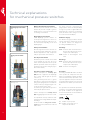
Pressure switch Suco 0186
Pump type Article-No.
C/M/RF 409.2 KM ...
C/M/RF 409.2 ML ...
C/M/RF 410.2 ML
M/RF 410.2 KM
90021225
Pressure switch Baumer RP2E-L03-46
Pump type Article-No.
M/RF 409.2 KM
M/RF 409.2 ML
M/RF 410.2 ML
M/RF 410.2 KM
90013083

Pressure
WIKA data sheet PM 02.12
Page 1 of 4
for further approvals see
page 3
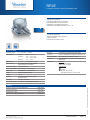
Bourdon tube pressure gauge, model
213.53.100,
lower mount
Applications
■For measuring points with high dynamic pressure loads
and vibrations
■For gaseous and liquid media that are not highly viscous
or crystallising and will not attack copper alloy parts
■Hydraulics
■Compressors, shipbuilding
Special features
■Vibration and shock-resistant
■Especially robust design
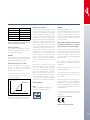
■Type approval for the shipbuilding industry
■Scale ranges up to 0 ... 1,000 bar
Bourdon tube pressure gauge, copper alloy
Stainless steel case, liquid lling, NS 50, 63 and 100
Model 213.53
Data sheets showing similar products:
Stainless steel case, liquid lling, NS 40, 80 and 100; model 113.53; see data sheet PM 01.08
Description
The liquid-lled model 213.53 Bourdon tube pressure gauge
is constructed with a case from stainless steel and wetted
parts from copper alloy.
The model 213.53 meets the requirements of the internati-
onal industry standard EN 837-1 for Bourdon tube pressure
gauges.
Due to the liquid lling in the case, the pressure element and
movement are eciently damped. Therefore, these instru-
ments are particularly suited to measuring points with high
dynamic loads, such as fast load cycles or vibrations.
The cases of the model 213.53 are available in nominal sizes
of 50, 63 and 100 mm and full IP65 ingress protection. With
an accuracy of up to class 1.0, this pressure gauge is suitab-
le for a wide range of applications in industry.
For mounting in control panels, the pressure gauges with a
back mount process connection can be tted with a mounting
ange or with a triangular bezel and mounting bracket.
WIKA data sheet PM 02.12 ∙07/2019

WIKA data sheet PM 02.12 ∙ 07/2019 Page 2 of 4
Dial
NS 50, 63: Plastic ABS, white, with pointer stop pin
NS 100: Aluminium, white, black lettering
Pointer
NS 50, 63: Plastic, black
NS 100: Aluminium, black
Case
Stainless steel, natural nish
Sealing towards process connection with O-ring
With all scale ranges, the lling plug can be vented for inter-
nal pressure compensation.
Position of blow-out device
NS 50: Case back, at 12 o‘clock
NS 63, 100: Case circumference, at 12 o‘clock
Window
Plastic, crystal-clear
Ring
Crimped triangular bezel, stainless steel, glossy nish
Filling liquid
Glycerine
Options
■Other process connection
■Sealings (model 910.17, see data sheet AC 09.08)
■Measuring system and movement from stainless steel
(model 233.53)
■NS 100: Zero point adjustment (in front)
■Increased medium temperature with special soft solder
- NS 50, 63: 100 °C
- NS 100: 150 °C
■Extended ambient temperature range -40 ... +60 °C with
silicone oil lling
■Panel mounting ange, stainless steel, for back mount
connection
■Surface mounting ange, stainless steel (only NS 63, 100)
■Mounting clamp, for back mount
Specications
Design
EN 837-1
Nominal size in mm
50, 63, 100
Accuracy class
NS 50, 63: 1.6
NS 100: 1.0
Scale ranges
NS 50: 0 ... 1 to 0 ... 1,000 bar
NS 63, 100: 0 ... 0.6 to 0 ... 1,000 bar
Pressure limitation
NS 50, 63: Steady: 3/4 x full scale value
Fluctuating: 2/3 x full scale value
Short time: Full scale value
NS 100: Steady: Full scale value
Fluctuating: 0.9 x full scale value
Short time: 1.3 x full scale value
Permissible temperature
Ambient: -20 … +60 °C
Medium: +60 °C maximum
Temperature eect
When the temperature of the measuring system deviates
from the reference temperature (+20 °C): max. ±0.4 %/10 K
of the span
Ingress protection per IEC/EN 60529
IP65
Process connection
Copper alloy
Lower mount or back mount
NS 50, 63: G ¼ B (male), SW 14
NS 100: G ½ B (male), SW 22
Pressure element
NS 50:
Copper alloy, C-type or helical type
NS 63:
≤ 400 bar: Copper alloy, C-type or helical type
> 400 bar: ≥ 400 bar: Stainless steel 316L, helical type
NS 100:
< 100 bar: Copper alloy, C-type
≥ 100 bar: Stainless steel 316L, helical type
Movement
Copper alloy

WIKA data sheet PM 02.12 ∙ 07/2019 Page 3 of 4
Approvals
Logo Description Country
EU declaration of conformity
Pressure equipment directive
PS > 200 bar, module A, pressure accessory
European Union
GOST (option)
Metrology, measurement technology
Russia
KazInMetr (option)
Metrology, measurement technology
Kazakhstan
-MTSCHS (option)
Permission for commissioning
Kazakhstan
BelGIM (option)
Metrology, measurement technology
Belarus
UkrSEPRO (option)
Metrology, measurement technology
Ukraine
Uzstandard (option)
Metrology, measurement technology
Uzbekistan
-CPA
Metrology, measurement technology
China
GL
Ships, shipbuilding (e.g. oshore)
International
-CRN
Safety (e.g. electr. safety, overpressure, ...)
Canada
Certicates (option)
■2.2 test report per EN 10204 (e.g. state-of-the-art
manufacturing, material proof, indication accuracy)
■3.1 inspection certicate per EN 10204 (e.g. indication
accuracy)
Approvals and certicates, see website

WIKA data sheet PM 02.12 ∙ 07/2019 Page 4 of 4
© 09/2008 WIKA Alexander Wiegand SE & Co. KG, all rights reserved.
The specications given in this document represent the state of engineering at the time of publishing.
We reserve the right to make modications to the specications and materials.
07/2019 EN
WIKA Alexander Wiegand SE & Co. KG
Alexander-Wiegand-Straße 30
63911 Klingenberg/Germany
Tel. +49 9372 132-0
Fax +49 9372 132-406
info@wika.de
www.wika.de
Lower mount (radial)
NS 50, 63, centre back mount
Ordering information
Model / Nominal size / Scale range / Process connection / Connection location / Options
Dimensions in mm
Standard version
1224557.01
31059155.01
11081163.01
NS 100, lower back mount
NS Dimensions in mm Weight in kg
a b ±0.5 b2 ±0.5 D1D2e f G h ±1 SW
50 12 30 55 55 50 5.5 -G ¼ B 48 14 0.15
63 13 32 56 68 62 6.5 -G ¼ B 54 14 0.21
100 15.5 48 81.5 107 100 830 G ½ B 87 22 0.80
Process connection per EN 837-1 / 7.3

WIKA Alexander Wiegand SE & Co. KG
Alexander-Wiegand-Straße 30
63911 Klingenberg/Germany
Tel.
+49 9372 132-0
Fax
+49 9372 132-406
info@wika.de
www.wika.de
2408976.06 12/2016
Operating
instructions
1. Safety
WARNING!
Before installation, commissioning and
operation, ensure that the appropriate
pressure gauge has been selected in
terms of measuring range, design and
suitable wetted material (corrosion) for the specic
measuring conditions. In order to guarantee the
measurement accuracy and long-term stability
specied, the corresponding load limits must be
observed.
Only qualied persons authorised by the plant
manager are permitted to install, maintain and
service the pressure gauges.
For hazardous media such as oxygen, acetylene,
ammable or toxic gases or liquids, and refrigera-
tion plants, compressors, etc., in addition to all
standard regulations, the appropriate existing
codes or regulations must also be followed.
From pressure gauges which do not correspond
to a safety version per EN 837 highly pressurised
media might leak out through the possibly burst-
ing window in case of a component failure. For
gaseous media and working pressures > 25 bar a
pressure gauge with safety version S3 is recom-
mended per EN 837-2.
After an external re, pressure media can leak out,
particularly at soft solder joints. All instruments
must be checked and, if necessary, replaced
before recommissioning the plant.
Non-observance of the respective regulations
can cause serious injuries and/or damage to the
equipment.
2. Mechanical connection
In accordance with the general technical regula-
tions for pressure gauges (e.g. EN 837-2). When
screwing the instruments in, the force required to
do this must not be applied through the case, but
only through the spanner ats provided for this
purpose, and using a suitable tool.
For parallel threads, use at gaskets, lens-type
sealing rings or WIKA prole sealings at the
Examples:
Model 213.40
Model 732.14,
overpressure safety
up to 400 bar
Model 432.56,
overpressure safety
up to 100 bar
Pressure gauges
Notes per current pressure equipment directive
The pressure gauges are dened as “pressure
accessories”
The volume of the “pressure-bearing housings” of
WIKA pressure gauges is < 0.1 L
The pressure gauges carry CE marking for uid
group 1 per annex II, diagram 1 when their permis-
sible working pressure is > 200 bar
Instruments that do not carry the mark are manufactured
per article 4, paragraph 3 “sound engineering practice”.
Applicable standards (depending on model)
EN 837-1
Bourdon tube pressure gauges, dimensions,
metrology, requirements and testing
EN 837-2
Selection and installation recommendations
for pressure gauges
EN 837-3
Diaphragm and capsule pressure gauges,
dimensions, metrology, requirements and
testing
Specications: See data sheet at www.wika.de
Subject to technical modications.
© WIKA Alexander Wiegand SE & Co. KG 2009
EN
sealing face . With tapered threads (e.g. NPT
threads), sealing is made in the threads using
additional sealing materials, e.g. PTFE tape
(EN 837-2).
The torque depends on the sealing used. In order
to orientate the measuring instrument so that it
can be read as well as possible, a connection with
clamp socket or union nut should be used.
When a blow-out device is tted to a pressure
gauge, it must be protected against being blocked
by debris and dirt. With safety pressure gauges
(see k) there must be a free space of > 15 mm
behind the blow-out back.
After installation, open the vent valve (if available)
or set from CLOSE to OPEN. With
models 4 and 7, do not open the
ange mounting screws. The version
of the vent valve depends on the
model and can deviate from the above illustration!
Requirements for the installation point
If the line to the measuring instrument is not
adequately stable, a measuring instrument holder
should be used for fastening (and possibly via a
exible capillary). If vibrations cannot be avoided
by means of suitable installation, instruments
with liquid lling should be used. The instruments
should be protected against coarse dirt and wide
uctuations in ambient temperature.
Note for model 732.14, for front bezel mounting:
The front bezel serves as centring and as the
aperture in the mounting panel. Securing and thus
the weight-bearing must be made via the pressure
connection piping.
3. Permissible ambient and operating
temperatures
When mounting the pressure gauge it must be
ensured that, taking into consideration the inu-
ence of convection and heat radiation, no deviation
above or below the permissible temperature limits
can occur. Observe the inuence of temperature
on the indication accuracy!
4. Storage
To protect the pressure gauges from mechanical
damage keep them in the original packaging until
installation.
Protect the measuring instruments from humidity
and dust.
Storage temperature range: -40 ... +70 °C
Storage temperature range model
PG23LT: -70 ... +70 °C
5. Maintenance and repairs
The pressure gauges are maintenance-free.
Regular checks should be carried out to ensure
the measurement accuracy. Checks or recalibra-
tions must only be carried out by qualied skilled
personnel with the appropriate equipment. When
dismounting, close the vent valve (if available).
WARNING! Residual media in
dismounted pressure gauges can
result in a risk to persons, the environ-
ment and equipment. Take sucient
precautionary measures.
Sealing in
the thread
Spanner ats
Sealing face
Installation with
open-ended
spanner
Sealing of the pressure gauge connections

WIKA Alexander Wiegand SE & Co. KG
Alexander-Wiegand-Straße 30
63911 Klingenberg/Germany
Tel. +49 9372 132-0
Fax +49 9372 132-406
info@wika.de
www.wika.de
2408976.06 12/2016
Operating
instructions
1. Safety
WARNING!
Before installation, commissioning and
operation, ensure that the appropriate
pressure gauge has been selected in
terms of measuring range, design and
suitable wetted material (corrosion) for the specic
measuring conditions. In order to guarantee the
measurement accuracy and long-term stability
specied, the corresponding load limits must be
observed.
Only qualied persons authorised by the plant
manager are permitted to install, maintain and
service the pressure gauges.
For hazardous media such as oxygen, acetylene,
ammable or toxic gases or liquids, and refrigera-
tion plants, compressors, etc., in addition to all
standard regulations, the appropriate existing
codes or regulations must also be followed.
From pressure gauges which do not correspond
to a safety version per EN 837 highly pressurised
media might leak out through the possibly burst-
ing window in case of a component failure. For
gaseous media and working pressures > 25 bar a
pressure gauge with safety version S3 is recom-
mended per EN 837-2.
After an external re, pressure media can leak out,
particularly at soft solder joints. All instruments
must be checked and, if necessary, replaced
before recommissioning the plant.
Non-observance of the respective regulations
can cause serious injuries and/or damage to the
equipment.
2. Mechanical connection
In accordance with the general technical regula-
tions for pressure gauges (e.g. EN 837-2). When
screwing the instruments in, the force required to
do this must not be applied through the case, but
only through the spanner ats provided for this
purpose, and using a suitable tool.
For parallel threads, use at gaskets, lens-type
sealing rings or WIKA prole sealings at the
Examples:
Model 213.40
Model 732.14,
overpressure safety
up to 400 bar
Model 432.56,
overpressure safety
up to 100 bar
Pressure gauges
Notes per current pressure equipment directive
The pressure gauges are dened as “pressure
accessories”
The volume of the “pressure-bearing housings” of
WIKA pressure gauges is < 0.1 L
The pressure gauges carry CE marking for uid
group 1 per annex II, diagram 1 when their permis-
sible working pressure is > 200 bar
Instruments that do not carry the mark are manufactured
per article 4, paragraph 3 “sound engineering practice”.
Applicable standards (depending on model)
EN 837-1 Bourdon tube pressure gauges, dimensions,
metrology, requirements and testing
EN 837-2 Selection and installation recommendations
for pressure gauges
EN 837-3 Diaphragm and capsule pressure gauges,
dimensions, metrology, requirements and
testing
Specications: See data sheet at www.wika.de
Subject to technical modications.
© WIKA Alexander Wiegand SE & Co. KG 2009
EN
sealing face . With tapered threads (e.g. NPT
threads), sealing is made in the threads using
additional sealing materials, e.g. PTFE tape
(EN 837-2).
The torque depends on the sealing used. In order
to orientate the measuring instrument so that it
can be read as well as possible, a connection with
clamp socket or union nut should be used.
When a blow-out device is tted to a pressure
gauge, it must be protected against being blocked
by debris and dirt. With safety pressure gauges
(see k) there must be a free space of > 15 mm
behind the blow-out back.
After installation, open the vent valve (if available)
or set from CLOSE to OPEN. With
models 4 and 7, do not open the
ange mounting screws. The version
of the vent valve depends on the
model and can deviate from the above illustration!
Requirements for the installation point
If the line to the measuring instrument is not
adequately stable, a measuring instrument holder
should be used for fastening (and possibly via a
exible capillary). If vibrations cannot be avoided
by means of suitable installation, instruments
with liquid lling should be used. The instruments
should be protected against coarse dirt and wide
uctuations in ambient temperature.
Note for model 732.14, for front bezel mounting:
The front bezel serves as centring and as the
aperture in the mounting panel. Securing and thus
the weight-bearing must be made via the pressure
connection piping.
3. Permissible ambient and operating
temperatures
When mounting the pressure gauge it must be
ensured that, taking into consideration the inu-
ence of convection and heat radiation, no deviation
above or below the permissible temperature limits
can occur. Observe the inuence of temperature
on the indication accuracy!
4. Storage
To protect the pressure gauges from mechanical
damage keep them in the original packaging until
installation.
Protect the measuring instruments from humidity
and dust.
Storage temperature range: -40 ... +70 °C
Storage temperature range model
PG23LT: -70 ... +70 °C
5. Maintenance and repairs
The pressure gauges are maintenance-free.
Regular checks should be carried out to ensure
the measurement accuracy. Checks or recalibra-
tions must only be carried out by qualied skilled
personnel with the appropriate equipment. When
dismounting, close the vent valve (if available).
WARNING! Residual media in
dismounted pressure gauges can
result in a risk to persons, the environ-
ment and equipment. Take sucient
precautionary measures.
Sealing in
the thread
Spanner ats
Sealing face
Installation with
open-ended
spanner
Sealing of the pressure gauge connections

M.
Mechanical Pressure Switches
Mechanical Pressure Switches
10

Pressure switches hex 27
Changeover with silver or gold contacts
Switching point can be adjusted when tted on site1)
Factory adjustable hysteresis (except types 0140 and 0141)
High overpressure safety and long service life under
harsh conditions
Operating voltage up to 250 V
Series 0140 / 0141 with protective insulation
For ready-wired customized versions refer to chapter M.5,
starting at page 62
For pressure switches with integrated connectors refer to
chapter M.2, starting at page 32
•
•
•
•
•
1) Pressure switches can also be supplied preset at factory.
Our preset switches are sealed with lacquer paint, set points are embossed on the housing.
•
•
M.4
hex 27
52

MMM
Pressure switches hex 27
Technical details
Temperature resistance
of sealing materials
Switching frequency
Mechanical life expectancy
Pressure rise rate
Hysteresis
(only adjustable at factory)
Vibration resistance
Shock resistance
Protection class
Weight
NBR (max. overpressure up to 300/600 bar) -40 °C … +100 °C
NBR (max. overpressure up to 100 bar) -30 °C … +100 °C
(in piston pressure switches)
EPDM -30 °C … +120 °C
EPDM-TW (in diaphragm pressure switch) -20 °C … +100 °C
FKM (in diaphragm pressure switch) -5 °C … +120 °C
FKM (in piston pressure switch) -15 °C … +120 °C
FFKM -20 °C … +120 °C
Silicone (in diaphragm pressure switch) -40 °C … +120 °C
HNBR -30 °C … +120 °C
200 / min
1,000,000 cycles (for diaphragm pressure switches, life expectancy
value only applies for switching pressures to max. 50 bar)
≤ 1 bar/ms
Adjustable average value 10 … 30 % depending on type
Types 0140 and 0141 cannot be adjusted
10 g; 5 … 200 Hz sine wave; DIN EN 60068-2-6
294 m/s2; 14 ms half sine wave;
DIN EN 60068-2-6, DIN EN 60068-2-29
IP65 with socket device, terminals IP00
approx. 100 g
Type
5 … 24 V DC
10 … 42 V AC/DC
10 … 250 V AC/DC
3 … 50 mA
10 mA … 2 A
10 mA … 4 A
Gold contacts
Silver contacts
Adjustable hysteresis
Zinc-plated steel (CrVI-free)
Stainless steel 1.4305
Switching performance and materials overview
M.4
hex 27
0140
0141
0170
0171
0180
0181
0183
0186
0187
0190
0191
0196
0197
53

RoHS II
compliant
Pressure switches hex 27
Electrical values
1) For technical explanations refer to page 9
0140 / 0141
Rated working voltage Ue: Rated working current IeUsage category1)
250 VAC 50 / 60 Hz 2 A AC12
24 VDC 2 / 1 A DC12 / DC13
50 VDC 1 / 0.5 A DC12 / DC13
75 VDC 0.5 / 0.25 A DC12 / DC13
125 VDC 0.2 / 0.1 A DC12 / DC13
250 VDC 0.15 / 0.1 A DC12 / DC13
Rated insulation voltage Ui:300 V
Rated impulse withstand voltage Uimp:4 kV
Conventional thermal current Ithe: 5 A
Switching overvoltage: < 2.5 kV
Rated frequency: DC and 50 / 60 Hz
Nominal current of short-circuit
mechanism: to 3.5 A
Rated short-circuit current: < 350 A
IP class of protection
according to DIN EN 60529:1991+A1:1999: IP65 with connector
Tightening torque of terminal screws: < 0.35 Nm
Connector cross-section: 0.5 - 1.5 mm2
0170 / 0171 / 0180 / 0181 / 0183 / 0186 / 0187 / 0190 / 0191 / 0196 / 0197
Rated working voltage Ue: Rated working current IeUsage category1)
250 VAC 50 / 60 Hz 4 A AC12
250 VAC 50 / 60 Hz 1 A AC14
24 VDC 4 / 2 A DC12 / DC13
50 VDC 2 / 1 A DC12 / DC13
75 VDC 1 / 0.5 A DC12 / DC13
125 VDC 0.3 / 0.2 A DC12 / DC13
250 VDC 0.25 / 0.2 A DC12 / DC13
Rated insulation voltage Ui:300 V
Rated impulse withstand voltage Uimp:2.5 kV
Conventional thermal current Ithe: 5 A
Switching overvoltage: < 2.5 kV
Rated frequency: DC and 50 / 60 Hz
Nominal current of short-circuit
mechanism: to 5 A
Rated short-circuit current: < 350 A
IP class of protection
according to DIN EN 60529:1991+A1:1999: IP65 with socket device, terminals IP00
M.4
hex 27
54

RoHS II
compliant
MMM
NBR Hydraulic/machine oil, heating oil, air, nitrogen, etc. 1
EPDM Brake fl uid, water, hydrogen, oxygen, acetylene, etc. 2
EPDM-TW Drinking water (pmax ≤ 35 bar) 5
FKM Hydraulic fl uids (HFA, HFB, HFD), petrol/gasoline, etc. 3
FFKM Chemical acids, diluted alkalis, ketones, ester‘s, alcohols 6
Silicone Water, food products, air, etc. (pmax ≤ 35 bar) 8
HNBR Hydraulic/machine oil, ester-based bio-oils 9
Seal material – Application areas
Refer to page 53 for the temperature range and application thresholds of sealing materials.
0186 / 0187
Diaphragm / piston pressure switches up to 250 V
with stainless steel housing
Stainless steel housing (1.4305 / AISI 303)
Changeover with silver contacts
Overpressure safety up to 400 / 700 bar
1)
(EPDM-TW and silicone diaphragm up to 35 bar
2)
)
Hysteresis adjustable at factory
0186 Diaphragm pressure switches with spade terminal
0187 Piston pressure switches with spade terminal
Article number:
018X – XXX 03 – X – XXX
hex 27
4001)2)
0.5 - 5
1 - 10
± 0.3
± 0.5 G1/4
0186 457 03 X 003
0186 458 03 X 006
10 - 50 ± 3.0
0186 459 03 X 009
10 - 100 ± 3.0 - 5.0
0186 461 03 X 012
7001) 50 - 200 ± 5.0 G1/4
0187 460 03 X 003
Article number
p
max
in bar
Adjustment
range in bar
Tolerance at room
temperature in bar Male thread
1) Static value. Dynamic value is 30-50 % lower. Values pertain to the hydraulic/pneumatic part of the pressure switch.
2) Overpressure safety of diaphragm pressure switch up to 600 bar. Functional reliability only up to 35 bar with
diaphragm materials EPDM-TW and silicone.
M.4
hex 27
9
AMP 6,3 x 0,8
50
G1/4
ø 26
59

General technical explanations
User information
Our pressure monitoring products may
only be installed and started up by
authorised specialists. The safety regula-
tions of country-specic authorities must
be observed, especially when working
with mains voltages and oxygen, and in
potentially explosive areas.
Product information
The technical information in this catalogue
is based upon fundamental testing during
product development and empirical values.
The information cannot be used for all ap-
plication scenarios.
Testing of the suitability of our products
for a specic application (such as the
checking of material compatibilities)
remains the responsibility of the user. It
may be the case that suitability can only
be veried by appropriate eld testing.
Mounting position
For mechanical and electronic pressure
switches as well as transmitters there is no
limitation due to the mounting position
with regard to the accuracy of the pressure
measurement.
However, other boundary conditions of the
application may require a certain mounting
position, e. g. horizontal installation to avoid
waterlogging on the electrical connection
or vertical installation to prevent debris from
accumulating in the bore of the pressure
connection.
IP protection class
The IP protection class is a defined protec-
tion level code (sealing) of electrical equip-
ment housings in line with IEC 60529 (for-
merly DIN 40050 – Part 2). Protection of a
housing against the following is tested here:
• The penetration of solid extraneous
particles, such as dust
• Access of hazardous parts
• Penetration of water
IP protection tests are performed as type
tests.
The IP protection type code, made up of two
digits, specifies the protection of a housing
against the penetration of solid extraneous
particles and water.
The numeric code therefore provides con-
clusions to be drawn on the level of personal
safety as well as the functional protection
/ mid to longterm functional reliability of
electrical equipment.
Protection types IP00, IP65, IP67 and
IP6K9K
IP00:
No protection against penetration of solid
particles or water, no protection against
contact.
IP6X:
Protection against penetration of dust (dust
proof). Full contact protection.
IPX5:
A jet of water from a nozzle, aimed at equip-
ment (such as a pressure switch) from all
directions, must not have any harmful effect.
IPX7:
Protection from water, when equipment
(such as a pressure switch) is immersed in
water under defined pressure and time con-
ditions. Water must not penetrate into the
equipment in harmful quantities.
IP6K9K:
Devices satisfying these requirements must
be dust-proof and be able to withstand loads
during the use of high-pressure cleaners
and steam jets. The standard stipulates a
water pressure from 80 to 100 bar at a tem-
perature of 80 °C for testing.
IP6KX:
Dust must not penetrate. Letter K: Specific
to the electrical equipment of road vehicles.
IPX9K:
Protection against penetration of water at
high pressure / for steam jet cleaning. Water
aimed at the housing from every direction
at greatly increased pressure may not have
any damaging effects.
We are able to oer IP67 / IP6K9K for many
of our mechanical and electronic pressure
switches (pre-wired or with integrated
connector) and for our transmitters.
IP67 / IP6K9K is the recommended pro-
tection for mobile hydraulics and any
equipment exposed to the outdoor
environment.
Cylindrical threads
Cylindrical threads are either sealed on the
front by underlaying an appropriate sealing
ring (such as a copper sealing ring) or by
already having integrated O-rings or gakets.
If the corresponding thread types do not
provide specifications regarding the rough-
ness of the counter sealing surface, we re-
commend the following values:
• Ramax 1,6
• Rmax 6,3
• Rmr(-0,10) > 5 % Cref 5 %
Conical threads
(cone-shaped threads)
Conical threads guarantee tolerance com-
pensation of the two threaded parts. The
sealing function is realised with thread
flanks which deform permanently and enter
into a metallic frictional fit. Conical threads
are not screwed in down to the screw-in
depth, but fixed with the tightening torque
required for the leak tightness.
Remember not to exceed the permitted
tightening torque of the pressure switch or
transmitter presented in the following table
(to prevent damaging the threaded pin
beforehand, causing it to become untight
during operation or to snap off when
tightened).
Tightening torques of steel threads
The specifications below are to be under-
stood upper material thresholds for the
housing of pressure switches or transmit-
ters. Remember during installation that the
type and material of the seal, the condition
of mating surfaces (e.g. dry or oily) and the
material of the counter-piece all have a
bearing on the tightening torque.
8

Thread Tightening torgue
NPT 1/8; M 10 x 1 conical max. 18 Nm
M 10 x 1 cyl.; G 1/8 max. 20 Nm
M 12 x 1.5; 7/16 – 20 UNF max. 30 Nm
G 1/4; 9/16 – 18 UNF max. 40 Nm
NPT 1/4; M 14 x 1.5 max. 40 Nm
Values 30% lower than in the table above
must be used for brass housings.
Gaseous applications
In particular using additional sealant to
attain the required leak tightness may be
necessary for gas applications.
Vacuum
The values given in the technical details for
the vacuum range are specified in millibars
(mbar) below atmospheric pressure.
Pressure change rate (~rise / ~fall)
The pressure change rate denotes the
pressure over time for the rising/falling
pressure. The pressure change rate is
specified in bar/s or bar/ms.
The maximum pressure change rate for
SUCO mechanical pressure switches is
1 bar/ms (1,000 bar/s).
For SUCO electronic pressure monitoring
products the maximum pressure change
rate can be up to 5 bar/ms (5,000 bar/s).
Overpressure protection
The specified overpressure protection in the
catalogue is based on a static pressure. The
values refer to the hydraulic or pneumatic
part of the switch. It is best practice to use
30 - 50% lower values for dynamic pressure
compared to static pressure. These empiri-
cal values are based on the knowledge that,
in pressure systems, unexpected pressure
peaks which are higher than the working
pressure are generated as a result of activa-
tion of valves, sudden falling or rising load
or simply the change of cross-sections in
the pipes. With conventional measurement
techniques (such as manometers), these
pressure peaks are hardly measureable.
Faster measurement systems must there-
fore be used for this data acquisition.
Attempts are being made to take this into
account by using emperical or corrective
factors.
If the pressure conditions are known and
the pressure change rates are 0.1 bar/ms,
our pressure switches and transmitters can
be used up to the permitted overpressure
protection as per data sheet / catalogue.
Only 50 % of the specified overpressure pro-
tection is permitted when operating at the
maximum permitted pressure change rate
of ≤ 1 bar/ms for mechanical pressure
switches, and at ≤ 5 bar/ms for transmitters.
RoHS-Compliance
RoHS
= Restriction of Hazardous Substances
(EC Directive 2011/65/EU (RoHS II)
CE-Mark
= Communauté Européenne
European Parliament and Council directives
must be observed when products are
launched onto the market. If a directive
exists for a product, it must be applied. Only
products for which a directive exists may
bear the CE mark.
Only products which have been tested
according to CE directive or correspon-
ding standards may carry the CE mark.
Mechanical pressure switches with a supply
voltage above 50 VAC or 75 VDC are covered
by the 2014/35/EU Low Voltage Directive.
Variants for potentially explosive areas are
covered in addition by the 2014/34/EU ATEX
Product Directive.
Our electronic products satisfy EMC
(Electromagnetic Compatibility) Directive
2014/30/EC.
Mechanical pressure switches do not fall
under the EMC Directive.
The Machinery Directive 2006/42/EC is not
applicable, because our products are classed
as components.
Our product designs are based upon „good
engineering practise“ in line with Article 4,
Paragraph 3 of the Pressure Equipment
Directive (2014/68/EU), meaning neither a
declaration of conformity may be issued nor
a CE mark affixed.
The current product-specific CE declarati-
on is available in the download area of our
homepage:
www.suco.de/en/downloads
Subject to technical changes
pressure / p
time / s
dt
9

What is a mechanical pressure switch?
Mechanical pressure switches from SUCO
monitor the pressure of liquid or gaseous
media, and close or open an electrical circuit
on reaching a set threshold.
Diaphragm pressure switches
SUCO diaphragm pressure switches are
used in pressure ranges from 0.1 bar to 100
bar, meaning overpressure safety of 35, 100,
300 and 600 bar, depending on the used
diaphragm type.
Piston pressure switches
Pressure ranges from 10 bar to 400 bar can
be monitored with SUCO piston pressure
switches (dependent on size); overpressure
safety of up to 600 bar can be attained.
Sizes of pressure switches
Mechanical pressure switches from SUCO
can be divided into sizes hex 24, hex 27
and 30 A/F. Each particular size has specifi c
hydraulic, pneumatic and electric properties
(specifi ed on the relevant catalogue page in
the technical details).
How does a pressure switch work?
Function description for normally open
(NO): Pressure is applied to the diaphragm
(2a) / pistons (2b) through the pressure
connector (1).
If the generated pressure force is greater
than the force of the pre-tensioned pressure
spring (3), the plunger (4) moves towards the
counter-contact (6), carrying along the cont-
act disc (5), and closes the circuit.
The switch opens again when the pressure is
reduced by the hysteresis value.
Function description for normally closed
(NC): Engaging happens in the reverse order.
The adjustment screw (7) enables the swit-
ching point to be changed within the adjust-
ment range.
The micro switch of a change-over contact
system (snap-action) off ers both, a NC and
a NO contact.
The swivel contact (9) is activated by the
plunger (4). The circuit is closed by the NC (8)
as long as no pressure is applied. When the
applied pressure exceeds the set switching
point, the swivel contact changes over and
closes the circuit via the NO (10).
Utilisation category
The utilisation category specifi es for example
voltages and currents, and the type of load,
our pressure switches are designed for
(according to DIN EN 60947-5-1).
AC voltage
AC12: Control of ohmic loads and semicon-
ductor loads in input circuits of opto-
couplers (such as PLC inputs).
AC14: Control of electromagnetic loads,
72 VA.
DC voltage
DC12: Control of ohmic loads and semicon-
ductor loads in input circuits of opto-
couplers (such as PLC inputs).
DC13: Control of electromagnets.
B10d value
According to DIN EN ISO 13849-1, the B10d
value specifi es the anticipated service life
(with a 10% probability of failure). The B10d
value is therefore directly dependent on the
respective application of the pressure switch.
For ohmic loads and currents < 1 A, we specify
the B10d value as 1 million cycles of electrical
life.
The specifi cation of a MTTF time (mean time
to failure) is not possible without knowing
the specifi c conditions in the application.
However, the MTTF time can be determined
easily from the B10d value:
nop: number of cycles per year
B10d: number of cycles until 10 % of
components have failed.
Technical explanations
for mechanical pressure switches
Diaphragm pressure switch
NO
Piston pressure switch
NC
Change-over
1
2a
3
7
6
5
4
2b
3
7
6
5
4
9
10
8
4
14
1

MMM
Minimum current /
minimum working voltage
The minimum working current and minimum
working voltage depend greatly on operating
and ambient conditions. Physically, the build-
up of impurity layers on the contact rivets must
be countered with mechanical friction and/or
electrical erosion.
It has proven useful in many applications to de-
ploy our pressure switches with silver contact
rivets ensuring that they are fail safe to 10 mA
and 10 V. Variants with gold contacts are avai-
lable in our catalogue for even lower currents
and voltages.
Potential-free – galvanically isolated
Mechanical pressure switches from SUCO are
potential-free, i.e. no auxiliary energy is requi-
red. Also, there is no electrical contact between
the individual, live parts and the housing.
Adjustment range of switching point
The pressure range, within which the switching
point of a pressure switch can be set, is called
adjustment range. The switching point corres-
ponds to the pressure value at which the elec-
tric circuit is opened or closed by the pressure
applied.
If no switching point is specifi ed on order, the
pressure switches are adjusted by approxima-
tely half the adjustment range at factory.
Switching point tolerances
The switching point tolerances specifi ed by us
pertain to room temperature (RT) and condi-
tion as new. The values can change as a result
of temperature, ageing and deployment con-
ditions.
It is not possible to specify generally applica-
ble value for switching point tolerances over
temperature as the medium has a signifi cant
infl uence on the sealing materials in the pres-
sure switch.
Double the tolerance stated for RT and condi-
tion as new can be assumed as a typical mag-
nitude for the tolerance over the entire tempe-
rature range.
Based on their design, piston switches may
exhibit an increase in switching points due to
storage (dry run, stick-slip eff ect). Following a
short start phase, the switching points return
to the value set at the factory.
Pressure change rates of > 1bar/s may have an
eff ect on the switching point for diaphragm
pressure switches.
The switching point (for rising pressure) and
hysteresis increase, whilst the switch-back
point (for falling pressure) sinks. Also, the ef-
fect of the maximum (system) pressure on the
switchback point (for falling pressure ramp)
must be factored in for tolerance-critical appli-
cations. The higher the (system) pressure, the
lower the resulting switch-back value.
Hysteresis
Rising / falling switching point
The pressure diff erence between the rising
(upper) and falling (lower) switching points
(refer to the fi gure, e.g. NO) is known as hystere-
sis (switch-back diff erence).
Hysteresis has no constant value due to the
structural layout of a mechanical pressure
switch. In absolute values, the hysteresis is
also the smallest with the smallest adjustment
range. The hysteresis increases with increasing
adjustment range.
Hysteresis over rising switching point
Upper switching point
Lower switching point
Increasing
pressure
falling
pressure
Hysteresis
Classi cation of electrical switch functions
Contact form
DIN EN-
60947-5-1
Symbol
IEC 60617
NO NO,
normally open
SPST
single pole,
single throw X
NC NC,
normally closed
SPST
single pole,
single throw Y
Change-
over
contacts
CO,
change over
(snap action)
SPDT
single pole,
double throw C
001 0 20 40 60 80
001 0 20 40 60 80
Hysteresis relative value
[%]
Hysteresis absolute value
[bar, PSI, Pa]
Hysteresis min.
Hysteresis max.
rising swichting point [%]
Hysteresis min.
Hysteresis max.
rising swichting point [%]
15

Technical explanations
for mechanical pressure switches
ECO (epichlorhydrin)
ECO is only used in our vacuum switches.
This material has similar properties to NBR
in terms of chemical resistance, and can be
used in gas applications as well as oil and
fuel applications.
ECO is denoted by number „4“ in our order
number.
Silicone
Silicone is suitable for use within a wide
temperature range. The SUCO silicone
diaphragm is FDA-approved (Food & Drug
Administration) for the food sector.
Silicone is a soft material reserved for sen-
sitive applications in the low pressure range
(below 10 bar) with maximum overpressure
safety to 35 bar. Piston switches are therefore
not off ered with silicone seals. Silicone is also
not suitable for oil applications.
Silicone is denoted by number „8“ in our
order number.
H-NBR
This is a special SUCO material mixture opti-
mised for ester-based bio-oils. The multitude
of bio-oils on the market means suitability
of the material for the respective oil must
be determined. This diaphragm material can
also be used for a number of mineral and
synthetic oils.
H-NBR is denoted by number „9“ in our order
number.
Medium compatibility
The specifi cations on medium compatibility
in this catalogue cannot be generalised as
they pertain to the sealing materials used in
our pressure switches.
Saturated and superheated steam
applications
The sealing materials mentioned are not
suitable for saturated or superheated steam
applications.
Hysteresis can be set at SUCO in range from
approx. 10 % (at end of adjustment range) to
30 % or higher (at start of adjustment range),
related to the respective switching point for
hex 27 and 30 A/F pressure switches with ad-
justable hysteresis.
The specifi cations in the catalogue only repre-
sent typical average values.
Please ask about the possible setting ranges
you may require. Our electronic pressure swit-
ches are excellently suited to extremely low or
high hysteresis.
The lowest possible hysteresis is set if nothing
is specifi ed in the order.
Switching frequency
The switching frequency provides information
on the possible number of cycles in one
minute. The value of 200/minute specifi ed
by us is a guideline value. Higher switching
frequencies can be attained depending on
switch type and conditions of use.
Sealing materials
The priority in sealing material selection is the
chemical resistance. The temperature range
only becomes a selection criterion when
diff erent sealing materials are suitable for the
medium.
NBR (Buna-N)
This is the standard material most commonly
used. It is a special SUCO material mix with
high level of cold fl exibility so that the sea-
ling properties of the pressure switch are also
retained at low temperatures.
NBR is denoted by number „1“ in our order
number.
EPDM
This material is the solution of choice for
applications with brake fl uids. It is particularly
suitable for applications with (process) water.
Approval from the BAM (Federal Institute for
Material Testing) is in place for oxygen appli-
cations. The safety regulations from country-
specifi c authorities must be observed for
oxygen applications.
EPDM may not come into contact with oil
because this would entail swelling and soft-
ening of the material, and so failure of the
pressure switch.
EPDM is denoted by number „2“ in our order
number.
EPDM-TW with drinking water approval
This EPDM material is intended for drinking
water applications according to Elastomer
Guideline, WRAS (Water Regulation Advisory
Scheme), ACS (Attestation de Conformité
Sanitaire) and NSF 61 (National Sanitation
Foundation) and for use in medical and
pharmaceutical applications.
EPDM-TW may not come into contact with
oil because this would entail swelling and
softening of the material, and so failure of
the pressure switch. Sealing is only available
upon request, so please consult us before
ordering.
EPDM-TW is denoted by number „5“ in our
order number.
FKM / FPM (Viton®)
This is a diaphragm material suitable for high
temperature exposure and exhibits special
chemical resistance. It has been tested in
the hydraulic sector and has been proven to
work successfully with critical oils.
FKM / FPM is denoted by number „3“ in our
order number.
FFKM
This diaphragm material is suitable for tem-
perature exposure up to 120°C and can
withstand very aggressive conditions such
as chemical species including organic or in-
organic acids, diluted alkalis, ketones, esters,
alcohols, fuels and hot water.
FFKM is denoted by number „6“ in our order
number.
TPE (Thermoplastic elastomers)
This sealing material is available only for our
electronical products of the Performance
Series.
TPE off ers similar media compatibility like
NBR, e.g suitable for mineral oil and hydraulic
fl uids.
Additionally the material can be used with
diluted acids and bases and cold water, too.
TPE is denoted by number „7“ in our order
number.
16

-
MMM
K °C F
K 1 K - 273.15 9/5 K - 459.67
°C °C + 273.15 1 9/5 °C + 32
F 5/9 (F + 459.67) 5/9 (F - 32) 1
For gaseous applications below 10 bar (145
PSI) in combination with pressure switches
with high IP class, i.e. IP 67 and IP6K9K, in
general we recommend to use ventilation.
Please consult us; we are able to o er
suitable solutions.
Oxygen applications
Our mechanical pressure switches are suitable
for use with oxygen. We recommend the
use of our EPDM diaphragm. The resistance
to internal burnout of the diaphragm has
been tested by the BAM (Federal Institute for
Material Testing).
Pressure switches with steel housings with
zinc-nickel coating are, in conjunction with
oxygen, only approved to a maximum wor-
king pressure of 10 bar.
Pressure switches with brass housings are,
in conjunction with oxygen, only approved
to a maximum working pressure of 35 bar.
Pressure switches with stainless steel
housings are, in conjunction with oxygen,
only approved to a maximum working pres-
sure of 50 bar.
DGUV accident prevention regulations (such
as DGUV 500, Section 2.32 and BGI 617) must
be observed for fi rst operation.
Please specify when ordering „oil and grease-
free, for use with oxygen“.
Underpressure safety of pressure switches
Our pressure switches are underpressure safe
down to 300 mbar (relative).
Overpressure safety of vacuum switches
Our vacuum switches are overpressure safe
up to 20 or 35 bar depending on type.
cCSAus approval
Almost all of our mechanical pressure switches
(sizes hex 24 and hex 27), and vacuum switch
0151, have cCSAus approval. The CSA mark
together with „c“ and „us“ combines the control
stamps for introduction onto the Canadian
and American markets. The cCSAus certifi cate
also includes the test of the relevant UL stan-
dard.
Checked by an offi cial institution and verifi ed
with regular company visits by CSA inspectors,
this approval guarantees the highest levels of
quality and operational reliability for our pro-
ducts.
You can download the current cCSAus certifi -
cate on the download area of our homepage:
http://www.suco.de/en/downloads
Product information
The technical information in this catalogue
is based upon fundamental testing during
product development, as well as upon empi-
rical values. The information cannot be used
for all application scenarios.
Testing of the suitability of our products for
a specifi c application (e.g. also the checking
of material compatibilities) rests under the
responsibility of the user. It may be the case
that suitability can only be guaranteed with
appropriate fi eld testing.
Water applications
Standard piston switches are not suitable for
water applications.
Pressure switches in stainless steel with
EPDM seal have a special sealing system and
can therefore also be used for water with
corrosion protection, water mixtures or
emulsions. The use of other fl uid mixtures
should be clarifi ed with SUCO (e.g. swelling
of EPDM sealing could happen by water – oil
mixture).
Pressure switches with stainless steel
housings with EPDM-TW diaphragm, SUCO
type „5“ are designed for the use of drinking
water.
Gas applications
Our pressure switches are suitable for liquid
and gaseous media. Gaseous media place
particular demands on leak-tightness how
ever. The leakage rate is dependent on the
respective gaseous medium, the working
pressure and the permeability of the seal
material used in the pressure switch.
Their lower leakage rates mean diaphragm
pressure switches are better suited for gas
pressures than piston pressure switches. The
latter can also be used however if certain
measures are taken (such as venting of the
housing).
Conversion table for pressure units
Conversion table for temperature units
Unit symbol Unit name Pa= N/m² bar Torr lbf/in², PSI
1 Pa = N/m² Pascal 1 0.00001 0.0075 0.00014
1 bar Bar 100 000 1 750.062 14.5
1 Torr = 1 mmHg Millimetres,
mercury column 133.322 0.00133 1 0.01934
1 lbf/in² = 1 PSI Pound-force
per square inch 6 894 0.06894 51.71 1
Please consult us about gas, water and oxygen applications.
Subject to technical changes. 17
Page is loading ...
Page is loading ...
Page is loading ...
Page is loading ...
Page is loading ...
Page is loading ...
Page is loading ...
Page is loading ...
Page is loading ...
Page is loading ...
Page is loading ...
Page is loading ...
Page is loading ...
Page is loading ...
Page is loading ...
Page is loading ...
Page is loading ...
Page is loading ...
-
 1
1
-
 2
2
-
 3
3
-
 4
4
-
 5
5
-
 6
6
-
 7
7
-
 8
8
-
 9
9
-
 10
10
-
 11
11
-
 12
12
-
 13
13
-
 14
14
-
 15
15
-
 16
16
-
 17
17
-
 18
18
-
 19
19
-
 20
20
-
 21
21
-
 22
22
-
 23
23
-
 24
24
-
 25
25
-
 26
26
-
 27
27
-
 28
28
-
 29
29
-
 30
30
-
 31
31
-
 32
32
-
 33
33
-
 34
34
-
 35
35
-
 36
36
-
 37
37
-
 38
38


Sera Diaphragm monitoring for ML KM Operating instructions
- Type
- Operating instructions
Ask a question and I''ll find the answer in the document
Finding information in a document is now easier with AI
in other languages
Related papers
-
Sera Piston diaphragm pump 409.2KM 410.2KM Operating instructions
-
-
-
-
-
-
-
-
Other documents
-
IFM IN509A Operating instructions
-
IFM PC5104 Operating instructions
-
 LABOM PASCAL DELTA P CI133 Operating instructions
-
IFM PT5500 Operating instructions
-
WatchGas ATEX Beacon Sounder Explosion-Proof Audio and Visual Caution Spotlight User guide
-
Atos SHD250 Owner's manual
-
-
-
 HEISE CMM Installation and Maintenance Manual
-

