Eaton Neo-Ray Define S122-125 DP Installation guide
- Type
- Installation guide

INS #
IL524025EN
Neo-Ray
Risk of Fire, Electrical Shock, Cuts or other Casualty Hazards- Installation and maintenance of this
product must be performed by a qualified electrician. This product must be installed in accordance
with the applicable installation code by a person familiar with the construction and operation of the
product and hazards involved.
Risk of Fire and Electric Shock- Make certain power is OFF before starting installation or attempting
any maintenance. Disconnect power at fuse or circuit breaker.
Risk of Fire- Minimum 90°C supply conductors.
Risk of Burn- Disconnect power and allow fixture to cool before handling or servicing.
Risk of Personal Injury- Due to sharp edges, handle with care.
Failure to comply with these instructions may result in death, serious bodily injury and property
damage.
WARNING
DISCLAIMER OF LIABILITY: Eaton assumes no liability for damages or losses of any kind that may arise from the
improper, careless, or negligent installation, handling or use of this product.
IMPORTANT: Read carefully before installing fixture. Retain for future reference.
NOTICE: Green ground screw provided in proper location. Do not relocate.
NOTICE: Fixture may become damaged and/or unstable if not installed properly.
Note: Specifications and dimensions subject to change without notice.
ATTENTION Receiving Department: Note actual fixture description of any shortage or noticeable damage on
delivery receipt. File claim for common carrier (LTL) directly with carrier. Claims for concealed damage must be
filed within 15 days of delivery. All damaged material, complete with original packing must be retained.
Installation Instructions – Define S122-125 DP/RDP/DIP/RDIP
Wiring Table
Power Supply (Input) When Applicable
Black (BK) - Hot
White (WH) - Neutral
Green (GN) - Ground
Purple (PU) - 0-10V (+)
Gray (GR) - 0-10V (-)
Emergency Hot – Black/Red
Emergency Neutral – White/Red
Second Circuit Hot – Black/Orange
Second Circuit Neutral – White/Orange
Second Circuit Dimming Positive – Orange
Second Circuit Dimming Negative – Yellow
Battery/Emergency Unswitched Hot – Blue
Maximum Sink/Source current per fixture is 12mA

Installation Instructions – Define S122-125 Suspended LED Luminaire
Installation Instructions – Define S122-125 DP/RDP/DIP/RDIP
IL524025EN www.eaton.com
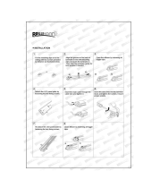
INSTALLATION
Define DP/RDP/DIP/RDIP (2”- 5” Housing Size)
Individual and Continuous Luminaires - Installation
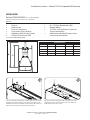
Turn off power before installation. Connect mounting kits at pre-
specified locations according to your specific ceiling type (see
submittal for dimensional details). Remove fixture from box and
remove access plate by removing four #8-32 screws.
Pull aircraft cable through griplocks® and adjust to desired
height. Make sure to level the fixture correctly (applies to
individuals or first piece in row).
Parts List
• Fixture
• Access Plate
• Push In Connectors
• Cast Joiner & Torx Screws
• Additional 8-32 Phillips Screws
• Phillips Screw Driver (Bit)
• 6L – T15 Torx Screwdriver (Bit)
• Rubber Mallet
• T-15 Torx Joining Screws (2 per row
fixture connection)
• #8-32 Joining Bracket Screws (2 per
row fixture connection)
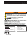
Cross Section and Grid Spacing Details
W
X
Y
V
1
2
DP/RDP/DIP/RDIP
All Grid V (Flush) W (Regressed) X Y
Define 2 4.132 5.132 2.000 1.680
Define 3 4.567 5.567 3.000 2.680
Define 4 5.132 6.132 4.000 3.680
Define 5 5.632 6.632 5.000 4.680

Installation Instructions – Define S122-125 Suspended LED Luminaire
Installation Instructions – Define S122-125 DP/RDP/DIP/RDIP
IL524025EN www.eaton.com
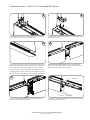
Attach strain relief to SJ Cord and pull SJ cord through access
plate to lock SJ cord in place on access plate.
3
Connect power and dimming leads to SJ cord as required using
wire nuts (by others)
4
Once power and dimming wires are connected, push the wiring
back into the fixture and re-attach the access plate. Individual
fixtures will have the diffuser and diffuser end caps already
installed. For rows, remove the diffuser and diffuser clip and set
aside. Row fixtures require internal joining so the diffuser must
be removed and re-installed after row installation is completed.
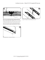
FOR CONTINUOUS ROWS ONLY: Hang far end of the next
fixture in the row using the griplock® and pre-installed aircraft
cable. Temporarily support the other end.
Connect power and dimming wires using provided push in
connec tors and stuff back into fixture.
Use the Cast Joiners, alignment pins, and fixture tongue to align
and guide the fixtures together.
5 6
7
8
Alignment Pins Cast Joiner
Fixture Tongue

Installation Instructions – Define S122-125 Suspended LED Luminaire
Installation Instructions – Define S122-125 DP/RDP/DIP/RDIP
IL524025EN www.eaton.com
While one person holds fixtures in place check to make sure
fixture is level. DO NOT WALK AWAY LEAVING THE FIXTURES
UNFASTENED BY MECHANICAL MEANS. Fixture can be leveled
via grip lock on opposite end of fixture. Once fixtures are flush
to one another and level install torx head screw through cast
joiners to snug fixtures together. DO NOT OVER TIGHTEN. Torx
screw will pull fixtures together tightly without too much force.
Screw #1/4-20 Screw into extrusion and through the fixture
tongue to complete mechanical joining of fixtures
Re-install diffusers to complete installation.
9
10
11
Torx Screw

Eaton is a registered trademark.
All trademarks are property
of their respective owners.
Eaton est une marque de commerce
déposée. Toutes les autres marques
de commerce sont la propriété de leur
propriétaire respectif.
Eaton es una marca comercial
registrada. Todas las marcas
comerciales son propiedad de sus
respectivos propietarios.
Eaton
18001 East Colfax Ave
Aurora, CO 80011
P: 800-553-3879
www.eaton.com/lighting
© 2019 Eaton
All Rights Reserved
Printed in USA
Imprimé aux États-Unis
Impreso en los EE. UU.
Publication No. IL524025EN
December 3, 2019
Product availability, specifications,
and compliances are subject to
change without notice
La disponibilité du produit, les
spécifications et les conformités
peuvent être modifiées sans préavis
La disponibilidad de productos, las
especificaciones y los cumplimientos
están sujetos a cambio sin previo aviso
Warranties and Limitation of Liability
Please refer to www.cooperlighting.com/WarrantyTerms for our terms and conditions.
Garanties et limitation de responsabilité
Veuillez consulter le site www.cooperlighting.com/WarrantyTerms pour obtenir les conditions générales.
Garantías y Limitación de Responsabilidad
Visite www.cooperlighting.com/WarrantyTerms para conocer nuestros términos y condiciones.
FCC Statement
• This device complies with Part 15 of the FCC Rules.
Operation is subject to the following two conditions:
(1) This device may not cause harmful interference.
(2) This device must accept any interference received,
including
interference that may cause undesired operation.
Note: The grantee is not responsible for any changes
or modifications not expressly approved by the party
responsible for compliance. Such modifications could
void the user’s authority to operate the equipment.
Note: The equipment has been tested and found to
comply with the limits for a Class B digital device,
pursuant to part 15 of the FCC Rules.
These limits are designed to provide reasonable
protection against harmful interference in a residential
installation. This equipment generates uses and can
radiate radio frequency energy and, if not installed and
used in accordance with the instructions, may cause
harmful interference to radio communications. However,
there is no guarantee that interference will not occur in
a particular installation. If this equipment does cause
harmful interference to radio or television reception,
which can be determined by turning the equipment
off an on, the user is encouraged to try to correct the
interference by one or more of the following measures:
• Reorient or relocate the receiving antenna.
• Increase the separation between the equipment and
receiver.
• Connect the equipment into an outlet on a circuit
different from that to which the receiver is connected.
• Consult the dealer or an experienced radio/TV
technician for help.
This device complies with FCC radiation exposure
limits set forth for an uncontrolled environment. This
equipment must be installed and operated in accordance
with provided instructions and the antenna(s) used for
this transmitter must be installed to provide a separation
distance of at least 20 cm from all persons.
-
 1
1
-
 2
2
-
 3
3
-
 4
4
-
 5
5


Eaton Neo-Ray Define S122-125 DP Installation guide
- Type
- Installation guide
Ask a question and I''ll find the answer in the document
Finding information in a document is now easier with AI
Related papers
-
Eaton Cooper Lighting Night Falcon UFLD Series Installation Instructions Manual
-
-
-
-
-
-
-
-
-
Other documents
-
Cree BA19-08027OMF-12CE26-1C100 User manual
-
-
-
-
Cooper Neo-Ray Define S122 IP Installation guide
-
 Brillihood LED Vapor Proof 4ft Light Fixture, 36 Watt, 4000lm, 6000K (Bright White), Clear Cover, IP65 Waterproof 4' Long Overhead Shop Light, Indoor/Outdoor Lighting, 4-Pack Installation guide
-
brandon MX452 User manual
-
 superbrightleds com MX452 User manual
-
Metalux SNF120P Operating instructions
-
Biamp Pendant Hanging Kit (MC-PHK16-12pk) Installation & Operation Guide

