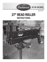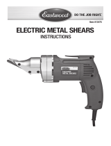
VISE PRESS BRAKE
INSTRUCTIONS
Item #21640
#21641

2 Eastwood Technical Assistance: 800.343.9353 >> techelp@eastwood.com
The EASTWOOD 4” AND 6” VISE PRESS BRAKES are precision engineered metal working tools
designed to produce crisp, accurate, bends at angles up to 90° in mild steel and aluminum up to
14 gauge, and 18 gauge stainless in widths up to 4” for the 21640 and 6” for 21641. Create complex
shapes such as reinforcement channels, ribs and much more all with one convenient, easy to store tool.
CONTENTS
(1) Male Die Holder/Dies
(1) Female Die
DANGER indicates a hazardous situation which, if not avoided, will result in death or serious injury.
WARNING indicates a hazardous situation which, if not avoided, could result in death or serious injury.
CAUTION used with the safety alert symbol, indicates a hazardous situation which, if not avoided,
could result in minor or moderate injury.
NOTICE is used to address practices not related to personal injury.
SAFETY INFORMATION
The following explanations are displayed in this manual, on the labeling, and on all other information
provided with this product:

To order parts and supplies: 800.343.9353 >> eastwood.com 3
READ INSTRUCTIONS
• Thoroughly read and understand this manual before using.
• Save for future reference.
PINCH AND CRUSH HAZARD!
• The Eastwood Vise Press Brake consists of sharp metal components which
can present a hand/finger pinch hazard and cause potentially serious
injuries. Avoid pinching hands while handling. Keep fingers and hands away
from moving parts when operating.
CUT HAZARD!
• Handling sharp metal can cause serious cuts. Wear thick, well-fitting work
gloves to prevent cuts from handling sharp metal.
EYE INJURY HAZARD!
• Metal particles can be ejected from the metal surface when bending.
Sheet metal edges and corners are sharp and can injure eyes.
Always wear ANSI approved eye protection when operating this tool.
• Before beginning ANY work with this tool, it is absolutely necessary that it
be mounted in a properly sized vise securely bolted to a sturdy, workbench
anchored to the floor or wall.
• Strenuous physical force may need to be applied to the Vise Press Brake
during use. Failure to ensure proper footing can quickly result in a fall which
could inflict serious personal injury or property damage. Always work in a
clean, uncluttered environment.
• Be sure there is sufficient working room around the tool to allow for safe
handling of various sizes of metal.
• Excessive resistance while operating could indicate a defect with the
workpiece material or broken or damaged Vise Press Brake components.
To avoid injury, stop work immediately and inspect workpiece material for
nicks, dents, welds, excessive scale or remaining coatings. Clean or repair
as necessary or discard and begin with a new piece. Also inspect Vise Press
Brake components for looseness or damage.
SAFETY INFORMATION

4 Eastwood Technical Assistance: 800.343.9353 >> techelp@eastwood.com
SET-UP
Use only in a vise properly sized for the Eastwood Vise Press Brake. Use a 4” or larger vise for the
4” Vise Press Brake and a 6” or larger vise for the 6” Vise Press Brake.
• Place into Vise jaws with the built-in magnets against the face of the jaws and the cast-in
locating tabs over the top of the jaws (FIG 1).
The Eastwood Vise Press Brakes are designed only for use in a properly and
securely mounted Vise.
FIG. 1

To order parts and supplies: 800.343.9353 >> eastwood.com 5
OPERATION
• Measure and mark the desired bend line on the workpiece panel.
• Slide metal panel between the Dies lining up your pre-marked bend line with the sharp, beveled
edge of the Male Die (FIG 2).
• Gently and slowly draw the Vise jaws together to begin creating the desired bend.
NOTE: The use of an angle gauge or protractor (not included) is recommended.
• Depending on the alloy being bent, it may be necessary to push the dies slightly beyond the
desired finished angle to allow for “springback”. Some trial and error is suggested using scrap
material before making final bends.
FIG. 2

6 Eastwood Technical Assistance: 800.343.9353 >> techelp@eastwood.com
REMOVING & REPLACING DIE FINGERS
The individual Die Fingers located in the Male Die may be removed and rearranged for greater
precision in bending workpieces or may be replaced if nicks or damage should occur.
• To Remove
Using a 5mm Hex Key (not included), loosen the socket head cap screws and remove the
desired Die Fingers (FIG 3).
• To Replace
Insert Die Fingers into the Male Die as required, use care to properly align the sharp bending
edges then, once again, using a 5mm Hex Key, tighten all screws.
FIG. 3

To order parts and supplies: 800.343.9353 >> eastwood.com 7
MAINTENANCE
• Keep all areas of the Dies clean, particularly those surfaces that contact sheetmetal
workpieces. Dirt and metal chips can cause uneven clamping and inaccurate bends.
• Store in a clean & dry environment when not in use. Coat all machined surfaces with
a light film of oil, or suitable protectant, to prevent rust formation.

© Copyright 2018 Easthill Group, Inc. 4/18 Instruction item #21642Q Rev 1
If you have any questions about the use of this product, please contact
The Eastwood Technical Assistance Service Department: 800.343.9353 >> email: techelp@eastwood.com
PDF version of this manual is available at eastwood.com
The Eastwood Company 263 Shoemaker Road, Pottstown, PA 19464, USA
800.343.9353 eastwood.com
ADDITIONAL ITEMS
#28038 Sheet Metal Gauge
#13475 Electric Metal Cutting Shears
#28187 Bead Roller Kit
#51088 Shrinker/Stretcher Set
/

