Page is loading ...

1
USER MANUAL
VERSION 3.1
APRIL 2018

2
Manufactured under license from Dolby Laboratories.
Dolby and the double-D symbol are trademarks of Dolby Laboratories.

3
TABLE OF CONTENTS
Important Safety Information ....................................................................................................5
CHAPTER 1 Introduction to SMARTBOX ....................................................................................... .8
Site Requirements ..........................................................................................................8
Installation Overview ....................................................................................................... 9
CHAPTER 2 Assemble Chassis, Power Supplies, and Power Inserters .....................................................10
Install Chassis and Power Supplies .......................................................................................10
Mount Power Inserter and Connect Input/Output Cables to Power Inserter ..........................................11
DISH 4-Port High-Capacity Power Inserter ..............................................................................11
CHAPTER 3 Install Blades ......................................................................................................12
Plan Distribution of Blades ................................................................................................12
Inspect Blades ..............................................................................................................13
Install the Blades and Filler Plates ........................................................................................13
CHAPTER 4 Update Software ..................................................................................................14
Configure Computer Network Settings ..................................................................................14
Establish Communication with SMARTBOX ..............................................................................16
Connect Cables to Connectors and Install Cellular Antenna ...........................................................16
Login to SMARTBOX ....................................................................................................... 17
Admin Tab ..................................................................................................................18
Chassis Tab .................................................................................................................18
Enable Satellite Inputs .....................................................................................................19
Verify Tuners Lock .........................................................................................................20
Download Software from Satellite ........................................................................................21
Update Settings for Automatic Update ...................................................................................21
Download Software from SFTP ...........................................................................................21
Manually Update Software ................................................................................................22
CHAPTER 5 Feature-Enabling Codes .........................................................................................23
CHAPTER 6 Authorize SMARTBOX ............................................................................................24
Authorization – 100% ......................................................................................................25
Authorization – Less Than 100% ..........................................................................................26
Authorization Page ......................................................................................................... 27
CHAPTER 7 Scan for Spot Beams and Satellite Services ....................................................................28
CHAPTER 8 Specify Data Port—Content/Control Interface ..................................................................29
BULK OPERATIONAL MODE, CH 912
CHAPTER 9 ATSC Installation ..................................................................................................30
ATSC Input Signal Characteristics ........................................................................................30
ATSC GUI Interface ........................................................................................................33
CHAPTER 10 Set Up CAS Server ..............................................................................................34
CHAPTER 11 Map Services .....................................................................................................35
Configuration File ..........................................................................................................36
Configure Services .........................................................................................................36
Encrypted QAM Output ....................................................................................................37
HD Over Coax Output .....................................................................................................37
NTSC Output ...............................................................................................................37
Max Services Per QAM Channel ..........................................................................................38
Encrypted IP Stream Output ..............................................................................................38
Quick Add ..................................................................................................................39
IP Input (Welcome Channel) ...............................................................................................39
General Requirements .....................................................................................................39
IP Packet Details ...........................................................................................................39
Transport Stream Format ..................................................................................................40
PIDs .........................................................................................................................40
Timing/PCRs ................................................................................................................ 40
Continuous Video and Audio .............................................................................................40
Adding the IP Input Service(s) .............................................................................................41
Add Monroe R189 EAS (Emergency Alert System) ......................................................................42
Part-Time HD Alternate Display (RSN) ..................................................................................... 42

4
CHAPTER 12 Set Up a Program Guide .........................................................................................43
Configure Program Guide Output Options ............................................................................... 43
Configure Update Time for the Guide Channel ..........................................................................44
Adding External Services to the Program Guide ........................................................................45
CHAPTER 13 Evolve Configuration ............................................................................................46
Set Up the DVB-SI Service ................................................................................................47
Adding Additional Files ....................................................................................................47
Replacing Existing Files ...................................................................................................49
Set Up ATSC for EVOLVE ..................................................................................................49
Set Zones for Services ..................................................................................................... 51
NOTE-Nuances to Feeding Video to Non-EVOLVE Devices ............................................................52
DISH QAM OPERATIONAL MODE, CH 14
CHAPTER 14 DISH QAM ........................................................................................................53
Set Up DISH QAM ..........................................................................................................53
Validate DISH QAM Status ................................................................................................55
CHAPTER 15 Manual Factory Default .......................................................................................... 56
Factory Default Without Access to User Interface .......................................................................56
CHAPTER 16 Soak Test and Prepare to Ship .................................................................................. 57
Soak Test ...................................................................................................................57
Prepare to Ship .............................................................................................................57
CHAPTER 17 Install on Customer Site .........................................................................................58
CHAPTER 18 Status, Warnings, and Faults ....................................................................................59
CHAPTER 19 Diagnostic Information ..........................................................................................60
ATSC Receiver Blades .....................................................................................................60
Satellite Receiver Blades ..................................................................................................60
CHAPTER 20 LED Information .................................................................................................61
LED Definitions for Satellite Feeds ........................................................................................61
LED Definitions for Blades ................................................................................................. 61
LED Definitions for Cellular Antennas ....................................................................................61
CHAPTER 21 NTSC Channel - Frequency .....................................................................................62
CHAPTER 22 Hardware Components .........................................................................................63
16-Slot Chassis .............................................................................................................63
8-Channel Satellite Receiver Blade ....................................................................................... 63
8-Channel Satellite Receiver Blade with Transcoder Module ..........................................................63
8-Channel ATSC Receiver Blade ..........................................................................................63
QAM 16 Blade ..............................................................................................................63
QAM 48 Blade .............................................................................................................. 63
QAM 96 Blade ..............................................................................................................63
24-Channel Analog NTSC TV Blade ......................................................................................63
Power Supply ............................................................................................................... 63
Chassis Spare Fan Assembly .............................................................................................63
Single Blade Filler Plates ..................................................................................................63
Power Supply Filler Plate ..................................................................................................63
CHAPTER 23 Technical Specifications ........................................................................................64
Power Consumption .......................................................................................................64
Chassis Assembly Specifications .........................................................................................65
Power Supply Module .....................................................................................................67
LED Status ..................................................................................................................67
Satellite Receiver Blade ...................................................................................................68
Satellite Receiver Blade with Transcoder Module .......................................................................68
ATSC Receiver Blade ......................................................................................................68
QAM 16 Blade ..............................................................................................................69
QAM 48 Blade .............................................................................................................. 69
QAM 96 Blade ..............................................................................................................70
NTSC 24 Blade .............................................................................................................70
Tolerances and Ranges .................................................................................................... 71
CHAPTER 24 Warranty Information and Return Authorization ..............................................................72
CHAPTER 25 Trademark Acknowledgements ...............................................................................72
CHAPTER 26 Technical Support and Authorization Assistance ............................................................72
REGULATORY COMPLIANCE ..................................................................................................73

5
IMPORTANT SAFETY INFORMATION
To ensure proper installation and operation, read this guide before proceeding with the installation. If you have
any questions or comments, please contact your dealer.
The lightning flash with arrowhead symbol, within an equilateral triangle, is intended to
alert the user to the presence of uninsulated “dangerous voltage” within the product’s
enclosure that may be of sucient magnitude to constitute a risk of electric shock to
persons.
The exclamation point within an equilateral triangle is intended to alert the user to the
presence of important operating instructions accompanying the appliance.
WARNING:
• TO REDUCE THE RISK OF FIRE OR ELECTRIC SHOCK, DO NOT EXPOSE THIS
APPLIANCE TO RAIN OR MOISTURE.
• DO NOT OPEN THE CABINET.
• REFER SERVICING TO QUALIFIED PERSONNEL ONLY.
CAUTION:
TO PREVENT ELECTRIC SHOCK, DO NOT USE THE POLARIZED PLUG WITH AN
EXTENSION CORD RECEPTACLE OR OTHER OUTLET UNLESS ALL THE BLADES CAN BE
FULLY INSERTED TO PREVENT BLADE EXPOSURE.
Read Instructions: All safety and operating instructions
should be read before the appliance
is operated.
Reliable Earthing: Reliable earthing of rack-mounted
equipment should be maintained. Particular attention
should be given to supply connections other than
direct connections to the branch circuit (e.g., use of
power strips).
Retain Instructions: The safety and operating
instructions should be retained for future reference.
Power Sources: This product should be operated
only from the type of power source indicated on the
marking label. If you are not sure of the type of power
supplied to your location, consult your dealer or local
power company.
Heed Warnings: All warnings on the appliance should
be adhered to.
Power-Cord Protection: Power-supply cords should
be routed so they are not likely to be walked on or
pinched by items placed on or against them. Pay
particular attention to cords and plugs, convenience
receptacles and the point where they exit from
the appliance.

6
Follow Instructions: All operating and user instructions
should be followed.
Lightning: For added protection for this product
during a lightning storm or when it is left unattended
or unused for long periods of time, the unit should be
disconnected from the power source.
Cleaning: Unplug this appliance from the wall outlet
before cleaning. Use a damp cloth for cleaning. Do not
use liquid or aerosol cleaners.
Power Lines: An outside antenna system should not be
located in the vicinity of overhead power lines or other
electric light or power circuits where it can fall into
such power lines or circuits. When installing an outside
antenna system, extreme care should be taken to keep
from touching power lines or circuits—contact with
them may be fatal.
Do Not Use Attachments: Use of attachments not
recommended by the manufacturer may cause
hazards.
Object and Liquid Entry: Never push objects of any
kind through openings into this product as they may
touch dangerous voltage points or short-out parts that
could result in a fire or electric shock. Never spill liquid
of any kind on the product.
Water and Moisture: Do not use this product near
water (e.g., near a bathtub, washbowl, kitchen sink,
laundry tub, in a wet basement, or near a
swimming pool).
Servicing: Do not attempt to service this product
yourself, as opening or removing covers may expose
you to dangerous voltage or other hazards. Refer all
servicing to qualified service personnel.
Accessories: Do not place this product on an unstable
cart, stand, tripod, bracket or table. The product may
fall, causing serious injury to a child or adult and
serious damage to the appliance.
Damage Requiring Service: Unplug this product from
the wall outlet and refer servicing to qualified service
personnel under the following conditions:
a) When the power-supply cord or plug is damaged.
b) If liquid has been spilled or objects have fallen into
the product.
c) If the product has been exposed to rain or water.
d) If the product does not operate normally by
following the operating instructions. Adjust only
those controls that are covered by the operating
instructions. An improper adjustment may result in
damage and will often require extensive work by
a qualified technician to restore the product to its
normal operation.
e) If the product has been dropped or the cabinet has
been damaged.
f) When the product exhibits a distinct change in
performance—this indicates a need for service.
Elevated Operating Ambient Temperature: If installed
in a closed or multi-unit rack assembly, the operating
ambient temperature of the rack environment may be
greater than room ambient. Therefore, consideration
should be given to installing the equipment in an
environment compatible with the maximum ambient
temperature of 50°C.
Replacement Parts: When replacement parts are
required, be sure the service technician has used
replacement parts specified by the manufacturer or
that have the same characteristics as the original parts.
Unauthorized substitutes may result in fire, electric
shock or other hazards.
Reduced Air Flow: Installation of the equipment in
a rack should be such that the amount of air flow
required for safe operation of the equipment is
not compromised.
Safety Check: Upon completion of any service or
repairs to this product, ask the service technician to
perform safety checks to determine that the product
is in proper operating conditions.

7
Mechanical Loading: SMARTBOX is designed to
be rack-mounted in a standard EIA 19-inch-width
telecommunications rack. Mounting of the equipment
in the rack should be such that a hazardous condition
is not achieved due to uneven mechanical loading.
Circuit Overloading: Consideration should be given to
the connection of the equipment to the supply circuit
and the eect that overloading of the circuits might
have on over-current protection and supply wiring.
Appropriate consideration of equipment nameplate
ratings should be used when addressing this concern.
Outdoor Antenna Grounding: Before attempting
to install this product, be sure the antenna or cable
system is grounded so as to provide some protection
against voltage surges and built-up static charges.
a) Use No.10 AWG (5.3mm) copper, No.8 AWG (8.4mm)
aluminum, No.7 AWG (10mm) copper-clad steel or
bronze wire or larger, as ground wire.
b) Secure antenna lead-in and ground wires to house
with stand-o insulators spaced from 4 feet (1.22m)
to 6 feet (1.83m) apart.
c) Mount antenna discharge unit as close as possible to
where lead-in enters the building.
d) A driven rod may be used as the grounding
electrode where other types of electrode systems
do not exist. Refer to the National Electrical Code,
ANSI/NFPA 70-1984 for information.
e) Use jumper wire not smaller than No.6 AWG
(13.3mm) copper or equivalent, when a separate
antenna grounding electrode is used.
Grounding Example from
National Electrical Code
EXAMPLE OF ANTENNA GROUNDING ACCORDING TO
NATIONAL ELECTRICAL CODE INSTRUCTIONS CONTAINED
IN ARTICLE 810 - “RADIO AND TELEVSION EQUIPMENT”

8
CHAPTER 1 INTRODUCTION TO SMARTBOX
®
Thank you for purchasing a DISH SMARTBOX. SMARTBOX is a revolutionary centralized video distribution system
that can use both bulk and Dish QAM operational modes. SMARTBOX is much more than a commercial satellite
receiver—it is a highly integrated video distribution platform that operates in a 7/24/365 environment. Furthermore,
SMARTBOX is highly flexible and provides multiple operating modes that can be enabled simultaneously.
There are three functional concepts that are important to understand about SMARTBOX:
1. Signal Reception—SMARTBOX uses a single common set of assets to receive DISH satellite signals. The
satellite receiver blades then output TV channels or transponders to the backplane in the chassis for
distribution by one or more signal output blades. No output blade is required for IP distribution.
2. Signal Output—Multiple options for video output are available. These various output blades can be
configured in any combination because of the SMARTBOX architecture.
3. Operational Modes—All modes of operation in SMARTBOX are enabled via DISH feature-enabling codes.
Unlike other third-party devices that have been historically used with DISH receivers, the outputs for
SMARTBOX must be authorized by DISH or they will not function.
Site Requirements
All sites must provide the following:
1. One or more installed and “peaked” satellite dishes with low-noise-block-feeds (LNBFs).
Supported satellite orbitals:
• East Arc: 61.5, 72.7 and 77 degrees
• West Arc: 110, 119 and 129 degrees
• International: 118.7 degrees
NOTES:
• SMARTBOX allows the utilization of either Eastern or Western Arc orbitals with the optional addition of
the International orbital. Mixing Eastern and Western Arc orbitals is not allowed.
• Satellite at 121 degrees is not supported.
2. DISH 4-port high-capacity power inserter/surge protector (DN005050) and cables.
3. Nine inches of clearance above the SMARTBOX chassis for cooling airflow exhaust.
4. External terrestrial antennas installed and cabled to receive local channels for installations needing o-air
(ATSC) sources.
5. Internet connectivity via Ethernet cable and/or cellular modem connectivity via antenna mounted
on SMARTBOX.
6. 120V AC power for SMARTBOX power supplies and power inserters.
7. Ambient air temperature maintained around SMARTBOX between 0° and 50°C (32°–122°F) for
system cooling.
8. Non-condensing relative humidity around SMARTBOX between 5% to 95%.
9. Site plan/schema for mapping services and/or transponders to plant carrier frequencies.

9
Installation Overview
The following is an overview of the process of assembling, testing and delivering SMARTBOX to a customer site.
Subsequent chapters contain detailed step-by-step instructions. Follow the information flow of the chapters to
ensure a successful setup of SMARTBOX hardware and software.
• Assemble Power Components — Connect cables, power supplies and power.
• Install Blades — Plan distribution of blades and install.
• Configure Computer Network Settings — Configure computer settings to access SMARTBOX
User Interface.
• Login to SMARTBOX — Login to the SMARTBOX User Interface to begin configuring your system.
• Enable Satellites — Enable satellites and verify that tuners lock properly.
• Update Software — Download software, connect to network, update software and reboot.
• Authorize SMARTBOX — Authorize SMARTBOX with DISH and resolve any authorization problems.
• Scan for Satellite Services — Scan for satellite services to populate Services page based on visible
orbitals/transponders and authorized programming.
• Set Up Data Port(s) — Specify Content/Control Interface for data ports.
• Set Up CAS Server — Enter address and details for encryption if Verimatrix or Lynk is employed.
• Map Services (Bulk) — Configure services for output (QAM, NTSC, IP Stream) and set up the
Program Guide.
• DISH QAM (Digital Upgrade) — Configure transponders and frequency range.
• Export Configuration File — Store this file, save your mapped services for this configuration.
• Perform Soak Test — Run SMARTBOX 24 to 48 hours. Perform a functional test at the end of the soak to
ensure all components are working.
• Prepare to Ship — Shut SMARTBOX down, remove the power supplies and ship the unit to the
customer site.
• Install on Customer Site — Connect SMARTBOX to satellite feeds, power sources and Internet connection;
refresh satellites, scan for authorized services and set up Welcome Channel(s) and the
Program Guide.
NOTE: To ensure the latest software download, set up and test SMARTBOX just before it is due to be set up on
the customer site.

10
CHAPTER 2 ASSEMBLE CHASSIS, POWER SUPPLIES,
AND POWER INSERTERS
SMARTBOX uses semiconductors that can be damaged by electrostatic discharge (ESD). When handling
SMARTBOX components, care must be taken to prevent damage. Damage due to improper handling is not
covered by warranty.
WARNING: The following precautions must be taken whenever handling bare circuitry —this includes removing
and/or inserting blades into the chassis. DO NOT OPEN the protective conductive packaging until you read the
following instructions and are at an antistatic work station.
• Use a conductive wrist strap attached to a stable earth ground.
• Use an antistatic mat to cover your work surface.
• Always discharge yourself by touching a grounded bare metal surface or
antistatic mat before picking up an ESD-sensitive electronic component.
• Keep the work area clear of non-ESD-safe items.
Install Chassis and Power Supplies
1. Remove the chassis, power supplies, blades and filler plates from the shipping boxes. Save the boxes and
packing material for future use.
2. Install the chassis in a 19-inch rack or a wall mount or position it on a desk or on top of a table. SMARTBOX is
designed so that all connections are on the front of the unit. The path of the air flow is through the front of
the unit and out the top of the unit.
CAUTION: The chassis requires at least 9 inches of clearance above the chassis fans to ensure adequate
airflow. DO NOT block the top or front of the chassis. Blank filler plates are needed for unused slots. This
ensures proper airflow through the chassis, which prevents overheating.
CAUTION: Ambient air temperature must be kept between 0° and 50°C (32°–122°F) to provide adequate
cooling for the system.
3. Plug the power supplies into the chassis.
WARNING: Ensure the chassis is connected to an earth ground; use the ground screw
next to the ground symbol (
) on the chassis. Refer to “Important Safety Instructions”
at the beginning of this manual for specific information related to proper grounding.

11
Mount Power Inserter and Connect Input/Output Cables to Power Inserter
An external power source and in-line surge protector(s) must be installed on the coax line(s) between SMARTBOX
and the satellite’s LNBF(s). The current recommended solution is the DISH 4-port high-capacity power inserter
with built-in surge protection (DN005050). This is only for situations where the LNBF is within 100 feet of
SMARTBOX.
CAUTION: For cable runs of greater than 100 feet, in-line amplifiers may be required.
DISH 4-Port High-Capacity Power Inserter
1. Securely mount a DISH 4-port high-capacity power inserter/surge protector to an appropriate
wall or surface.
2. Connect cables from the LNBFs to ports 1, 2, 3, 4 (as needed); these are marked TO DISH on the power
inserter (See Figure 1.).
Figure 1. DISH 4-Port High-Capacity Power Inserter with Surge Protection
Connect LNBFs from satellites to “TO DISH” ports 1–4
Connect “TO SMARTBOX” ports 1–4 to
Sat 1, Sat 2, Sat 3, and Sat 4 connectors on front of SMARTBOX
Connect power adapter
to 18 VDC connector
3. Connect corresponding ports 1, 2, 3, 4 marked TO SMARTBOX on the power inserter to the Sat 1, 2, 3, 4
connectors on the front of SMARTBOX (See Figure 1.).
4. Connect the supplied AC adapter to the 18V DC power port on the power inserter.
5. Plug the AC adapter into a power source.
NOTE: If you have open ports, you can use the power inserter to power an OTA antenna’s amplifier.

12
CHAPTER 3 INSTALL BLADES
Plan Distribution of Blades
Plan the distribution of the blades for the SMARTBOX chassis. Blades should be distributed as evenly as possible
across the slots. Blank filler plates are needed for unused slots. This ensures proper airflow through the chassis,
which prevents overheating.
Arrange the blades as follows (See Figure 2.):
• Slots 1-12 are designed for Low Bandwidth blades and provide a connection to the RF backplane and digital
backplane. (Low bandwidth = 2 Gigabit connection)
– The Satellite Receiver Blade(s) must be placed in slots 1-12 to have the required connection to the
RF backplane.
– QAM 16 blades, NTSC blades and ATSC blades are Low Bandwidth blades and can be placed
into any slot.
• Slots 13-16 are designed for High Bandwidth blades and provide a higher bit rate connection to the digital
backplane. (High Bandwidth = 5 Gigabit connection)
– QAM 48 blades and QAM 96 blades are High Bandwidth blades and must be placed in these slots to
perform correctly.
NOTES:
• Every SMARTBOX must have at least one satellite receiver blade to operate.
• Installations requiring transcoding must have only satellite receiver blades with transcoder modules,
otherwise
the system will perform intermittently.
• A scrolling Program Guide is always an available service in Native (MPEG-4) format digitally and via NTSC
output in Bulk Distribution environments; it requires two satellite receiver blades, proper output blades, and
output authorizations to operate.
• Blades and power supplies are hot-swappable. To swap a power supply, first you must remove the power
cord. After swapping a satellite receiver blade, a software update, .csv download/upload to Salesforce.com,
and an authorization hit may be needed.
• If a part is missing, contact DISH or your distributor for replacement.
Figure 2. SMARTBOX Components
5 Fans
4 LNBF
Ports/Sat
1-4
4 Ethernet/Data
Ports
Cellular
Modem
Antenna
Power
Supplies
Ground
Use slots 13-16 for
High Bandwidth blades that do
not need to access the RF backplane
or blank fi ller plates
Use left slots 1-12 for
Low Bandwidth and satellite
receiver blades or blank filler plates

13
Inspect Blades
Inspect each blade prior to installation:
1. Verify that each satellite receiver blade has an RF connector (See Figure 3.) to connect the blade to
the backplane.
2. Verify that each satellite receiver blade has either two ProCAM 1.0s or one ProCAM 2.0. ProCAM 1.0s each
have a visible SmartCard while ProCAM 2.0s have embedded chips. Inspect to confirm that all ProCAMs
have been fully inserted into their cradle and the SmartCards have been fully inserted in the ProCAMs (only
when using ProCAM 1.0s).
3. Verify that heat sinks are in place on all blades and transcoder modules.
Component
Number of Heat
Sinks
Satellite Receiver Blades 1
Satellite Receiver Blades with Transcoder Modules 6
ATSC Receiver Blades 7
QAM 16 Blades 2
QAM 48 Blades 4
QAM 96 Blades 6
NTSC Blades 7
Install the Blades and Filler Plates
1. Install satellite receiver blades according to the distribution plan.
a) Slide the blade into the appropriate slot; ensure the satellite receiver blade is correctly installed.
b) Finger-tighten the screw on front of the blade to secure in chassis.
2. Install the remaining blades (QAM, ATSC, NTSC) according to plan; finger-tighten the front screws to secure
them to the chassis.
3. Install blank filler plates in empty slots; finger-tighten screws to secure them to the chassis.
Figure 3. RF Bullet Connector

14
CHAPTER 4 UPDATE SOFTWARE
Configure Computer Network Settings
Network settings must be modified to enable communication between your computer and SMARTBOX.
Depending on the version of Windows™ on your network, the path to configure the connection may vary slightly.
Configuring an IP address is usually initiated through the Windows’ Control Panel and the Network option.
1. Open the Control Panel, then the Network option.
2. Double-click Local Area Connection. The Local Area Connection Properties window opens.
3. Check Internet Protocol (TCP/IP) and click Properties (See Figure 4.). The Internet Protocol (TCP/IP)
Properties window appears (See Figure 5.).
Figure 4. Configure Network - Select Internet Protocol (TCP/IP)

15
Figure 5. Internet Protocol (TCP/IP) Properties – Enter IP Address
4. Select the option Use the following IP address and enter the following:
IP Address = 10.100.200.100
Subnet Mask = 255.255.255.0
Default Gateway = 10.100.200.1
5. Click OK, then Close to complete the setup and exit.

16
Establish Communication with SMARTBOX
Connect SMARTBOX to Ethernet
1. Connect an Ethernet cable between the port labeled Data 1 (located to the right of the DISH logo on the front
of SMARTBOX) and an Ethernet port on a router or computer (See Figure 6.).
Figure 6. Ethernet Port – Data 1
4 LED Indicators
Data 1 (Ethernet)
Power
Supplies
2. Plug the SMARTBOX power supply into an uninterruptible power supply (UPS) providing AC power.
The system powers on and self-boots.
• Four LED indicators located next to the satellite ports on the front of chassis blink during boot.
• LEDs turn solid when boot-up is complete. Please see Chapter 20 LED Information for more detailed
explanation of the dierent LED colors. System boot-up may take up to 5 minutes.
Connect Cables to Connectors and Install Cellular Antenna
1. Connect a cable from an external terrestrial antenna to the “Antenna In” connector on the front of the
ATSC blade (if installed). If more than one ATSC blade is installed, use a splitter to connect the blades
to the same antenna.
2. Connect the QAM blade output port to the cable plant. If SMARTBOX contains multiple output blades
(e.g., QAM and NTSC), use an external combiner to combine their signals on a single coax cable.
3. Screw the cellular antenna into the SMA connector located on the upper right corner of the front
of SMARTBOX. The cellular antenna is provided with the SMARTBOX chassis; however, depending on your
install, you may need to use a third-party antenna extender to achieve connectivity.

17
Login to SMARTBOX
1. Open a web browser. Firefox
®
, Chrome™ and Safari
®
are recommended.
2. Enter 10.100.200.10 in the URL.
The DISH SMARTBOX Login Screen should appear (See Figure 7.). If it does not, verify that the IP address was
correctly entered in the previous steps for the URL and Network Configuration.
Figure 7. Login Screen
NOTE: By default, each SMARTBOX is configured with the IP address and settings:
IP Address = 10.100.200.10
Subnet Mask = 255.255.255.0
Default Gateway = 10.100.200.1
DHCP client = Disabled
If you change the default address for SMARTBOX, be sure to document the new address for future access.
3. Enter the default username and password:
Username = username
Password = password
4. Click Login.
The version of software that SMARTBOX is running is visible in the top right corner.

18
Admin Tab
1. Once logged into the system you will be on the Configurations tab. Navigate to the Admin tab by clicking the
Admin tab on the right side of the screen.
2. For security purposes, on this tab you are able to change your username and password from the default
settings. Once changed, select Apply for it to take eect. Then record the new username and password.
3. Date & Time: This indicates the date and time of the ZIP code for where the SMARTBOX account was
authorized. The Master Blade Uptime indicates the time that the Master Blade has been running.
4. Management IP: This section contains the MAC address and allows the configuration of the SMARTBOX
Management IP settings so that remote access can be set up.
5. Content IP: This section allows you to configure the IP settings for when you are outputting content via IP. If
the switching network contains a router, a Content Address is required. The IP Address entered will indicate
the source of the content so that the network can properly filter the trac based on the source. It needs
to be a real address in the subnet from which the content is emanating. Speak to the network manager to
determine how the network is configured and what needs to be entered here.
NOTE: Ensure that the content and control interfaces are on separate subnets. As SMARTBOX is a single
device, the routing will become ambiguous and SMARTBOX will become unavailable.
6. The Download Data Model button under the CWMP section downloads the CWMP data model that allows
for remote monitoring via TR-069 in conjunction with an ACS.
7. If you need to restore SMARTBOX back to default settings, there are two options available; Restore to user
default settings and Restore to factory default settings.
NOTE: Both of these options restore SMARTBOX back to default settings; HOWEVER, the factory default will
also restore default IP settings and the user default will keep any changed IP settings.
8. The Download System Report button can be used to pull in the necessary file information to send to the
CommercialSuppor[email protected]om mailbox for troubleshooting support.
Chassis Tab
1. Fan Statuses: This section indicates the speed of the five fans on the chassis. Fan 5 is the power supply fan
and will be spinning at a faster rate than the other fans.
2. Chassis Info: Contains info on the Serial Number and Part Number of the chassis.
3. Data Port: This section is where the data ports are configured. See Chapter 8 SPECIFY DATA PORT
CONTENT/CONTROL INTERFACE for more information.
4. L-Band Inputs: This section is where satellite feeds are configured and scanned. See section Enable Satellite
Inputs and Chapter 7 SCAN FOR SPOT BEAMS AND SATELLITE SERVICES for more information.
5. Power Supplies: This section provides information on the power supplies in the system, including the serial
numbers, the RPM of the individual power supply fans, temperature, voltage, and current.
6. Modem Info: This section displays information on the cellular modem, including the Modem Type, Serial
Number, SIM ICCID, Activation Status, Registration Status, Signal Strength, Manufacturer, Model, and
Software Version. The Signal Strength range will be between 0 and 31, with the 31 being the highest level.
When the signal level is not known, not detectable, or currently not available, 99 is reported.

19
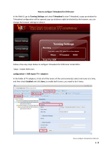
Enable Satellite Inputs
1. Click the Chassis tab (See Figure 8.) .
Figure 8. Chassis Tab - Enable Satellites
2. Under L-Band Inputs, click the check boxes in the Enable column. Check a box for each satellite connected
to the SMARTBOX satellite inputs (Sat ports 1-4).
3. Click the Apply button under the Enable column. If a message regarding disruption of satellite services
appears, click OK. (Cancel allows you to stop the process.) The status of the satellite discovery appears to
the right of the Apply and Undo buttons; the status may reflect Waiting, Not Ready, Ready or % Complete. It
takes approximately five minutes for the process to complete.
4. Click Export Transponder Information. This file will verify visibility of transponders on each applied
satellite feed. This file is updated when a satellite scan is run.
NOTES:
• RX Power indicates total satellite power — not individual transponders.
• The ideal signal range is between -20 dBm and -35 dBm, with each orbital being within ± 5 dBm of each other.
Larger dierences can result in intermittent performance. -62 dBm is the floor; if you see -62 dBm, there is no
signal being detected.
When deploying SMARTBOX at a customer’s site, take the following steps to ensure the orbital information is
correct.
1. Uncheck the satellite feeds then click Apply.
2. If the scan is stuck at “Waiting” or a specific percentage for more than 90 seconds, reboot the system.
a. If you have to reboot, when the system comes up you will see that the orbitals are still there, but
unchecked. Click Apply again.
3. Once all the feeds are unselected and no orbitals are listed, reselect the ones with connections then click
Apply.
4. Wait for that to complete, then confirm that all blades have tuner lock.

20
Verify Tuners Lock
1. Click the Blades tab (See Figure 9.).
2. Click the down-arrow under Details for the satellite blade.
3. Verify that one tuner in each set (tuner set 1-4 and tuner set 5-8) is locked. Examples of locked tuner pairs:
1 and 5, 4 and 5, 2 and 7.
If not locked, return to the Chassis tab and verify that the satellites have been enabled and click Apply again
and wait for the scan to complete. Return to the Blades tab and verify.
NOTES:
• Transcoder - When the Details on the Blades tab are expanded, you can see whether a transcoder is present
on the blade or not. A gray X indicates Not Present; a green check-mark indicates Present.
• Descrambling Status is located below the Tuner Information.
– “Granted” indicates the ProCam is authorized for service.
– “Denied” indicates the ProCam is not authorized.
– “Free” means the service does not require authorization and is free to all receivers.
– “SC Blackout” means service is blacked out due to programming agreements.
• Reset Blade button allows you to reboot the specific blade as opposed to rebooting the entire system (Admin
tab—> Reboot System button). If you attempt to reboot the master blade, an alert warning occurs indicating
that the system will lose connection until another blade becomes master or the blade comes back up.
• Disable Blade button removes the blade from available resources to assign services to. The blade is still
powered and visible in the interface, but no services will be assigned to it.
Figure 9. Locked Tuners
/