Harbor Freight Tools 7 in. x 12 in. Precision Benchtop Mini Lathe Owner's manual
- Category
- Lathes
- Type
- Owner's manual
This manual is also suitable for

7” X 12” MINI LATHE
Model 93799
ASSEMBLY AND OPERATING INSTRUCTIONS
3491 Mission Oaks Blvd., Camarillo, CA 93011
Visit our Web site at: http://www.harborfreight.com
Copyright
©
2006 by Harbor Freight Tools
®
. All rights reserved. No portion of this
manual or any artwork contained herein may be reproduced in any shape or form
without the express written consent of Harbor Freight Tools.
For technical questions, please call 1-800-444-3353.
®
Due to continuing improvements, actual product may differ slightly from the product described herein.

SKU 93799 For technical questions, please call 1-800-444-3353. Page 2
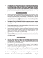
PRODUCT SPECIFICATIONS
Motor 3/4 Horsepower
Power Source 110V~, 60 Hz, Single Phase
Drive Gear and Belt
Swing Over Bed 7”
Distance Between Cen-
ters
12”
Spindle Bore 3/4”
Quill Travel 2”
Cross Slide Travel 2-3/4”
Cross Slide Swing 4-1/2”
Work Tolerance .005”
Bed Dimensions 19-7/8”L x 3-1/4” W
Saddle Travel 6-7/8”
Compound Travel 2-7/8”
Speed Ranges 0-1100 (low); 0-2500 (high)
Chuck Dimensions 80 mm; 3-jaw
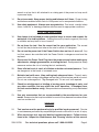
SAVE THIS MANUAL
You will need this manual for the safety warnings and precautions, assembly,
operating, inspection, maintenance and cleaning procedures, parts list and assembly
diagram. Keep your invoice with this manual. Write the invoice number on the inside
of the front cover. Keep manual and invoice in a safe place for future reference.
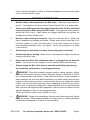
GENERAL SAFETY RULES
WARNING!
READ AND UNDERSTAND ALL INSTRUCTIONS
Failure to follow all instructions listed below may result in
electric shock, fire, and/or serious injury.
SAVE THESE INSTRUCTIONS
WORK AREA
1. Keep your work area clean and well lit. Cluttered benches and dark areas invite
accidents.
2. Do not operate power tools in explosive atmospheres, such as in the presence
of flammable liquids, gases, or dust. Power tools create sparks which may ignite
the dust or fumes.
3. Keep bystanders, children, and visitors away while operating a power tool.
Distractions can cause you to lose control. Protect others in the work area from
debris such as chips and sparks. Provide barriers or shields as needed.
Rev. 06/06; 03/07

SKU 93799 For technical questions, please call 1-800-444-3353. Page 3
4. Grounded tools must be plugged into an outlet properly installed and grounded
in accordance with all codes and ordinances. Never remove the grounding
prong or modify the plug in any way. Do not use any adapter plugs. Check with
a qualified electrician if you are in doubt as to whether the outlet is properly
grounded. If the tools should electrically malfunction or break down, grounding
provides a low resistance path to carry electricity away from the user.
ELECTRICAL SAFETY
5. Double insulated tools are equipped with a polarized plug (one blade is wider
than the other). This plug will fit in a polarized outlet only one way. If the plug
does not fit fully in the outlet, reverse the plug. If it still does not fit, contact
a qualified electrician to install a polarized outlet. Do not change the plug in
any way. Double insulation eliminates the need for the three wire grounded
power cord and grounded power supply system.
6. Avoid body contact with grounded surfaces such as pipes, radiators, ranges,
and refrigerators. There is an increased risk of electric shock if your body is
grounded.
7. Do not expose power tools to rain or wet conditions. Water entering a power
tool will increase the risk of electric shock.
8. Do not abuse the Power Cord. Never use the Power Cord to carry the tools or
pull the Plug from an outlet. Keep the Power Cord away from heat, oil, sharp
edges, or moving parts. Replace damaged Power Cords immediately. Dam-
aged Power Cords increase the risk of electric shock.
9. When operating a power tool outside, use an outdoor extension cord marked
“W-A” or “W”. These extension cords are rated for outdoor use, and reduce the
risk of electric shock.
PERSONAL SAFETY
10. Stay alert. Watch what you are doing, and use common sense when operat-
ing a power tool. Do not use a power tool while tired or under the influence
of drugs, alcohol, or medication. A moment of inattention while operating power
tools may result in serious personal injury.
11. Dress properly. Do not wear loose clothing or jewelry. Contain long hair.
Keep your hair, clothing, and gloves away from moving parts. Loose clothes,
jewelry, or long hair can be caught in moving parts.
12. Avoid accidental starting. Be sure the Power Switch is off before plugging
in. Carrying power tools with your finger on the Power Switch, or plugging in power
tools with the Power Switch on, invites accidents.
13. Remove adjusting keys or wrenches before turning the power tool on. A

SKU 93799 For technical questions, please call 1-800-444-3353. Page 4
wrench or a key that is left attached to a rotating part of the power tool may result
in personal injury.
14. Do not overreach. Keep proper footing and balance at all times. Proper footing
and balance enables better control of the power tool in unexpected situations.
15. Use safety equipment. Always wear eye protection. Dust mask, nonskid safety
shoes, hard hat, or hearing protection must be used for appropriate conditions.
TOOL USE AND CARE
16. Use clamps (not included) or other practical ways to secure and support the
workpiece to a stable platform. Holding the work by hand or against your body
is unstable and may lead to loss of control.
17. Do not force the tool. Use the correct tool for your application. The correct
tool will do the job better and safer at the rate for which it is designed.
18. Do not use the power tool if the Power Switch does not turn it on or off. Any
tool that cannot be controlled with the Power Switch is dangerous and must be
replaced.
19. Disconnect the Power Cord Plug from the power source before making any
adjustments, changing accessories, or storing the tool. Such preventive safety
measures reduce the risk of starting the tool accidentally.
20. Store idle tools out of reach of children and other untrained persons. Tools
are dangerous in the hands of untrained users.
21. Maintain tools with care. Keep cutting tools sharp and clean. Properly main-
tained tools with a sharp cutting edge are less likely to bind and are easier to control.
Do not use a damaged tool. Tag damaged tools “Do not use” until repaired.
22. Check for misalignment or binding of moving parts, breakage of parts, and
any other condition that may affect the tool’s operation. If damaged, have
the tool serviced before using. Many accidents are caused by poorly maintained
tools.
23. Use only accessories that are recommended by the manufacturer for your
model. Accessories that may be suitable for one tool may become hazardous when
used on another tool.
SERVICE
24. Tool service must be performed only by qualified repair personnel. Service
or maintenance performed by unqualified personnel could result in a risk of injury.
25. When servicing a tool, use only identical replacement parts. Follow instruc-
tions in the “Inspection, Maintenance, And Cleaning” section of this manual.

SKU 93799 For technical questions, please call 1-800-444-3353. Page 5
Use of unauthorized parts or failure to follow maintenance instructions may create
a risk of electric shock or injury.
SPECIFIC SAFETY RULES
1. Maintain labels and nameplates on the Mini Lathe. These carry important infor-
mation. If unreadable or missing, contact Harbor Freight Tools for a replacement.
2. Always wear ANSI-approved safety impact eye protection, full face shield and
heavy work gloves when using the Mini Lathe. Using personal safety devices
reduce the risk for injury. Safety impact eye goggles and heavy work gloves are
available from Harbor Freight Tools.
3. Maintain a safe working environment. Keep the work area well lit. Make sure
there is adequate surrounding workspace. Always keep the work area free of ob-
structions, grease, oil, trash, and other debris. Do not use a power tool in areas
near flammable chemicals, dusts, and vapors. Do not use this product in a damp
or wet location.
4. Always keep the extension cord away from moving parts on the tool.
5. Avoid unintentional starting. Make sure you are prepared to begin work before
turning on the Mini Lathe.
6. Never leave the Mini Lathe unattended when it is plugged into an electrical
outlet. Turn off the tool, and unplug it from its electrical outlet before leaving.
7. Always unplug the Mini Lathe from its electrical outlet before performing
any inspection, maintenance, or cleaning procedures.
8. WARNING! Some dust created by power sanding, sawing, grinding, drilling,
and other construction activities, contain chemicals known (to the State of Califor-
nia) to cause cancer, birth defects or other reproductive harm. Some examples of
these chemicals are: lead from lead-based paints, crystalline silica from bricks and
cement or other masonry products, arsenic and chromium from chemically treated
lumber. Your risk from these exposures varies, depending on how often you do this
type of work. To reduce your exposure to these chemicals: work in a well ventilated
area, and work with approved safety equipment, such as those dust masks that are
specially designed to filter out microscopic particles.
(California Health & Safety Code § 25249.5, et seq.)
9. WARNING! People with pacemakers should consult their physician(s) before
using this product. Electromagnetic fields in close proximity to a heart pacemaker
could cause interference to or failure of the pacemaker.

SKU 93799 For technical questions, please call 1-800-444-3353. Page 6
GROUNDING
WARNING!
Improperly connecting the grounding wire can result in the risk of electric shock.
Check with a qualified electrician if you are in doubt as to whether the outlet is
properly grounded. Do not modify the power cord plug provided with the tool.
Never remove the grounding prong from the plug. Do not use the tool if the
power cord or plug is damaged. If damaged, have it repaired by a service facil-
ity before use. If the plug will not fit the outlet, have a proper outlet installed by
a qualified electrician.
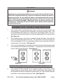
GROUNDED TOOLS: TOOLS WITH THREE PRONG PLUGS
1. Tools marked with “Grounding Required” have a three wire cord and three prong
grounding plug. The plug must be connected to a properly grounded outlet. If the
tool should electrically malfunction or break down, grounding provides a low resis-
tance path to carry electricity away from the user, reducing the risk of electric shock.
(See Figure A.)
2. The grounding prong in the plug is connected through the green wire inside the
cord to the grounding system in the tool. The green wire in the cord must be the
only wire connected to the tool’s grounding system and must never be attached to
an electrically “live” terminal. (See Figure A.)
3. Your tool must be plugged into an appropriate outlet, properly installed and grounded
in accordance with all codes and ordinances. The plug and outlet should look like
those in the following illustration. (See Figure A.)
FIGURE A FIGURE B
DOUBLE INSULATED TOOLS: TOOLS WITH TWO PRONG PLUGS
4. Tools marked “Double Insulated” do not require grounding. They have a special
double insulation system which satisfies OSHA requirements and complies with
the applicable standards of Underwriters Laboratories, Inc., the Canadian Standard
Association, and the National Electrical Code. (See Figure B.)

SKU 93799 For technical questions, please call 1-800-444-3353. Page 7
5. Double insulated tools may be used in either of the 120 volt outlets shown in the
preceding illustration. (See Figure B.)
EXTENSION CORDS
1. Grounded tools require a three wire extension cord. Double Insulated tools can
use either a two or three wire extension cord.
2. As the distance from the supply outlet increases, you must use a heavier gauge
extension cord. Using extension cords with inadequately sized wire causes a seri-
ous drop in voltage, resulting in loss of power and possible tool damage.
(See Figure C, next page.)
3. The smaller the gauge number of the wire, the greater the capacity of the cord. For
example, a 14 gauge cord can carry a higher current than a 16 gauge cord.
(See Figure C.)
4. When using more than one extension cord to make up the total length, make sure
each cord contains at least the minimum wire size required. (See Figure C.)
5. If you are using one extension cord for more than one tool, add the nameplate am-
peres and use the sum to determine the required minimum cord size.
(See Figure C.)
6. If you are using an extension cord outdoors, make sure it is marked with the suffix
“W-A” (“W” in Canada) to indicate it is acceptable for outdoor use.
7. Make sure your extension cord is properly wired and in good electrical condition.
Always replace a damaged extension cord or have it repaired by a qualified electri-
cian before using it.
8. Protect your extension cords from sharp objects, excessive heat, and damp or wet
areas.

SKU 93799 For technical questions, please call 1-800-444-3353. Page 8
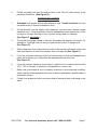
RECOMMENDED MINIMUM WIRE GAUGE FOR EXTENSION CORDS*
(120 OR 240 VOLT)
NAMEPLATE
AMPERES
(At Full Load)
EXTENSION CORD LENGTH
25 Feet 50 Feet 75 Feet 100 Feet 150 Feet
0 – 2.0 18 18 18 18 16
2.1 – 3.4 18 18 18 16 14
3.5 – 5.0 18 18 16 14 12
5.1 – 7.0 18 16 14 12 12
7.1 – 12.0 18 14 12 10 -
12.1 – 16.0 14 12 10 - -
16.1 – 20.0 12 10 - - -
FIGURE C
* Based on limiting the line voltage drop to five volts at
150% of the rated amperes.
SYMBOLOGY
Double Insulated
Canadian Standards Association
Underwriters Laboratories, Inc.
V~
Volts Alternating Current
A
Amperes
n
0
xxxx/min.
No Load Revolutions per Minute (RPM)

SKU 93799 For technical questions, please call 1-800-444-3353. Page 9
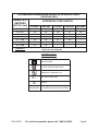
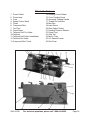
Unpacking
Carefully unpack the Mini Lathe and check all items. Figure 1 below shows all the
contents of the carton. Do not discard any packing material until the Mini Lathe is fully
assembled and operational. If any parts are missing or broken, please call Harbor Freight
Tools at 1-800-444-3353. Be sure you have all parts described in the parts listing at the
back of the manual.
Identification of Main Components
A. Lathe B. Chuck Key C. External Jaws
D. Chuck E. Chuck Set Screws F. Internal Jaws
Fig 1

SKU 93799 For technical questions, please call 1-800-444-3353. Page 10
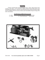
Mini Lathe Features
Power Switch
Power lamp
Fuse
Speed Control Knob
Chuck
Compound Rest
Tool Post
Fixed Center
Tailstock Quill Fix Holder
Tailstock
Tailstock Quill Adjust Handwheel
Tailstock Set Screw
Compound Rest Crank
1.
2.
3.
4.
5.
6.
7.
8.
9.
10.
11.
12.
13.
Feeding Control Wheel
Cross Feeding Crank
Automatic Feeding Handle
Thread Dial Indicator
Bed Way
Lead Screw
Rear Splash Guard
Feeding Direction Selector
Power Cord
Chip Tray
Motor Cover
H/L Gearshift Lever
End Cover
14.
15.
16.
17.
18.
19.
20.
21.
22.
23.
24.
25.
26.

SKU 93799 For technical questions, please call 1-800-444-3353. Page 11
Rev. 06/06
Adjusting the Mini Lathe
Clean off the protective grease on the Mini Lathe.
Check to see that the three set screws on the chuck are tight.
Turn the chuck by hand and check that it rotates freely.
Move the Feeding Direction Selector (located on the back of lathe) to the middle.
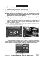
Make sure the Switch (#1 in figure 4 below) is at the OFF position.
WARNING: ADJUST THE SPEED CONTROL KNOB (#4) BY TURNING IT TO ZERO.
BEFORE TURNING ON THE MINI LATHE EACH TIME IT IS TO BE USED, THIS
SPEED CONTROL KNOB MUST BE AT ZERO.
Plug in the electrical cord and turn the Switch to the ON position and run the lathe
for 3 minutes. When the lathe is on, the Power Lamp (#2) will remain on. Check to
see that the lathe operates normally.
Check the Compound Rest Crank and the Cross Feeding Crank to see that they work
properly. If the cranks are too tight or too loose, turn the adjusting screws located at
both sides (see figure 5 below).
WARNING: THE MINI LATHE MUST BE COMPLETELY STOPPED BEFORE CHANG-
ING FORWARD/REVERSE DIRECTION.
Fig 4 Fig 5
2 1 4
Replacement of Chuck
When replacing the chuck, place a cloth or a piece of wood on the bedway at the
bottom of the chuck. This step will help avoid damage to the bedway caused by carelessly
dropping the chuck. To replace the chuck, loosen the 3 set screws as shown below.
1.
2.
3.
4.
5.
6.
7.

SKU 93799 For technical questions, please call 1-800-444-3353. Page 12
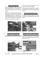
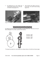
Replacement of Jaws
There are two types of jaws: the internal
jaws and external jaws. Please note that
the number of jaws fit with the number in-
side the chuck’s groove. Do not mix them
together.
When you are going to mount the jaws,
mount them in ascending order. When they
are taken out, make sure to take them out
in descending order (3-2-1) one by one. Af-
ter you finish this procedure, rotate the jaws
to the smallest diameter and check that the
three jaws are well fitted (see figure 7).
If the jaws do not fit well together, you will
need to reassemble them again.
When mounting a workpiece, it is recom-
mended that all three jaws are loosened at
the same time. This will protect the threads
inside.
Compound Rest Adjustment
To adjust the compound rest, loosen the
two screws as shown in figure 8 (A). After
adjusting to the required angle, tighten the
screws.
Tailstock Rest Adjustment
To change position or replace the tailstock,
loosen the nut as shown in (A) of figure 9.
Replacement of Carbon Brushes
To replace, remove brush covers on the
motor cover (A) in figure 10-A, and the right
bottom side of speed controller as shown in
(B) of figure 10-B.

SKU 93799 For technical questions, please call 1-800-444-3353. Page 13
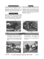
Tool Post Adjustment
Loosen the lever shown in (B) of figure 11,
the adjust the tool post position. Once the
adjustment is made, re-tighten the lever. To
replace the work cutter, loosen the screws
(A) with the hex key wrench provided.
Automatic Feeding
Adjust the feeding direction selector to the
direction you desire. Press down the handle
(A) in figure 12, and continue with the au-
tomatic feeding procedure. When feeding,
never try to change the feeding direction.
Threading
Select the feeding direction selector to the
thread direction desired. Then press down
handle (A) in figure 12 by matching the right
calibrations on the thread dial indicator (B)
and continue with the automatic threading
procedure. When threading, never try to
change the direction.
OPERATION
Use the chuck to hold the workpiece
firmly (figure 13 below). Then, use the
rolling center to fix the other end. If
you change the rolling center to drilling
chuck you start your drilling immedi-
ately.
1. Use the chuck to hold the workpiece
firmly and cutter to start lathe’s face
cutting (figure 14). The edge of the
cutter must be at the same height as
the center.
2.

SKU 93799 For technical questions, please call 1-800-444-3353. Page 14
C
D
A
B
By changing the tool post angle and
adjusting the compound rest, you can
do internal cutting (figure 15).
3. After adjusting the angle of the com-
pound rest, you can do bevel cutting
(figure 16).
4.
Setup Instructions for Threading Gears
By changing the gear set-up it is possible to cut any thread size. The factory set-up for
Mini Lathe gears is as follows (see illustration below):
To change the thread size, use the gear box settings shown on the table on the next page.
B
D
A
C
Position A= 20T
Position B= 80T
Position C= 20T
Position D= 80T
Fig 15 Fig 16

SKU 93799 For technical questions, please call 1-800-444-3353. Page 15
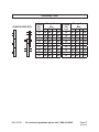
Threading Chart
Rev. 06/06
Thread
Per
Inch
Change Gear
Box
A B C D
12 40 65 / 30
13 40 65 60 30
14 40 65 / 35
16 40 65 / 40
18 40 65 / 45
19 40 50 60 57
20 40 65 / 50
22 40 65 / 55
24 40 65 / 60
Thread
Per
Inch
Change Gear
Box
A B C D
26 40 60 / 65
28 20 65 / 35
32 20 65 / 40
36 20 65 / 45
38 20 60 60 57
40 20 65 / 50
44 20 65 / 55
48 20 65 / 60
52 20 60 / 65
C
D
A
B
D
A
B
CHANGE GEAR BOX

SKU 93799 For technical questions, please call 1-800-444-3353. Page 16
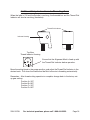
Additional Setup Instructions for Threading Gears
When the lathe is ON and the Spindle is revolving, the threaded bar and the Thread Dial
Indicator will also be revolving (see below).
Ensure that the Alignment Mark is lined up with
the Thread Dial Indicator before operation.
Move the cutting blade to the proper position, and adjust theThread Dial Indicator to the
desired mark. Pull down the Handle and the Mini Lathe starts threading automatically.
Remember: After thread cutting operation is complete, change back to the factory set-
up gear setting:
Position A= 20T
Position B= 80T
Position C= 20T
Position D= 80T
Top View
Thread Indicator Housing
Thread Dial Indicator
Indicator Housing

SKU 93799 For technical questions, please call 1-800-444-3353. Page 17

SKU 93799 For technical questions, please call 1-800-444-3353. Page 18

SKU 93799 For technical questions, please call 1-800-444-3353. Page 19

SKU 93799 For technical questions, please call 1-800-444-3353. Page 20
Page is loading ...
Page is loading ...
Page is loading ...
-
 1
1
-
 2
2
-
 3
3
-
 4
4
-
 5
5
-
 6
6
-
 7
7
-
 8
8
-
 9
9
-
 10
10
-
 11
11
-
 12
12
-
 13
13
-
 14
14
-
 15
15
-
 16
16
-
 17
17
-
 18
18
-
 19
19
-
 20
20
-
 21
21
-
 22
22
-
 23
23


Harbor Freight Tools 7 in. x 12 in. Precision Benchtop Mini Lathe Owner's manual
- Category
- Lathes
- Type
- Owner's manual
- This manual is also suitable for
Ask a question and I''ll find the answer in the document
Finding information in a document is now easier with AI
Related papers
-
Harbor Freight Tools 92188 User manual
-
 Pittsburgh 41146 User manual
-
-
Bunker Hill Security 95318 Owner's manual
-
-
-
Central Machinery 93212 User manual
-
-
Harbor Freight Tools 33684 User manual
-

Other documents
-
Chicago Electric 96996 User manual
-
King Canada KC-0712ML User manual
-
-
-
 Master Quality Power MW40018 User manual
-
-
-
 Gear Head Lathe 65044 User manual
-
-

