Page is loading ...

Apollo
Model SL30 NAV/COMM
Installation Manual
August 2003
560-0404-03a

2003 Garmin AT, Inc. All rights reserved.
Printed in the USA
No part of this document may be transmitted, reproduced, or copied in any form or by any means
without the prior written consent of Garmin AT, Inc. Due to Garmin AT’s commitment to
constantly improve the quality and performance of our products, information contained in this
document is subject to change without notice.
Garmin AT, Inc. and Apollo are registered trademarks of Garmin AT, Inc.
Garmin AT, Inc. 2345 Turner Rd. SE
PO Box 13549 Salem, OR 97302
Salem, OR 97309 USA
Phone 503.581.8101
800.525.6726
In Canada 800.654.3415
Fax: 503.364.2138

HISTORY OF REVISIONS
Revision Date Description
-- 11/16/99 Initial release (EN6278).
01 2/10/00 Added interface wiring diagrams, refined post installation
checkout procedures.
02 8/2/01 New mounting tubes, dual SL30’s, DST info to Apollo GX (EN
6949). SW Version 1.2
03 2/21/02 Added helicopter environmental qualification information.
03a 8/26/03 Changed logo and added JTSO information.
IMPORTANT NOTE
“The conditions and tests required for TSO approval of this article are minimum performance
standards. It is the responsibility of those desiring to install this article on or within a specific
type or class of aircraft to determine that the aircraft operating conditions are within TSO
standards. The article may be installed only if further evaluation by the applicant documents
an acceptable installation and is approved by the Administrator.” Follow installation
recommendations as noted in AC20-67B, Airborne VHF Communications Equipment
Installations.
Source: FAA TSO-C34e, TSO-C36e, TSO-C37d, TSO-C38d, TSO-
C40c, TSO-C66c, and TSO-C128.
ORDERING INFORMATION
To receive additional copies of this publication, order part # 560-0404-03a, Apollo SL30
NAV/ COMM Installation Manual.
REFERENCE PUBLICATIONS
Following are other publications referenced in this guide.
Apollo SL30 NAV/ COMM Operation Manual, order part # 560-0403-xx.

NOTES

Table of Contents
Apollo SL30 Installation Manual
i
TABLE OF CONTENTS
SECTION 1 - INTRODUCTION ................................................................................................ 1
A
BOUT THIS MANUAL ..................................................................................................................... 1
A
POLLO SL30 DESCRIPTION ............................................................................................................ 1
FEATURES ........................................................................................................................................ 2
GENERAL FEATURES ..................................................................................................................................................2
NAVIGATION RADIO FEATURES .................................................................................................................................2
COMM RADIO FEATURES ...........................................................................................................................................3
PHYSICAL SPECIFICATIONS ........................................................................................................................................3
NAV RADIO PERFORMANCE SPECIFICATIONS ...........................................................................................................3
COMM RADIO PERFORMANCE SPECIFICATIONS..........................................................................................................3
SYSTEM INTERFACES........................................................................................................................ 4
NAVIGATION RECEIVER .............................................................................................................................................4
COMM TRANSCEIVER.................................................................................................................................................4
SERIAL INTERFACE ....................................................................................................................................................4
REGULATORY COMPLIANCE............................................................................................................. 4
UNPACKING THE EQUIPMENT ........................................................................................................... 5
PACKAGE CONTENTS ....................................................................................................................... 5
OTHER REQUIRED MATERIALS......................................................................................................... 6
SPECIAL TOOLS REQUIRED............................................................................................................... 6
LICENSE REQUIREMENTS ................................................................................................................. 7
SECTION 2 - INSTALLATION.................................................................................................. 9
PRE-INSTALLATION INFORMATION................................................................................................... 9
INSTALLATION OVERVIEW ............................................................................................................... 9
INSTALLATION CONSIDERATIONS..................................................................................................... 9
MOUNTING CONSIDERATIONS....................................................................................................................................9
MINIMUM SYSTEM CONFIGURATION..........................................................................................................................9
EQUIPMENT MOUNTING ................................................................................................................. 10
MOUNTING TUBE INSTALLATION .............................................................................................................................10
UNIT INSERTION.......................................................................................................................................................12
UNIT REMOVAL .......................................................................................................................................................12
E
LECTRICAL CONNECTIONS ........................................................................................................... 14
POWER .....................................................................................................................................................................14
AVIONICS OUTPUTS .................................................................................................................................................14
SERIAL INTERFACE ..................................................................................................................................................14
SPEAKER AND HEADPHONE OUTPUTS ......................................................................................................................14
MICROPHONE INPUTS...............................................................................................................................................15
TRANSMIT KEY INPUT..............................................................................................................................................15
INTERCOM SELECTOR SWITCH .................................................................................................................................15
REMOTE FLIP/FLOP INPUT........................................................................................................................................15
ANTENNA INSTALLATION AND CONNECTIONS ............................................................................... 15
COMM AND NAV ANTENNAS....................................................................................................................................15
USE OF SPLITTER AND COMBINER............................................................................................................................16
EQUIPMENT INTERFACE ................................................................................................................. 17
L
IMITATIONS ON USING A COMPOSITE SIGNAL .............................................................................. 33
LIMITATIONS ON DISTANCE, SPEED, AND TIME INFORMATION....................................................... 33
P
OST INSTALLATION CHECKOUT.................................................................................................... 33
MOUNTING / WIRING CHECK ...................................................................................................................................33

Table of Contents
ii Apollo SL30 Installation Manual
SETUP AND CHECKOUT............................................................................................................................................ 33
FINAL SYSTEM CHECK ............................................................................................................................................ 37
INSTRUCTIONS FOR CONTINUED AIRWORTHINESS ..........................................................................40
SECTION 3 - SPECIFICATIONS .............................................................................................41
ELECTRICAL ...................................................................................................................................41
PHYSICAL .......................................................................................................................................41
ENVIRONMENTAL ...........................................................................................................................41
AVIONICS OUTPUTS ........................................................................................................................42
NAV RECEIVER PERFORMANCE .....................................................................................................43
VOR ....................................................................................................................................................................... 43
LOCALIZER.............................................................................................................................................................. 43
GLIDESLOPE ............................................................................................................................................................ 44
OBS RESOLVER ...................................................................................................................................................... 44
COMPOSITE OUTPUT................................................................................................................................................ 44
COMM RECEIVER PERFORMANCE ...................................................................................................45
COMM TRANSMITTER PERFORMANCE.............................................................................................45
INTERCOM PERFORMANCE ..............................................................................................................46
CONTROL INPUTS............................................................................................................................46
ANTENNA REQUIREMENTS..............................................................................................................46
COMM ANTENNA..................................................................................................................................................... 46
NAV ANTENNA....................................................................................................................................................... 46
SERIAL INTERFACE .........................................................................................................................47
REAR CONNECTOR PINOUT.............................................................................................................47
SECTION 4 - LIMITATIONS ...................................................................................................49
INSTALLATION ................................................................................................................................49
COMPUTATION RATES ....................................................................................................................49
OPERATIONAL.................................................................................................................................49
APPENDIX A - TROUBLESHOOTING ..................................................................................51
CONTACTING THE FACTORY FOR ASSISTANCE................................................................................52
APPENDIX B - PERIODIC MAINTENANCE ........................................................................53
VOR CHECKS .................................................................................................................................53
E
QUIPMENT CALIBRATION..............................................................................................................53
REFERENCE OSCILLATOR (COMM ONLY) ................................................................................................................ 53
CLEANING THE FRONT PANEL.........................................................................................................53
APPENDIX C - ENVIRONMENTAL QUALIFICATIONS...................................................55
APPENDIX D - ACCESSORIES ...............................................................................................57
F
ROM GARMIN AT, INC. .................................................................................................................57
APPENDIX E - SERIAL INTERFACE SPECIFICATIONS .................................................59
I
NPUT COMMANDS..........................................................................................................................59
OUTPUT MESSAGES ........................................................................................................................59
D
ATA FORMAT................................................................................................................................60
D
EFAULT MESSAGE OUTPUT ..........................................................................................................60
MESSAGE FORMATS........................................................................................................................60

Table of Contents
Apollo SL30 Installation Manual
iii
MESSAGE DEFINITIONS .................................................................................................................. 61
INPUT MESSAGES.....................................................................................................................................................61
REMOTE VOR LIST..................................................................................................................................................62
REMOTE LOCALIZER LIST ........................................................................................................................................64
REQUEST DATA OUTPUT..........................................................................................................................................66
SET ACTIVE VOR/LOC FREQUENCY AND RECEIVER FUNCTION .............................................................................67
SET STANDBY VOR/LOC FREQUENCY AND RECEIVER FUNCTION ..........................................................................67
SET STANDBY COMM FREQUENCY AND TRANSCEIVER FUNCTION.........................................................................68
SET ACTIVE COMM FREQUENCY AND TRANSCEIVER FUNCTION............................................................................68
SET NAV AUDIO MODE...........................................................................................................................................69
SET OMNI-BEARING SELECT (OBS) VALUE.............................................................................................................69
DME SENSOR INPUT................................................................................................................................................70
OUTPUT MESSAGES........................................................................................................................ 70
RESET STATUS .........................................................................................................................................................70
CDI, GSI, AND RELATED FLAGS..............................................................................................................................71
DECODED OBS SETTING ..........................................................................................................................................72
RADIAL FROM ACTIVE VOR....................................................................................................................................72
RADIAL FROM STANDBY VOR ................................................................................................................................72
DECODED STATION IDENTIFIER................................................................................................................................73
COMMUNICATIONS ERROR.......................................................................................................................................73
NAV RECEIVER STATUS..........................................................................................................................................74
NAV AUDIO MODE .................................................................................................................................................74
NAV MICROCONTROLLER SOFTWARE VERSION......................................................................................................75
NAV DSP SOFTWARE VERSION ..............................................................................................................................75
ADC DATA OUTPUT ................................................................................................................................................75
COMM TRANSCEIVER STATUS..................................................................................................................................76
COMM SOFTWARE VERSION.....................................................................................................................................76

Table of Contents
iv Apollo SL30 Installation Manual
LIST OF TABLES
TABLE 1 - PACKAGE CONTENTS........................................................................................................5
TABLE 2 - COMM INTERFACE CONNECTOR PINOUT ........................................................................47
T
ABLE 3 - REAR PANEL CONNECTOR PINOUT .................................................................................48
T
ABLE 4 - TROUBLESHOOTING GUIDE ............................................................................................51
TABLE 5 - DATA OUTPUT REQUESTS ..............................................................................................66
LIST OF ILLUSTRATIONS
FIGURE 1 - SL30 FRONT PANEL ........................................................................................................2
F
IGURE 2 - FULL STACK MOUNTING TUBE SPACING.......................................................................11
FIGURE 3 - CAM LOCK POSITIONING...............................................................................................12
F
IGURE 4 - MOUNTING FRAME ASSEMBLY .....................................................................................13
F
IGURE 5 - CABLE ROUTING ...........................................................................................................13
F
IGURE 6 - REAR COAX CONNECTOR ASSEMBLY ...........................................................................16
FIGURE 7 - SL30 COMM WIRING DIAGRAM ....................................................................................18
FIGURE 8 - SL30 COMM TYPICAL AUDIO PANEL CONNECTIONS ....................................................19
FIGURE 9 - SL30 NAV POWER AND AUDIO CONNECTIONS ............................................................20
FIGURE 10 – SL30 TO APOLLO GX50/60 CONNECTIONS ................................................................20
FIGURE 11 - SL30 - GX50/60 - MX20 CONNECTIONS ....................................................................21
FIGURE 12 - SL30 NAV TO MID-CONT MD200-306/307...............................................................22
FIGURE 13 - SL30 NAV TO MID-CONT MD200-302/303 CONNECTIONS .......................................23
FIGURE 14 - SL30 NAV AND ACU TO MID-CONT MD200-306/307..............................................24
FIGURE 15 - SL30 NAV TO STEC IND-351A CONNECTIONS ........................................................25
FIGURE 16 - SL30 NAV TO BENDIX/KING KN72/203/204/208/208A/209/209A WIRING .............26
FIGURE 17 - SL30 NAV TO BENDIX/KING KI202/206/525A/KPI552 WIRING...............................27
FIGURE 18 - SL30 NAV TO SANDEL DISCRETE CONNECTIONS.......................................................28
FIGURE 19 - SL30 NAV TO SANDEL SN3308 CONVERTER CONNECTIONS .....................................29
FIGURE 20 - SL30 TO SPERRY RD 550A AND RD650 WIRING .......................................................30
F
IGURE 21 - SL30 TO COLLINS 331A-6P, 331A-9G, AND PN-101 WIRING ....................................31
F
IGURE 22 - SL30 TO CENTURY NSD 360A AND NSD 1000 WIRING.............................................32
FIGURE 23 - UNIT DIMENSIONS.......................................................................................................42

Introduction
Apollo SL30 Installation Manual
1
SECTION 1 - INTRODUCTION
ABOUT THIS MANUAL
This manual describes the installation of the Apollo SL30 Nav/Comm units. It is intended for
use by persons certified by the Federal Aviation Administration (FAA) to install aircraft
navigation devices. It includes installation and checkout procedures for the SL30 unit to
standards described in FAA advisory circulars AC 20-67B (for Comm).
Provides an introduction to the Apollo SL30 unit. TSO certification information
is also included in this section.
Includes installation and checkout procedures.
Includes complete specifications.
Includes limitations for the equipment and installation.
Includes troubleshooting information.
Includes periodic maintenance requirements.
Includes the environmental qualification form.
Includes information on accessories.
Includes serial data specifications.
APOLLO SL30 DESCRIPTION
The Apollo SL30 includes a 760-channel VHF Comm transceiver and 200-channel
VOR/LOC/GS navigation receiver with DME display.
The Apollo SL30 is a member of the Apollo slimline series which includes the SL10/15
Audio Selector Panels, SL40 Comm, SL50 GPS, SL60 GPS/Comm, and SL70 Transponder.
Section 1
Section 2
Section 3
Section 4
Appendix A
Appendix B
Appendix C
Appendix D
Appendix E
Introduction
2 Apollo SL30 Installation Manual
FEATURES
GENERAL FEATURES
• 32 character high-intensity alphanumeric LED display
• Sunlight readable full alphanumeric display
• Automatic display intensity
• Back-lit buttons
• 200 channel memory (stored alphabetically)
• Remote frequency flip-flop input pin
NAVIGATION RADIO FEATURES
• 200 channel Nav with solid state DSP technology
• VOR/Localizer and Glideslope receivers
• Built-in VOR/Localizer converter
• Frequency range: VOR 108.00 – 117.95 MHz
Localizer 108.00 – 111.95 MHz
Glideslope 328.60 – 335.40 MHz
• Digitally decoded OBS setting
• Manual selection of back course approach
• Automatic display of station ID by decoding Morse code
• Interfaces to most CDI (w/resolver), HSI, and autopilot systems
• VOR receiver displays To or From radial of the active channel
• VOR monitor displays From radial of the standby channel
• Back course annunciator output
• LOC enable annunciator output
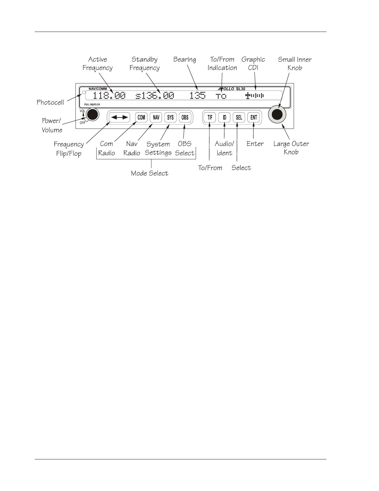
Figure 1 - SL30 Front Panel

Introduction
Apollo SL30 Installation Manual
3
• Internal RF diplexor
• Active and standby flip/flop frequencies
• DME tuning and data display
COMM RADIO FEATURES
• 760 communications channels
• Frequency range 118 to 136.975 MHz
• Active and standby flip/flop frequencies
• Volume control
• Tunes to National Weather Service broadcasts
• Transmit status indicator
• Frequency monitor function (listens to standby while monitoring active)
• Emergency channel menu
• Squelch test function
• Stuck Mic time-out
• 12 watt audio amplifier
• Includes two-place VOX intercom
PHYSICAL SPECIFICATIONS
• 1.3"(H) x 6.25" (W) x 10.5" (D)
• Weight 2.25 lbs. (unit only)
• Depth 11.452 inches (29.09cm) behind panel, including mounting frame and connectors
NAV RADIO PERFORMANCE SPECIFICATIONS
• Input voltage range 10 to 40 VDC
• Operating temperature range –20ºC to +55ºC
• Certified TSO C34e/JTSO C34e (Glideslope receive)
• Certified TSO C36e/JTSO C36e (ILS Localizer receive)
• Certified TSO C40c/JTSO 2C40c (VOR receive)
• Certified TSO C66c/JTSO 2C66b (DME display)
COMM RADIO PERFORMANCE SPECIFICATIONS
• Input voltage range 10 to 40 VDC
• Operating temperature range –20ºC to +55ºC
• Transmit power 8 watts (Carrier Power)
• Certified TSO C37d/JTSO 2C37e (Comm transmitting)
• Certified TSO C38d/JTSO 2C38e (Comm receiving)
• Certified TSO C128/JTSO 2C128 (stuck mic)

Introduction
4 Apollo SL30 Installation Manual
SYSTEM INTERFACES
NAVIGATION RECEIVER
The SL30 can be installed in several configurations based upon individual requirements. This
includes with or without an external course deviation indicator. The CDI may be discrete,
serial, or composite.
COMM TRANSCEIVER
For standalone installations, the Comm requires connections to:
• a standard Comm antenna
• a microphone (or microphones)
• a speaker or headphone
• power input
These items may be installed dedicated to the SL30 Comm, or by connection to an audio
panel. The system can be configured to mix the NAV audio with the Comm audio if no
external audio panel is used.
SERIAL INTERFACE
• DME – Distance Measure Equipment
• SL/GX – GPS products
• MX – Multi-Function Display
REGULATORY COMPLIANCE
The Apollo SL30 is designed and tested to meet the following TSOs/JTSOs:
FAA TSO-C37d/JTSO 2C37e for Comm transmit
FAA TSO-C38d/JTSO 2C38e for Comm receive
FAA TSO-C128/JTSO 2C128 for unintentional transmission (stuck mic)
FAA TSO-C34e/JTSO C34e for ILS Glideslope receive
FAA TSO-C36e/JTSO C36e for ILS Localizer receive
FAA TSO-C40c/JTSO 2C40c for VOR receive
FAA TSO-C66c/JTSO 2C66b for DME display
The Apollo SL30 complies with the FCC requirements specified in:
CFR 47, Part 87, Aviation Services, Subpart D, Technical Requirements
The Apollo SL30 complies with the FCC requirements specified in:
CFR 47, Part 15, Radio Frequency Devices, Subpart B, Unintentional Radiators
The Apollo SL30 software is designed and tested to RTCA/DO-178B, level C and ED-12B,
level C.
Note: Unauthorized changes or modifications to the SL30 may void the
compliance to required regulatory agencies and authorization for continued
equipment usage.

Introduction
Apollo SL30 Installation Manual
5
UNPACKING THE EQUIPMENT
Carefully unpack the equipment. Visually inspect the package contents for any evidence of
shipping damage. Retain all shipping containers and packaging material in case reshipment is
necessary.
PACKAGE CONTENTS
As shipped from the Garmin AT factory, the Apollo SL30 package includes most items
necessary for installation other than supplies normally available at the installation shop, such
as wire and cable ties, and required input and output equipment. The standard items included
in the package are listed in Table 1.
Table 1 - Package Contents
Part # Description Qty
430-6040-3xx SL30 NAV/COMM 1
Install kits Part number: 424-2006-300
162-1575 15-pin d-sub connector shell 1
162-1577 37-pin d-sub connector shell 1
162-1008 Right angle coax plug 2
202-0001 Cable tie 2
204-0037 Edge grommet 6"
204-2100 Shoulder bushing 4
221-0400 4-40 x 1/4 SS pan head Phillips machine screw with lock
washer
8
224-0404 4-40 x 1/4 SS flat head Phillips machine screw 4
245-0027 Crimp contact for d-sub, 20 to 24 awg wire 50
310-5181-xx or
310-5197-xx
Mounting frame
NOTE: Only 310-5197-xx is qualified for helicopter use.
1
310-5192-xx Connector mounting plate 1
998-0048 3/32 hex driver 1
Manual kits Part number: 564-0064-300 -4xx
560-0403-xx SL30 User’s Manual 1
560-0404-xx SL30 Installation Manual 1
561-0262-xx SL30 Quick Reference Guide 1
Accessories
115-0007 NAV signal splitter/combiner Optional
S712-0007-012 Internal 3 amp slow blow fuse Optional
Note: Package contents may vary depending on how the unit is ordered.

Introduction
6 Apollo SL30 Installation Manual
OTHER REQUIRED MATERIALS
The SL30 is intended for use with standard aviation accessories. External devices required for
various installations are listed below. Depending upon the installation, this will include items
such as:
• back course annunciator
• a CDI or HSI
• a Comm antenna
• NAV antenna
• NAV antenna splitter (if dual SL30)
• a microphone(s)
• a speaker or headphone
• audio panel
SPECIAL TOOLS REQUIRED
Crimp Tool
A crimp tool meeting MIL specification M22520/1-01 and a positioner/locater are required to
ensure consistent, reliable crimp contact connections for the rear 15-pin and 37-pin
connectors. These tools are available from:
For pin P/N 245-0022
Astro Tool Corp. Phone (503) 642-9853
21615 SW TV Highway Fax (503) 591-7766
Beaverton, OR 97006
Crimp tool: Astro Tool part #615708
Positioner: Astro Tool part #616356
For pin P/N 245-0027
ITT Cannon Phone (714) 261-5300
1851 E. Deere Ave. Fax (714) 575-8324
Santa Ana, CA 92705-6500
Insertion tool: ITT part # 274-7006-000 (Desc. CIET-20HD)
Regular duty Crimp tool: ITT part #995-0001-585 (Desc. M22520/1-01)
Regular duty Locator tool: ITT part #995-0001-244 (Desc. TH25)
Heavy duty Crimp tool: ITT part #995-0001-584 (Desc. M22520/2-01)
Heavy duty Locator tool: ITT part #995-0001-604 (Desc. M22520/2-08)

Introduction
Apollo SL30 Installation Manual
7
LICENSE REQUIREMENTS
An aircraft radio station license may be required for operation of the SL30 Comm transmitter
once installed in the aircraft. An application must be submitted on FCC Form 404, Form 605
or later revised application, which may be obtained from the FCC in Washington, DC, or any
of its field offices. Procedures for applications are in CFR 47, Part 87, Aviation Services,
Subpart B, Applications and Licenses.

Introduction
8 Apollo SL30 Installation Manual
NOTES

Installation
Apollo SL30 Installation Manual
9
SECTION 2 - INSTALLATION
This section describes the installation of the SL30 including mounting, wiring, and
connections. A post installation check-out procedure is included at the end of this section.
PRE-INSTALLATION INFORMATION
Always follow good avionics installation practices per FAA Advisory Circulars (AC) 43.13-
1B, 43.13-2A, and AC 20-67B, or later FAA approved revisions of these documents.
Follow the installation procedure in this section as it is presented for a successful installation.
Read the entire section before beginning the procedure. Perform the post installation check-
out before closing the work area in case problems occur.
INSTALLATION OVERVIEW
A successful installation should start with careful planning including determination of
mounting location for the SL30, antenna mounting, connections to microphones, speakers,
and headphones, cable routing, and other required modifications. Once the mounting location
has been determined, prepare the mounting frame for installation. It may be easier to complete
the wiring harness and attach the connectors to the mounting frame before installing the
mounting frame.
INSTALLATION CONSIDERATIONS
MOUNTING CONSIDERATIONS
The SL30 is designed to mount in the avionics stack in the aircraft instrument panel within
easy view and reach of the pilot. The standard package includes a mounting frame for ease of
mounting, connections, and service of the unit. Allow an additional one-inch clearance to the
rear of the mounting frame for connectors and cables.
For typical installations, the SL30 does not require external cooling. When mounting the unit,
leave a clearance of 1/8 to 1/4 inch between avionics to allow for air circulation.
MINIMUM SYSTEM CONFIGURATION
VFR Installation
VFR installation need only include an SL30 with power, audio, and antenna connections.
Without an external CDI, no glideslope information is obtainable. However, the unit will
maintain full VOR and Localizer functionality including an internal CDI display.
IFR VOR/LOC Installation
IFR installation requires:
• SL30
• External CDI/HSI indicator that meets the following criteria:
1. The course deviation indicator shall have an input impedance of 1 k ohm ± 10% and a
deflection sensitivity of 150 mV ± 10% for full scale deflection.
2. The valid flag shall have an input impedance of 1 k ohms ± 10%.

Installation
10 Apollo SL30 Installation Manual
3. The valid flag sensitivity shall be 125 mV ± 10% for the flag to leave the stop and
260 mV ± 10% maximum for flag to be fully concealed.
4. The To/From flag shall have an input impedance of 200 ohms ± 10% and a sensitivity
of ± 40 mV ± 15% at 25
o
C with flag fully in view.
5. The OBS resolver should be compatible with a standard 6-wire OBS interface:
H ...........Reference output high
C............Reference output low
D ...........S1 COS input high
E............S3 COS input low
F ............S4 SIN input high
G ...........S2 SIN input low
Any electrical zero crossing will work because the SL30 will calibrate out any errors.
Glideslope Installation
Glideslope installation requires:
• SL30
• External non-numeric glideslope indicator that meets the following criteria:
1. The glideslope deviation shall have an input impedance of 1 k ohm ± 10% with a
deflection sensitivity of 150 mV ± 10% for full scale deflection.
2. The glideslope valid flag shall have an input impedance of 1 k ohm ± 10%.
3. The glideslope valid flag sensitivity shall be 125 mV ± 10% for the flag to leave the
stop, and 260 mV ± 10% maximum for flag to be fully concealed.
Helicopter Requirements
The SL30 is qualified for helicopter installation with certain mount tube and SL
configurations (see Section 4 – Limitations).
EQUIPMENT MOUNTING
Once the cable assemblies have been made, attach the 15- and 37-pin d-sub and coaxial cable
connectors to the rear connector mounting plate and the mounting frame as illustrated in
Figure 4 and Figure 5. Route the wiring bundle as appropriate. The rear connector plate
should be attached to the mounting frame before installing the frame in the instrument panel.
The rear connector plate can be used to tie down the cable assemblies. Use the supplied edge
guard to protect the cable from sharp edges. Connect the shield grounds directly to the
connector mounting plate.
Once the cable assemblies are complete and the connectors are attached to the mounting
frame, install the mounting frame assembly in the instrument panel as illustrated in Figure 2.
Be sure to use low-profile head screws in the side of the mounting frame so the unit will slide
in and out freely. Attach the front of the mounting frame to the instrument panel. Use support
brackets to attach the rear of the frame to the aircraft.
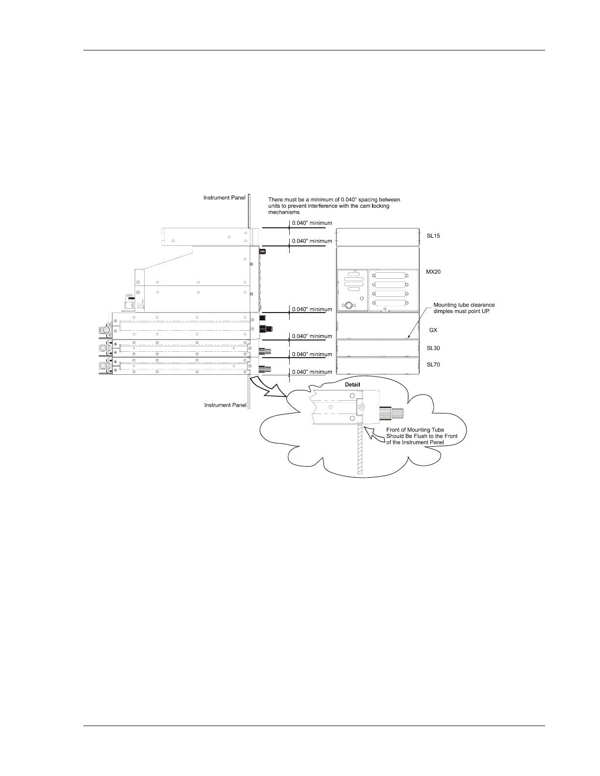
MOUNTING TUBE INSTALLATION
Care must be taken when installing the mounting tube to ensure you can properly insert and
secure the unit. There must be a minimum vertical spacing of 0.040 inches between units to
prevent interference with the cam locking mechanisms. Mounting tubes with clearance
Installation
Apollo SL30 Installation Manual
11
dimples help maintain the proper clearance. The mounting tube must be installed with the
clearance dimples pointing up.
The mounting tube should be flush to the instrument panel and allow sufficient clearance for the
back of the bezel of the unit to mount flush to the mounting tube. Sufficient clearance must exist
in the instrument panel opening to allow ease of insertion and removal of the unit. If the back
of the unit bezel does not mount flush to the mounting tube, the connector may not
engage fully.
Figure 2 - Full Stack Mounting Tube Spacing
Secure the mounting tube to the instrument panel structure. Mounting screw heads must not
protrude into the mounting tube. Be sure to use the appropriate screws so the unit will slide in
and out freely. The screws attaching the mounting tube to the instrument panel structure must
not interfere with the insertion of the unit. Failure to prevent interference will result in
damage to the unit or prevent its insertion. Take care that the mounting tube is not distorted
when it is attached to the instrument panel and structural supports. Shims may be necessary to
properly install the mounting tube. If the mounting tube is distorted out of square, the unit may
either bind when being inserted or the cam lock may not engage.
Installation
12 Apollo SL30 Installation Manual
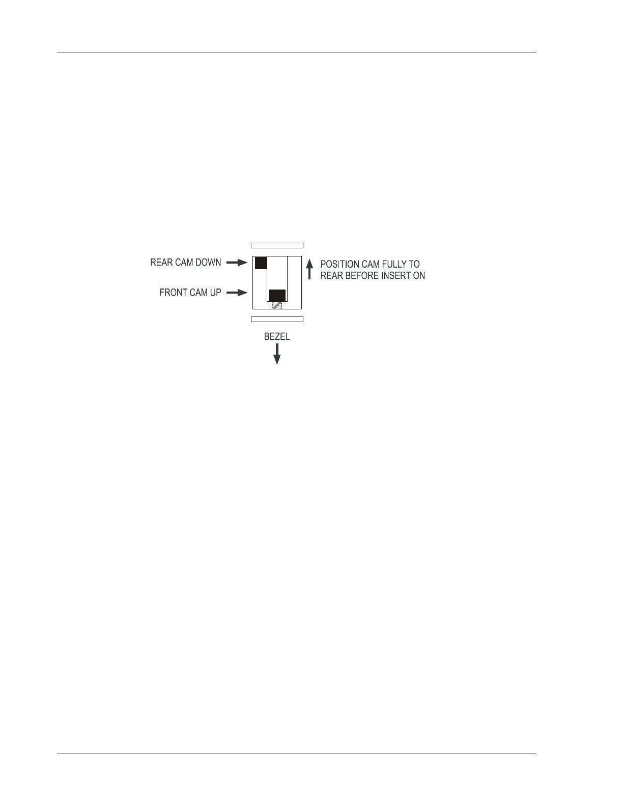
UNIT INSERTION
Position the cam lock as shown below. The front lobe of the cam should be vertical. The cam
lock mechanism should be fully unscrewed (turned counter-clockwise). Slide the unit into the
frame. Turn (clockwise) and carefully hand-tighten (4 in-lb max.) the cam lock mechanism
using only the 3/32" hex driver provided in the installation package. Using a larger tool than
the one provided makes it easy to exceed the allowable torque on the cam lock resulting in
damage to the unit. The unit will be pulled into the frame securing the unit and the connectors
when fully engaged. Do NOT overtighten. The back of the bezel must be flush to the
mounting tube. If the cam lock is hard to turn or the unit does not seat fully, the unit is
probably binding and the mounting tube should be checked.
Figure 3 - Cam Lock Positioning
UNIT REMOVAL
To remove the unit from the mounting frame, turn the screw counter-clockwise with the hex
driver to unscrew the cam lock mechanism. The unit will begin to pull away from the
mounting tube. Turn the screw until slight resistance is felt and then pull the unit from the
frame. Do not exert excessive turning force at the end of the cam lock travel or the unit
may be damaged. With the cam lock fully disengaged, pull the unit straight out holding onto
the sides of the bezel. It is not recommended that you pull the unit out by the rotary knobs. No
special extraction tools are required, if the mounting tube is properly installed.
/