Page is loading ...

CONTROLLED ENVIRONMENT
CHAMBER
Model 5532
Operating Manual
3/07
www/electrotechsystems.com

TABLE OF CONTENTS
1.0 MODEL 5532 CONTROLLED ENVIRONMENT CHAMBER 1
1.1 Chamber Controllers & Operating Systems 1
1.1.1 Front Panel Description 3
1.1.2 Side Interface Panel Description 5
1.1.3 Operating Systems Compartment 7
1.2 Controlled Environment Description 8
1.3 General Specifications 9
1.4 Unpacking chamber 9
2.0 HUMIDITY OPERATING SYSTEMS 11
2.1 Humidification System 11
2.1.1 Ultrasonic Humidifier Accessories 11
2.1.2 Set-up 11
2.1.3 Operation 14
2.2 Dehumidification System 16
2.2.1 Desiccant/Pump Dehumidification System 16
2.2.2 Self-Regenerating Dehumidification System 19
2.3 System Performance 21
3.0 MICROPROCESSOR HUMIDITY CONTROLLER 23
3.1 Description 23
3.1.1 Controller Specifications 23
3.2 Controller Operation 24
3.2.1 Set-Point Adjust 24
3.2.2 Humidification System 24
3.2.3 Dehumidification System 25
3.3 Programming the Microprocessor Controller 25
3.3.1 Accessing the Programming Menu 25
3.3.2 LEVL C (Level C) 26
3.3.3 LEVL 1 (Level 1) 26
3.3.4 LEVL 2 (Level 2) 29
3.3.5 LEVL 3 (Level 3) 30
3.3.6 LEVL 4 (Level 4) 31
3.3.7 LEVL A (Level A) 31

4.0 TEMPERATURE OPERATING SYSTEMS 33
4.1 Heating System 33
4.2 Cooling Systems 33
4.2.1 Thermoelectric Cooling Systems Models 5473-(150W-300W) 33
4.2.2 5463 Liquid CO
2
Cooling System 36
5.0 MICROPROCESSOR TEMPERATURE CONTROLLER 41
5.1 System Description 41
5.1.1 Controller Specifications 41
5.2 Controller Operation 41
5.2.1 Set-Point Adjust 41
5.2.2 Heating System 41
5.2.3 Cooling System 42
5.3 Programming the Microprocessor Controller 43
5.3.1 Accessing the Programming Menu 43
5.3.2 LEVL C (Level C) 43
5.3.3 LEVL 1 (Level 1) 44
5.3.4 LEVL 2 (Level 2) 46
5.3.5 LEVL 3 (Level 3) 47
5.3.6 LEVL 4 (Level 4) 48
5.3.7 LEVL A (Level A) 49
6.0 CALCOMMS –COMPUTER INTERFACE 50
6.1 Set-up and Installation 50
6.2 Operation 51
6.3 Logging and Charting 52
7.0 CALIBRATION 52
8.0 MAINTENANCE 52
9.0 WARRANTY 54

1
1.0 Model 5532 CONTROLLED ENVIRONMENT CHAMBER
Many applications require a controlled environment for testing, fabricating and/or storage. The
Model 5532 Microprocessor Controlled Environmental Chamber is a completely integrated
system, fabricated from 0.375” clear and white acrylic that provides the user with excellent
visibility of the controlled environment. It includes glove ports, equipment and sample access
doors, circulating fans, lighting and accessory power outlets. The standard Chamber is
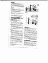
capable of precisely controlling temperatures from 64-135°F (18-55°C) and humidity from 5-
98% RH. (NOTE: The entire humidity range cannot be obtained at all temperatures due
primarily to dew point considerations as shown in Figure 1.0-1.)
32
40
50
60
70
80
90
100
110
120
130
0
10
20
30
40
50
60
70
80
90
100
Relative Humidity (%)
Temperature (Farenheit)
(Lowest RH) (Highest RH)
Figure 1.0-1: Model 5532 Dew point performance chart
The overall dimensions of the Model 5532 are 54”Wx25.5”Dx22”H (137x65x56cm). The usable
interior working space measures 39”Wx20”Dx21”H (99x51x54cm).
1.1 Chambers Controllers & Operating Systems
The controllers, pumps and the humidifier operating system are housed in a separate
compartment on the right side of the Chamber as shown in Figure 1.0-2.

2
Figure 1.0-2: Model 5532 Controlled Environment Chamber
The systems are totally accessible via the removable white, acrylic panel on the right
side of the Chamber. Controllers and operating systems that are available with the
Model 5532 are as follows:
1. Microprocessor Temperature Controller (multi ramp/soak, set point display;
Std.)
2. Model 554 Temperature compensated RH and RTD Temperature Sensor
(Std.)
3. Integrated 500 Watt Heater (Std.)
4. Choice of Cooling Systems: (5473-150W - Std.)
a. Model 5473-(150W-400W) 510-1360 BTU Thermoelectric Cooling System
b. Model 5463 Liquid CO
2
Cooling System
c. Model 5566 Liquid Nitrogen Cooling System
d. Model 5475 Variable Load Refrigerated Cooling System
5. Microprocessor Humidity Controller (multi ramp/soak, set point display, Std)
6. Model 5472 Ultrasonic Humidification System (Std)
7. Choice of Dehumidification Systems:
a. Model 5471 Desiccant/Pump Dehumidification System - 2.5 lbs. of
Desiccant (Std.)
b. Model 5478 Self-Regenerating Dehumidification System (requires external
air compressor or house air at 50-100 psi)
c. Model 5465 Dry Gas Dehumidification System

3
8. CALCOMMS Computer Software/Interface Package. Allows remote
monitoring, charting and reprogramming of the Microprocessor Controllers
from a PC (Std).
1.1.1 Front Panel Description
The front panel of the Model 5532 Chamber is shown in Figure 1.0-3.
Figure 1.0-3: Model 5532 Chamber Front Panel
1.1.1.1 Microprocessor Controllers
The Model 5532 utilizes CAL 9500P microprocessor control modules to
control the humidity and temperature in the chamber. The controllers may
be operated as stand-alone units or as part of a computer-controlled
system using the included CALCOMMS software package that can
control, monitor and log up to 32 control modules 16 Chambers)
simultaneously.
The 9500P module displays both the measured parameter and set point
simultaneously, performs multiple ramp/soak cycles and includes a third
set point for alarming. Point source LED’s in both modules display the
operating status of the control function. Front panel ON/OFF switches
enable the respective operating systems to be placed in standby without
disturbing controller settings.
Controllers can be programmed as either ON/OFF, or as proportional
control where the process is constantly monitored and power to the
operating system pulsed at a rate that maintains the parameter measured
at the sensor, to within ±0.2 of the set point.

4
Refer to Sections 3.0 and 5.0 respectively for a full explanation of all
functions and features.
1.1.1.2 Front Panel Switches
1. ‘POWER’ - The Main Power Switch is the black rocker switch located
directly below the Temperature Controller, to the left of the Fan Power
Knob. This switch disconnects all power going to the Chamber
Systems. “I” is “ON”, “O” is “OFF”.
2. ‘FAN’ - The Variable Fan Speed Control Knob is located to the right of
the Power Switch. This switch controls the speed of the circulation fans
inside the cabinet workspace.
3. ‘TEMP’ – Allows the user to manually disable the Temperature Control
System. Pushing this switch to the “Off” (‘0’) position manually
disconnects the low voltage control signal from either of the
Temperature Control Relays independently. The Microprocessor will
still show the Temperature in the display, the set point may still be
adjusted, the internal LEDs will still illuminate and the AC Power will
still be sent to the solid state Control Relays. The Relay “Output” will
‘open’ because the low voltage control signal will no longer be
connected to the Relay, therefore, the corresponding Temperature
system will not receive AC Power and will not operate.
4. ‘RH’ – Allows the user to manually disable the Humidity Control
System. Pushing this switch to the “Off” (‘0’) position manually
disconnects the low voltage control signal from either of the Humidity
Control Relays, independently. The Microprocessor will still show the
Relative Humidity in the display, the set point may still be adjusted, the
internal LEDs will still illuminate and the AC Power will still be sent to
the solid state Control Relays. The Relay “Output” will ‘open’ because
the low voltage control signal will no longer be connected to the Relay,
therefore, the Humidity systems will not receive AC Power and will not
operate.
5. ‘LIGHT’ - The Light Switch is located to the right of the POWER
Switches, left of the FAN Speed Knob. This switch controls the
overhead light installed in the Chamber workspace.
1.1.1.3 Sensors & PC Boards
The Sensor Input and Control Relays are contained on a PC Board,
located at the rear of the Front Panel.
1. Switches - The switches are mounted to the front panel, (refer to
Figure 1.0-3).

5
2. Relays - The solid-state relays are removable and mounted in sockets
secured with plastic cable ties on the PC Board.
3. Sensor Input - The Sensor Input is the 5-pin DIN jack located in the
lower right corner of the PC Board. The ETS Model 554 RH Sensor
consists of a Temperature Compensated Relative Humidity Sensor
and a RTD Temperature Sensor and is plugged into this jack. The
Sensor Head (Sensing Elements) must be in the 5532 Chamber
environment. The sensor is held in place on the divider wall with a ¾”
NPT plastic compression fitting.
The input is configured at the factory to accept the signal from the ETS
Model 554 Humidity/Temperature Sensor. The Model 554 signals are
both 0-1VDC, corresponding 0-100% RH and 0-100 °C (32-212°F),
respectively.
1.1.2 Side Interface Panel Description
All user connections to the Chamber are made through the Side Interface
Panel shown in Figure 1.0-4. Power connections, Operating Systems
connections and the Computer interface are all located on this panel. The
Side Interface Panel is a modular layout that is modified to meet the
specifications of the Operating Systems ordered with the Model 5532
Chamber. Tube fittings may be added/removed and power outlets may be
added/removed. The following sections will describe the main features of
the Side Interface Panel in the Standard Model 5532 Configuration. For
other configurations, specific installation instructions will be included.
Figure 1.0-4 Model 5532 Side Interface Panel
1.1.2.1 AC Power (Mains)
Labeled POWER, this Universal IEC power connector is located on
the bottom, left corner of the panel. The Voltage supplied (Mains)
must match the Chamber Voltage. All Chambers are 115 VAC/60
Hz, unless otherwise specified.

6
1.1.2.2 COMM PORT (RS-485 & Analog Voltage Outputs)
The Comm Port is the 9-pin subminiature-D jack (sub-D) located
directly above the AC Power Cord Input. This connector is used for
both the analog sensor output signals and the RS-485
communications output from both the Temperature and Humidity
Microprocessor Controllers. Comms access to either, or both, units
is gained through this jack. (Refer to Section 6.0, CALCOMMS
Computer Interface.)
1. RS 485 Computer Interface
The RS 485 portion of the Comm Port is active with the
standard Controllers fitted with the COMMS option (See Section
1.2.1 LEVL C). The COMMS option allows the microprocessor
to communicate with a PC running the CALCOMMS software.
RS-485 Wiring Connections
Tx/Rx+ = Pin 7
Tx/Rx- = Pin 2
Ground = Pin 4
If using the CALCOMM computer program, refer to Section 6.0
“CALCOMMS-Computer Interface” for set-up instructions.
2. Analog Voltage Output
The Analog Voltage Output is always active. Temperatures of 0-
100°C (32-212°F) correspond to an output of 0-1VDC. Relative
Humidity of 0-100% RH also corresponds to an output of 0-
1VDC. The analog output is a direct voltage reading from the
sensors.
This connector is configured as an Analog Voltage (0-1VDC)
Output for monitoring the temperature and/or humidity
performance using a chart recorder or any other analog input
device. The minimum acceptable input impedance for the
analog recording device is 20K ohms. Input impedance lower
than 20K ohms will affect sensor accuracy of the entire system.
Analog Voltage Output Wiring Connections
Temperature Positive (+) Pin 9
RH Positive (+) Pin 1
Common (Gnd) (-) Pin 4

7
1.1.2.3 DEHUMIDIFY IN/OUT
The Model 5471 Desiccant/Pump Dehumidification System uses a
pair of Quick Disconnect fittings. The Pump is inside the Chamber
Control Cavity and the Desiccant Column is outside the Chamber.
These two fittings (AIR IN & AIR OUT) connect the Column into the
Dehumidify loop. (Refer to Section 2.2.1 Dehumidification
System)
1.1.3 Operating Systems Compartment
The Operating Systems compartment, shown in Figures 1.0-5a, b & c,
contains the control electronics, humidifier and dehumidifier pumps,
ultrasonic humidifier, control electronics, fluorescent light ballast plus
access to the sensor.
Figure 1.0-5a: Operating Systems compartment

8
Figure 1.0-5b: Inside left side Figure 1.0-5c: Inside right side
1.2 Controlled Environment Description
The controlled environment section of the Chamber is 13 ft
3
. (0.32 m
3
) with a useable
internal working space of 39”Wx20”Dx21”H (99x51x54 cm). Located on the rear wall is
an aluminum panel that protrudes 4” inside and contains the heater, thermal safety
switch, variable speed 110 cfm fans that are controlled by a speed control knob located
on the front panel. Also included is an accessory north American GFI power outlet.
Mounted to the top of the unit is a weather-tight 18-Watt fluorescent light (controlled by
an ON/OFF switch located on the front panel.
The standard thermoelectric cooling system is mounted to the rear wall behind the
aluminum panel when the chamber is equipped with either of those cooling systems.
The wall separating the controlled environment from the electronics compartment is
0.25” acrylic and contains the humidity and temperature sensor, dry air in/out ports plus
the gas cooling fitting, if so equipped. The humidifier output is located on the upper
middle portion of the wall.
The left hand side of the Chamber consists of a 12"W x 4"H (30.5x10cm) opening with a
hinged access door secured by three (3) ½-turn latches. Towards the rear is a 1.25"
(32mm) ID access hole for feeding cables and tubing to instrumentation placed inside.
This hole should be sealed using the soft putty compound provided.
Humidifier
Sensor
Sensor
Cable
Sensor
Cable

9
The front of the Chamber consists of a large door containing a pair of 8” (20cm) dia.
ports to accept gloves or optional iris ports. The standard Model 5532 is equipped with
accordion sleeves with removable #10 size latex rubber gloves (other sizes and types of
gloves are available). Silicon rubber iris ports or a solid door are also available as
options. The access opening is 32"W x 14"H (81x36cm) which enables large objects to
be placed inside. To the right of the front door is the humidity and temperature control
module. This module is easily removed for servicing by loosening the four (4) captive
mounting screws.
1.3 General Specifications
Section B:
1.4 Unpacking Chamber
The standard Model 5532 Controlled Environment Chamber is shipped in 2 separate
cartons. The chamber is double boxed in double-wall custom cartons and the
accessories, shown in Figure 1.0-6, are packed in a second double-walled carton.
Chamber:
Material: Fans: 2x110 cfm (6230 l/min), ON/VARY/OFF
3/8” (6mm) clear & white acrylic Access Ports: (right side)
Construction: 2x¼” (6mm) Quick disconnects
PS30 polished welded seams 1x1” (25.4mm) Hose barb
Doors:
3/8” (9mm) clear acrylic, ½-turn latches 1x1½” (31.4mm) cable pass through
Seal: (located on left side)
¼” (6mm) Poron, non-setting gasket Lighting: 18W sealed fluorescent, ON/OFF Sw
Gloves: (when configured) Dimensions:
.018” (0.5mm) replaceable hands, natural rubber, Overall: 54”Wx29”Dx22”H (137x65x56cm)
accordion sleeves, 8” (20.3cm) ports Working space (useable): 39”Wx20”Dx21”H
Operating Range: (99x51x54 cm)
Humidity: <10 to >98% Weight: 120 lbs (55 kg)
Temp: (Std) 64-135°F (18-55°C
Controllers: Operating Systems:
Type: 2x CAL 9500, multiple ramp/soak cycles Dehumidify: Desiccant/Pump
1x CAL 9500, (opt.) 3
rd
parameter, linear input 2.5 lb (1.1kg) CaSO
4
/1.2cfm
Resolution: 0.1%/0.1° Humidify: Ultrasonic
Set Pt. Tracking: ±0.1 Capacity: Tap water or 5 gal (19 l) ext. tank
Rec. Out: 0-1vdc, 0-20ma, 4-20ma Flow rate – 0.06 cfm (max)
Computer IF: MODBUS proto. Via RS485- Heat: Electric, 500W
PC with W98 or higher, NT Cool: 150W Thermoelectric (Std), 300W (Opt)
Sensor: Power:
Type: Temp compensated RH/Temp Voltage: 115/230VAC, 50/60Hz
RH: Capacitive film, 0 to 100%, non-condense Current: 8-10 Amps
Temp: RTD, -40 to +140°F (-40 to 60°C)
Accuracy: ±1.5% RH @ 72°F (22°C)
±0.5°F (±0.3°C)

10
Deionizer Column 5 lb Desiccant
5 Gal Water
Tank
2.5 lb Desiccator
Column
¼” Polyflo tubing
Spare Gloves
3 Stackable
Racks ¼” Quick
Disconnect
RS485/232 CALCOMMS
Converter Software Disc
Figure 1.0-6 Accessory box contents
Upon receipt immediately inspect the cartons for any visible damage. If any shipping
damage is noticed, unpack the chamber and inspect it for damage. Take pictures of any
abnormalities observed. Save all cartons until it is certain that they will no longer be
needed. If the Chamber has to be returned to ETS for any reason the original packaging
must be used.
NOTE:
Report any damage immediately to the common carrier delivering the System and
to ETS. All damage claims must originate from the recipient.
Failure to report
damage in a timely manner may result in the claim not being paid. ETS will not be
responsible for damaged or lost components if not reported to ETS within 30
days of shipment.
Save all cartons and packing material until the Model 5532 System is installed
and operating.

11
2.0 HUMIDITY OPERATING SYSTEMS
2.1 Humidification System
The Model 5532 Chamber includes an ETS Model 5472 Ultrasonic Humidification
System. The Humidifier is located inside the Chamber Control Cavity as shown in
Figure 1.0-5c. To access the Humidifier, remove the large white acrylic panel on the
right hand side of the Chamber as shown in Figure 1.0-5a. The panel is held in place
with eight (8) Phillips, #6-32 Truss Head screws.
Refer to the Set-up instructions below before using the Humidifier!!
The Ultrasonic Humidifier is an open loop system that produces a fine water mist
through ultrasonic action. A small diaphragm air pump draws in ambient air and forces
the fine mist from the humidifier into the chamber.
2.1.1 Ultrasonic Humidifier Accessories
The following are the humidification system accessories (Refer to Figure 1.0-6).
1. 5 Gallon Water Tank
a. Tank includes a plastic faucet. When shipped, the faucet is
attached to the white lid, protruding inside the tank.
b. A ¼” OD Tubing Quick Connect Fitting is attached to the Faucet.
2. Water Deionizer Column
a. #10 Clear Sump with black Lid and ¼” OD Tubing Connectors.
b. The Column is filled with a mixed bed deionizing resin for water.
c. The Column has Filter Pads on the input and output. The Filter
Pads are held firmly in place by a cadmium plated steel spring.
2.1.2 Set-Up
The Model 5532 comes with green Caplugs covering the “mist output’ and the
‘chamber vent’. These Caplugs must be removed before set-up and operation.
The Model 5472 Humidifier may be operated using either a water tank or directly,
without a tank, from a faucet using the included de-ionizer column. Use distilled
or de-ionized water ONLY!!
A water de-ionizing column is included, suitable for up to 100 psig. (NOTE: The
life of the de-ionizing column will be greatly increased by using a carbon black
water filter, provided by the user, in line with the deionizer.)
When the de-ionizing resin is depleted, it will change from dark to light in color.
When it is ¾ light, it must be replaced. Resin is available from specialty chemical

12
suppliers such as Resintech Inc., Pt# MBD-30. They can be reached at 1-865-
768-9600. They are located at 160 Cooper Rd., Berlin, NJ 08091
2.1.2.1 Using the Water Tank
When using the water tank distilled or de-ionized water can be obtained
from either a separate source or de-ionized water can be generated by the
supplied de-ionizer column. Place the tank on the floor or other surface
with the openings facing up.
1. If the de-ionizer is being used to supply the water, attach the
water de-ionizing column to a water supply. The supply water
should go to the side marked “IN”. The de-ionizer is fitted with a
¼” tube connected to a ¼” NPT quick disconnect fitting. The
user must provide the appropriate fitting to adapt the de-
ionizer ¼” NPT fitting to the supply water line.
2. Unscrew the large white cap from the tank and remove the
plastic faucet. Install the faucet onto the smaller tank fitting.
Turn the faucet lever to closed (LEFT), the 9:00 o’clock position.
With the faucet outlet facing downward screw the large cap onto
the larger fill hole. Place the de-ionizer outlet tube into the
smaller opening in the large white cap.
3. Turn on the water.
The water flow rate through the purifier should not exceed 8oz.
every 25-30 seconds. Water will pass at up to 10 gallons per
hour.
NOTE:
Do not increase the flow rate! The amount of water purification
is in direct proportion to how long it takes the water to flow
through the column.
Slow flow rate = highly purified water.
Fast flow rate = poorly purified water.
4. Fill the tank with the amount of water that can be used in 1-2
weeks of normal operation at the required operating conditions.
Different operating conditions will consume different amounts of
water. Leaving water in the tank longer than 1-2 weeks is not
recommended. Always refresh the water supply to prevent the
growth of bacteria and other things that will degrade water
quality. NEVER add anti-bacterial growth treatment to this
water, it will damage the humidifier.

13
5. Turn off the water source and remove the fill tube. NOTE: The
de-ionizer column should not be used to continuously fill
the tank. There is no mechanism to automatically turn off
the water supply when the tank is full.
6. This is a gravity-feed system that requires the source tank to be
above the humidifier. Also, air must be allowed to enter the 5-
gallon tank or water will not flow. Remove the small white cap, if
it had previously been reinstalled after the filling the tank, to
allow air to enter. Place the water tank output at least 12” above
the humidifier water input. Placing the water tank on top of the
chamber is acceptable.
7. Make sure the faucet is closed, then push the ¼” OD. tubing
into the quick connect fitting.
8. Attach the other end of the tubing to the fitting on the Chamber
side panel labeled ‘WATER IN’. Turn on the tank faucet (full
right @ 3:00 o’clock position)
9. Turn on the ‘RH INCREASE’ switch.
The Humidifier basin will begin to fill with water as soon as this
switch is turned ‘ON’.
2.1.2.2 Using the Tap Water System
1. Attach the water de-ionizing column to a faucet. The faucet
should go to the fitting on the column lid labeled “IN”. The de-
ionizer is fitted with a ¼” tube connected to a ¼” NPT quick
disconnect fitting. The user must provide the appropriate
fitting to adapt the de-ionizer ¼” NPT fitting to the supply
water line.
2 Turn on the water. Establish the proper water flow rate before
attaching to the humidifier. The water flow rate through the
purifier should not exceed 8 oz. every 25-30 seconds. Water will
pass at up to 10 gallons per hour.
NOTE:
Do not increase the flow rate! The amount of purification that
can be performed on the water is in direct proportion to how
long it takes the water to flow through the column.
Slow flow rate = highly purified water.
Fast flow rate = poorly purified water.
Attach the open end of the tubing to the ‘WATER IN’ fitting on the
side of the ETS Model 5532 Chamber.

14
3. Turn on the water. Set the flow rate to the pre-determined
amount. DO NOT OPERATE THE HUMIDIFIER WITH THE
WATER SUPPLY FAUCET 100% OPEN. High flow rates will
cause the humidifier to overfill and possibly damage the unit.
The humidifier consumes very little water; a low flow rate will be
sufficient to keep the unit full.
4. Turn on the ‘RH INCREASE’ switch. The Humidifier basin will
begin to fill with water as soon as this switch is turned ‘ON’.
2.1.3 Operation
Once the System has been properly set up, the user does not have to do
anything else to operate the system. Operation will be under the control of the
Model 5532 Microprocessor Humidity Controller. Refer to Section 3.2
Microprocessor Humidity Controller Operation.
1. Remove the green Caplug covering the Chamber Vent.
The vent, inside the chamber, is the 1” (25mm) orifice on the right wall
(the green plug is located here). The vent passes through to the outside
right wall. The 1” (25mm) barb on the outside should remain open.
2. Set the Humidity Controller set point to a value above ambient humidity
(Refer to Section 3.2.1 Microprocessor Humidity Controller
Operation).
3. Turn on the “RH INCREASE” switch on the Model 5532 front control
panel.
This will not automatically turn on the Humidifier. Turning on the “RH
INCREASE” switch only makes the humidifier available to the
Microprocessor Controller.
When the microprocessor tells the Humidifier to activate, the small
green LED in the upper, left corner of the microprocessor will light. The
Humidifier will begin producing a mist and the pump will force it into the
chamber through the Humidity Input Barb.
4. The microprocessor will determine the amount of humidification
needed to maintain the desired set point.
If less than the full capacity of the Humidifier is needed, the controller
will provide pulses of power to the unit to limit the output. The
Humidifier will be turned on and off cyclically to obtain an average
humidity output lower than the full capacity of the Humidifier.

15
NOTE:
To obtain a smooth, even humidity output the Cycle Time (CYC.t) should
be set to 1.0 second. Longer cycle times will create longer “gaps”
between humidification pulses. DO NOT SET THE CYCLE TIME LESS
THAN 1.0 SECOND. Shorter pulses may damage the Model 5472.
2.1.3.1 Operating Precautions
The humidifier should operate reliably if the following precautions
are observed:
1. Always run the humidifier directly to the chamber.
Never attempt to combine the humidifier output with another air or
gas source.
2. Always provide a vent on the chamber being humidified.
3. Clean the ultrasonic transducer frequently and thoroughly.
Any dirt or particle build-up on the transducer will cause stress to
the electronics. Once the electronics overheat and stop working,
the humidifier must be replaced. With frequent cleaning, the
electronics should operate reliably for many years.
4. Use Distilled or Deionized water only.
2.1.3.2 Maintenance & Cleaning
1. Always unplug the Chamber before cleaning the humidifier.
2. Empty the unit of all water. Siphon water out or soak up with a
sponge.
3. Remove the humidifier top cover by removing the 4 brass
thumbscrews
4. Clean the surface of the transducer using distilled vinegar
and a soft, clean cloth.
NOTE:
If the transducer is not kept clean, it will fail. Using distilled
or deionized water keeps the build-up to a minimum, but
cleaning with distilled vinegar will always be necessary.
Do not use any tools with metal parts or sharp edges to
clean the transducer. Scratching the transducer may cause
fatal damage to the unit. Refer to Section 8.0
MAINTENANCE for transducer replacement.

16
5. To clean thick or heavy deposits, pour a small amount of
vinegar into the humidifier until the transducer surface is
completely covered. Let stand for 30-60 minutes. Wipe clean
with a soft cloth. If further cleaning is needed, a soft, plastic
bristle brush may be used to gently clean the transducer
surface.
6. Never leave water in the humidifier or water tank when the
humidifier is not in service.
Always empty all water and thoroughly dry all parts of the
humidifier when it is to be stored or taken out of service for any
period longer than one week. Do not seal the water tank in
storage. Leave the top off to allow the air to completely dry the
tank. Any residual moisture will encourage bacterial growth.
Never clean any parts of the humidifier with water above 120°F.
2.2 Dehumidification System
The Model 5532 Chamber includes a Desiccant-Pump Dehumidification System
as standard. As an option, the ETS Model 5478 Self-Regenerating
Dehumidification System is available. Operation of each system will be described
below.
2.2.1 Desiccant/Pump Dehumidification System
The Dehumidification System is closed loop designed to reduce the
relative humidity in the Model 5532 Chamber to less than 10%. When
paired with the Microprocessor Humidity Controller, the humidity inside the
chamber can be controlled, without disturbance, to within +/- 0.2% RH of
the set point at the sensor.
2.2.1.1 Description
The Dehumidification System includes a small air pump (located
inside the Chamber Control Cavity), 2.5 lbs. of indicating calcium
sulfate (CaSO
4
) desiccant in a clear plastic column (sits outside the
chamber), and ¼” O.D. tubing to interface the drying column with
the pump. The tubing connects to the chamber through the quick-
connect fittings on the right side of the Chamber. The desiccant
column may be placed on top of, or next to, the Chamber.
The air pump is already connected to the Model 5532
Microprocessor Humidity Controller. All the user needs to do is
connect the Desiccant Column into the system using the provided
¼” OD Tubing.

17
The desiccant removes any moisture that is in the air. This dried air
is then forced back into the chamber. The desiccant contains an
indicator that turns the normally blue colored desiccant pink as it
absorbs moisture. When the cylinder is mostly pink, the desiccant
should be renewed or replaced.
2.2.1.2 Desiccator Unit Specifications
1. Average flow-rate from the unit is 1.2 cfm (34 lpm).
2. Air is dried to a dew point of -100°F.
3. Capacity for water vapor up to 100 grams.
4. Power – 115 VAC/60 Hz, 0.35
230 VAC/50 Hz, 0.18 Amps
5. Desiccant Column is safe for working pressures up to 100 psig.
6. Contents: 2½ lbs. of #8 mesh CaSO
4
Indicating Desiccant.
7. All connections are made using ¼” OD tubing. Hose barb adapters
may be provided for using ¼” ID tubing as an alternative.
8. Plastic cap is fitted with “O-Ring” gasket.
9. Desiccant coil spring is cadmium-plated steel.
The system delivers air dried to a dew point of -100°F. At room
temperature, the system will lower the humidity in the Model 5532
Chamber from 50% RH to 12% RH in about 2 hours.
2.2.1.3 Desiccant Dehumidification System Set-Up
1. Place the desiccant column somewhere near the chamber. (Next to or
on top of the chamber are good locations.)
2. Cut 2 pieces of the ¼” OD tubing long enough to connect the desiccant
column to the ‘Side Interface Panel’ of the Chamber.
3. Connect one piece of the tubing between the fitting labeled
“DEHUMIDIFY OUT”, on the Side Interface Panel of the Chamber, and
the fitting labeled “IN” on the desiccant column.
To connect the tubing: Push the tube into the fitting orifice as far as
possible. The tube will lock into place automatically. To release the
tube, push in on the collar of the fitting and gently pull out the tube.
4. Connect the second piece of tubing between the fitting labeled “OUT”
on the desiccant column and the fitting labeled “DEHUMIDIFY IN” on
the Side Interface Panel of the Chamber.
/