Page is loading ...

GBE 06/23
365
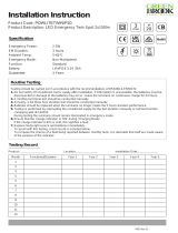
Installation Instruction
Product Code: GBGMHOSTEMWH
Product Description: LED Emergency Bulkhead
Specification
Testing Record
1
2
3
4
5
6
7
8
9
10
11
12
Functional/DurationMonth Year 1 Year 2 Year 3 Year 4 Year 5
Product: _______________ Location:_____________ Installation Date:____________
Charge Power:
Discharge Power:
EM Duration:
Ambient Temp:
Emergency Mode:
Function:
Battery:
Warranty:
4.5W
10W
3 hours
5-45°C
Non-Maintained
Self Test
LiFePO4 6.4V 6.6Ah
3 years
Routine Testing
Testing should be carried out in accordance with the recommendations of BS5266 & EN50172.
1. Do not switch off unswitched mains supply after installation. If interruption is unavoidable, the batteries must be
disconnected or damage to the batteries may occur. Leave the luminaire on continuous charge for 24 hours.
2. Batteries should be replaced when the luminaire no longer meets the 3 hours duration performance.
3. Testing is performed by interrupting the unswitched supply for the test duration manually or self-test function
complying with IEC62034.
During testing the luminaire should remain illuminated in emergency mode.
4. Ensure that the ‘charge indicator’ is ‘ON’ during ‘Charging Mode’.
If the charge indicator (LED) is unlit, this signifies a fault.
5. Replace faulty light source and batteries immediately.
To assist with this testing, a test record is included below.
To increase the chance of a fault being reported between monthly tests, it is desirable that staff are made aware
of the purpose of the indicator.
GBGMHOSTEMWH Ins Jun 23_Layout 1 16/06/2023 14:52 Page 1

GBE 06/23
Installation Instruction
12 3
4
Dimension
321mm
167mm
83mm
ALWAYS SWITCH OFF THE
MAINS SUPPLY BEFORE
INSTALLATION OR SERVICING
Ceiling
Drill hole in base tray
N
L
Model B
Ceiling
N
L
Drill hole in base tray
Model A
x4
GBGMHOSTEMWH Ins Jun 23_Layout 1 16/06/2023 14:52 Page 2

GBE 06/23
Installation Instruction
5
6 7
8
10
9
Connect battery
to converter Connect power
supply to LED board
Jumper Switch-L-1000lm
Jumper Switch-H-1500lm
x4
GBGMHOSTEMWH Ins Jun 23_Layout 1 16/06/2023 14:52 Page 3

GBE 06/23
GBGMHOSTEMWH Ins Jun 23_Layout 1 16/06/2023 14:52 Page 4

GBE 06/23
GBGMHOSTEMWH Ins Jun 23_Layout 1 16/06/2023 14:52 Page 5
/


