Page is loading ...

Texmate, Inc. Tel. (760) 598-9899 • www.texmate.comUM-35-CL manual (UM04) Page 1
General Features
Specifications
Typical Application Connections
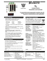
4 to 20mA Process Loop Measurement
24V
External
Loop Supply
Common
Oset
0
+
_
Other devices can be
added to the loop.
< Decrease Zero Increase >
< Decrease Span Increase >
Range
HI
LO
OFF
ON
24V EXC
Fully User Scalable
PIN 2
+_
Input Configuration: ........Series connection to 4-20mA process loop.
Full Scale Ranges: ..........User adjustable to any scaling between
-1999 to +1999.
Input Impedance: ............. 70Ω. Maximum 1.4V drop
A/D Converter: .................12 Bit Dual Slope
Accuracy: .........................±(0.05% of reading + 2 counts)
Temperature Coefficient: 100 ppm/°C (Typical)
Warm Up Time: ................2 minutes to specified accuracy
Conversion Rate: ............. 3 conversions per second (Typical)
Display:.............................3 1/2 digit 0.56" Red LED display (std),
Green or Super Bright Red are optional.
Range -1999 to 1999 counts.
Polarity: ............................Bipolar. Assumed positive displays negative.
Decimal Selection: ..........Header under face plate, X•X•X•X•
Over-range Indication: ....1 (MSD) displayed all other digits blank
Power Supply (PS6 std): �
Auto-sensing
85-305VAC or 120-430VDC,
50/60Hz App. 1W
(PS7 opt.) .
Isolated (1.5kV) auto-sensing 9-36 VDC 1W
(PS11 opt.) ..
Isolated (1.5kV) auto-sensing 36-75 VDC 1W
(PS8 opt.) .5VDC/200mA
Operating Temperature: .. –10 to 50 °C
Storage Temperature: .....–20 to 70 °C.
Relative Humidity: ...........95% (non-condensing)
Case Dimensions: ...........Bezel 3.78”Wx1.89”H (96mm x 48mm)
Depth behind bezel 3.36" (83.5mm) Plus
0.5 to .9” (12.7 to 22.8mm) depending on
connector used.
Weight: .............................NW. 12oz (0.34kg)
15.6oz (0.44kg). when packed.
UM-35-CL
4-20mA Process Loop
Reliable Process Loop indicator with
scalable capabilities from -1999 to +1999
to represent any engineering units, FLOW,
LEVEL, TEMPERATURE, PRESSURE.....
The UM-35-CL is an cost-effective 4-20mA process loop mea-
suring meter. It is easily user adjustable to any reading between
-1999 and +1999 with header selectable signal conditioning.
UM-Series
Optional super
bright LEDs
UM-Series utility meters for switchboard and process indication
3 1/2 DIGIT with 0�56” LEDs
in a NEMA type 1 Style Case
UM-35-ACA
....AC amps, True RMS, (1 or 5 Amp internal shunt), 3.5 digit.
UM-35-ACV
......AC volts, True RMS. 199.9V AC/700V AC header selectable ranges, 3.5 digit.
UM-35-DCA
....DC mV ±20mV/±50mV/ ±100mV/±200mV header selectable ranges, 3.5 digit
UM-35-DCV
.....DC Volts ±2V/±20V/±200V DC header selectable ranges, 3.5 digit.
UM-40-ACV
....AC volts, True RMS. 199.9V AC/700V AC header selectable ranges,4.0 digit.
UM-45-DCA
.....DC mV ±20mV/±50mV/ ±100mV/±200mV header selectable ranges, 4.5 digit
UM-45-DCV
....DC Volts ±2V/±20V/±200V DC Header selectable ranges, 4.5 digit.
UM-35-CL
.......Process 4 to 20mA (100.0), easily user scalable in engineering units from
–1999 to +1999. 3.5 digit
UM-35-HZ
.......15Hz to 199.9Hz or optional 40Hz to 400Hz up to 500V AC , 3.5 digit.
UM-35-SG
.......Pressure, strain gage and load cell, 4 and 6 wire, 5V DC excitation,
Header Selectable Sensitivity 2mV/V, 5mV/V, 10mV/V, 20mV/V, 3.5 digit
UM-35-JF
........ J thermocouple input, 1° resolution, order °C or °F, 3.5 digit
UM-35-KF
.......K thermocouple input, 1° resolution, order °C or °F, 3.5 digit
UM-35-RTD
.....100Ω platinum RTD, 3 or 4 wire, order °C or °F and 0.1° or 1°, 3.5 digit
UM-45-CL
.......Process 4 to 20mA (100.0), easily user scalable in engineering units from
–19999 to +19999. 4.5 digit

Texmate, Inc. Tel. (760) 598-9899 • www.texmate.comPage 2 UM-35-CL manual (UM04)
Component Layout
Calibration Procedure
Decimal Point Selection
1.XXX
1X.XX
1XX.X
1XXX
Cut loop to turn
OFF last digit
0.56" Display
Decimal Select
Header
Connector Pinouts
This meter uses plug-in type screw terminal connectors for all
input and output connections. The power supply connections
(pins 14 and 15) have a unique plug and socket outline to
prevent cross connection. The main board uses standard right-
angled connectors.
14 15
10 11
12 3 12
AC/DC Power
ZERO
SPAN
HOLD
TEST
COMMON
AC
Neutral
– DC
AC
Line
+ DC
Signal Input Pin
This meter uses plug-in type
screw terminal connectors for
all connections.
Connectors
!
WARNING: AC and DC input signals and power supply voltages can be
hazardous. Do Not connect live wires to screw terminal plugs, and do not
insert, remove or handle screw terminal plugs with live wires connected.
Decimal selection
is made by moving
the jumper to the
indicated position
on the header for
the decimal required
on the front of the
display board.
To open meter, insert
a flat head screwdriver
or similar instrument in
both slots on the side
of the cover and pry
open. The UM-Series
meters slide out from
the front of the case as
a complete assembly.
The first step is to disengage the ZERO Pot and scale down the
Signal Span input to produce the desired Digital Display Span
output.
Signal Span is defined as the total change of signal input that
would be required for a specific change of the Digital Display.
The largest Signal Span that can be specified with a 4 to 20mA
input is 16mA. A 4mA Signal Span proportionately scaled can
meet full scale display accuracy.
Digital Display Span is defined as the exact total in counts,
that the display would change within a specific Signal Span.
The largest Digital Display Span that can be displayed is -1999
to +1999 (4000 counts). 16mA can not display +4000, so
instead 4mA can be scaled to +1000.
The second step is to select a Zero Offset Range and offset the
Digital Display Span with the ZERO Pot, until the desired reading
is displayed.
Maximum offset is -3000 to +2000 counts. A Digital Display
Span of 4000 counts requires an offset of -3000 to display
-1999 to +1999.
For example: A 4 to 20mA input to read -40.0°C to +199.9°C
Signal Span = 16mA, Digital Display Span = 2400 counts.
1. Remove the meter from its case and set the Zero Offset
Range Header to the Calibrate position. Select the 1400 –
3000 position on the Span Adjust Header and slide the meter
back into the case.
2. Connect power to the meter and apply 4mA (25% of 16mA).
Adjust the SPAN Pot until the display reads +600 (25% of
2400). The meter is now scaled for a Signal Span of 16mA
and a Digital Display Span of 2400 counts. In the example
4mA should read -400 and 20mA read 1999, therefore the
Digital Display Span should be offset by -1000.
3. Disconnect power and remove the meter from the case,
select the Negative offset position on the ZERO OFFSET
RANGE Header, and slide the meter back into the case.
4. Connect power to the meter, apply 4mA and adjust the ZERO
Pot until the display reads -400. With the Digital Display Span
now offset by -1000 counts, the meter will read -400 for a
4mA input, and read +1999 for a 20mA input. Select decimal
point 1XX•X to display -40.0 to +199.9. Then apply the self
adhesive °C symbol (from the Face Plate Descriptor sheet
may be ordered. P.N:DU-CASEDES) to complete the calibra-
tion.
SPAN Pot
HI/LOW
SPAN RANGE Header
ZERO Pot
ZERO ADJUST Header
SPAN ADJUST Header
ZERO OFFSET RANGE
Header
Optional Isolated Auto-sensing
9 to 36VDC (P.N.: PS7)
36 to 75VDC (P.N.: PS11)

Texmate, Inc. Tel. (760) 598-9899 • www.texmate.comUM-35-CL manual (UM04) Page 3
SPAN Potentiometer (Pot)
The 15 turn SPAN pot is always on the
right side (as viewed from the front of the
meter). Typical adjustment is 100% of the
input signal range.
ZERO Potentiometer (Pot)
The Optional ZERO pot when installed
is always to the left of the SPAN pot
(as viewed from the front of the meter).
Typically it enables the displayed reading
to be offset ±100 counts.
Optional Face Plate Descriptors
To customize the face plate,
clear adhesive label containing
various popular descriptors may
be ordered. Choose the descrip-
tor desired, peel off the adhesive
backing and align the descriptor
in the center right of the face-
plate.
P.N.: 75-DESCRIPTR
LO RANGE HI RANGE
10%SPAN Pot %10% 10% 10% 10%
10%Signal Span %20% 30% 40% 50%
1
SPAN Adjust
Header position
Span Adjust Header Span Adjust Header
Span Range Header
2 3 4 5
10% 10% 10% 10% 10%
60% 70% 80% 90% 100%
1 2 3 4 5
< Decrease Span Increase >
12 345
< Decrease Span Increase >
12 345
Equivalent
Circuit
Acts like a
150 Tu rn
Potentiometer Low Range High Range
Input LO Input HI
HI
LO
SPAN RANGE Header
When this header is provided it works in
conjunction with the SPAN ADJUST Header by
splitting its adjustment range into a Hi and a
Lo range. This has the effect of dividing the
adjustment range of the SPAN pot into ten equal
10% steps across 100% of the input Signal Span.
Range
HI
LO
HI
LO
< Increase Span Decrease >
54 321
< Increase Span Decrease >
5 4 3 2 1
20%SPAN Pot %20% 20% 20% 20%
20%Signal Span %40% 60% 80% 100%
1
SPAN Adjust
Header position 2 3 4 5
< Decrease Span Increase >
12 345
Acts like 75 Tu rn 1 Mega ohm Potentiometer
Input LO
Input
HI
Equivalent
Circuit
SPAN ADJUST Header
This unique five-position header expands the
adjustment range of the SPAN pot into five
equal 20% steps, across 100% of the input
Signal Span. Any input Signal Span can
then be precisely scaled down to provide any
required Digital Display span from 1999 counts
to 001 (one count).
ZERO ADJUST Header
When this header is provided, it works in
conjunction with the ZERO OFFSET RANGE
Header, and expands the ZERO pot’s offset
capability into five equal negative steps or five
equal positive steps. This enables virtually any
degree of input signal offset required to display
any desired engineering unit of measure.
< Increase Zero Decrease >
54 321
< Increase Zero Decrease >
5 4 32 1
Zero Offset Range Header
0+–
–20%ZERO Pot %–20% –20% –20% –20%
No
Offset
NEGATIVE OFFSET POSITIVE OFFSET
–1200 or more countsOffset Range
+20% +20% +20% +20% +20%
+1200 or more counts
5
ZERO Adjust
Header position 4 3 2 1 1 2 3 4 5
75 Tu rn Potentiometer
–0
Equivalent
Circuit
< Increase Zero Decrease >
54 321
< Decrease Zero Increase >
12 345
75 Tu rn Potentiometer
+0
Zero Pot
Disabled
ZERO OFFSET RANGE Header
When provided, this three position header
increases the ZERO pot’s capability to offset the
input signal, to ±25% of the digital display span.
For example a Negative offset enables a 1 to 5V
input to display 0 to full scale. The user can select
negative offset, positive offset, or no offset (ZERO
pot disabled for two step non-interactive span and
offset calibration).
Offset
0
–
+
0
–
+
Zero Offset Range Header
0+–
No
Offset
NEGATIVE OFFSET
Decreases Digital Reading
POSITIVE OFFSET
Increases Digital Reading
15 Tu rn Potentiometer
–0
Equivalent
Circuit
15 Tu rn Potentiometer
+0
Zero Pot
Disabled
⊕ – 500 CountsOffset Range
– 100% of Offset
ZERO Pot%
⊕ + 500 Counts
+ 100% of Offset
Signal Conditioning Compenets

Texmate, Inc. Tel. (760) 598-9899 • www.texmate.comPage 4 UM-35-CL manual (UM04)
UM Case Dimensions and Panel Cutouts Warranty and User's Responsibility
WARRANTY
Texmate warrants that its products are free from defects in material and
workmanship under normal use and service for a period of one year from date
of shipment. Texmate’s obligations under this warranty are limited to replace-
ment or repair, at its option, at its factory, of any of the products which shall,
within the applicable period after shipment, be returned to Texmate’s facility,
transportation charges pre-paid, and which are, after examination, disclosed
to the satisfaction of Texmate to be thus defective. The warranty shall not
apply to any equipment which shall have been repaired or altered, except by
Texmate, or which shall have been subjected to misuse, negligence, or acci-
dent. In no case shall Texmate’s liability exceed the original purchase price.
The aforementioned provisions do not extend the original warranty period of
any product which has been either repaired or replaced by Texmate.
USER’S RESPONSIBILITY
We are pleased to offer suggestions on the use of our various products
either by way of printed matter or through direct contact with our sales/
application engineering staff. However, since we have no control over the
use of our products once they are shipped, NO WARRANTY WHETHER OF
MERCHANTABILITY, FITNESS FOR PURPOSE, OR OTHERWISE is made
beyond the repair, replacement, or refund of purchase price at the sole dis-
cretion of Texmate. Users shall determine the suitability of the product for the
intended application before using, and the users assume all risk and liability
whatsoever in connection therewith, regardless of any of our suggestions
or statements as to application or construction. In no event shall Texmate’s
liability, in law or otherwise, be in excess of the purchase price of the product.
Texmate cannot assume responsibility for any circuitry described. No circuit
patent or software licenses are implied. Texmate reserves the right to change
circuitry, operating software, specifications, and prices without notice at any
time.
Mounting Clip
Panel Cutout 1.64"
(41.6mm)
3.36"
(85.3 mm)
0.31"
(7.8 mm)
3.58"
(91mm)
3.78"
(96 mm)
3.58"
(90.8 mm)
1.89"
(48 mm)
1.55"
(39.3 mm)
2 PCS
FRONT VIEW
REAR VIEW
SIDE VIEW
SIDE VIEW
0.78"
(19.8 mm)
0.55"
(14 mm)
2.8"
(71.2 mm)
UM Series NEMA Case Dimensions and Panel Cutouts
Power
ZERO
SPAN
Signal Input Pin
UM-35-CL Technical Manual Copyright © 2022 Texmate Inc. All rights
reserved. Published by: Texmate Inc. USA. Information in this Technical
Manual is subject to change without notice due to correction or enhance-
ment. The information described in this manual is proprietary to Texmate,
Inc. and may not be copied, reproduced or transmitted, in whole or in part,
in connection with the design, manufacture, or sale of apparatus, device or
private label product without the express written consent of Texmate, Inc.
Custom Face Plates
Texmate Produces Thousands of Custom OEM Face Plates�
Have Texmate Design and produce a Custom Face Plate for your next
project!
• Custom face plates have a non-recurring artwork charge. A serial
number is then assigned to each artwork to facilitate reordering.
Ordering Information
Standard Options for this Model Number
Part Number Description List
BASIC MODEL NUMBER standard display and standard power supply
unless optional versions are ordered.
UM-35-CL
......
DPM,
Process 4 to 20mA (100.0), (IP01)
................
DISPL AY
DR
......................
0.56” Red LEDs
...............................
UM-BRIGHT ........Super bright Red LEDs, 0.56 inch high ................
UM-GREEN ......... Green LEDs, 0.56 inch high ........................
POWER SUPPLY
PS6 (Std.)
.........
85-305VAC or 120-430VDC, 50/60Hz, Approx.1W
...
PS7
.....................
Isolated (1.5kV) 9-36VDC Approx.1W
PS11 ...............Isolated (1.5kV) 36-75VDC Approx.1W
PS8
.....................5 VDC /200mA ........................................................................
Special Options and Accessories
Part Number Description
SPECIAL OPTIONS (Specify Inputs & Req. Reading)
ZR ........................... Input Range Change to another Standard Range .........
ZRS-SMUM..........Non-standard range change and/or Scale change .................
ACCESSORIES
OP-N4X/96X48
. 96x48mm clear lockable front cover NEMA 4X, splash proof
CASE.RPUM
...
Case: Replacement with Accessories
.............
ART-NRC-DEC
. NRC for Artwork & set-up Custom Faceplate and/or Descriptor
ART-FS1
......Produce & Install Custom Faceplate per meter - 1 color no-min
ART-FS2
......Produce & Install Custom Faceplate per meter - 2 color no-min
ART-FS3
............Produce & Install Custom Faceplate per meter - 3 color no-min
75-DESCRIPTR
Clear adhesive descriptors label for face plate
.....
Removable
Key-lock
Safety
Catch
Cover
Base
O-ring
Gasket
NEMA-4X, IP65 Lockable Cover
(Part Number OP-N4X/96X48)
Clear Lockable Water-proof Cover
The clear lockable cover is designed to be dust and waterproof
to NEMA-4X, IP65 standards. The assembly consists of a base
and a cover with a cam hinge and key-lock fastening mecha-
nism. An O-ring, or neoprene gasket forms a seal between the
base and the panel. The cam hinge prevents the cover from
closing when opened until pushed closed. The cover has a
tapered recess that, when closed, forms a seal with a tapered
spigot on the base. A key-lock employs a cam locking device to
force the spigot into the recess, ensuring seal integrity. A safety
catch keeps the cover closed even when the key is removed,
and the keyhole can be used to attach a safety seal clip,
preventing unauthorized
opening.
1934 Kellogg Ave., Carlsbad, CA 92008
Tel: 1-760-598-9899 • 1-800-TEXMATE • Email: orders@texmate.com
/