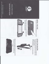
STEP Secure Charger and
Install cable holster
. Secure Charger to Mounting Bracket: Using the kit-supplied tamper-resistant screw– secure the charger cover with one screw
on the side. Use the second screw (underneath the charger) to secure Front Cover to the Charger.
. Install Holster to Charger: Align Holster with guides in charger. Using the kit-supplied tamper-resistant screw, use the third
screw to secure the holster to the charger (hole at the top of the holster).
. Standard installation – using the kit-supplied lag screw, screw into the wall.
. Alternate installation – using the th wallboard screw with anchor, screw into the wall.
DANGER Hazardous voltage. Will cause death or
serious injury. Turn off power before working on this
equipment. This indicates a situation where the present
voltage could cause injury or death. Extreme caution is
required when servicing or installing the equipment
referenced.
NOTE: Any time the interior wiring is exposed while there is power to the unit there is danger of hazardous voltage and serious injury.
STEP Hardwire the
VersiCharge and
Ferrite core
installation (Skip if
using an existing
V outlet)
VersiCharge will need to be mounted on the bracket to hardwire the device.
Plug-supplied units only:
. Open the VersiCharge and expose the wiring.
. Remove barrier by removing the two securing screws.
. Disconnect the attachment plug wires from the terminal block by loosening screws in positions , , and and remove the
Ferrite core (the core will be reinstalled when hardwired).
. Disconnect and remove strain relief and entire cord-and-plug assembly and follow Hardwiring for plug and non-plug units
below.
Hardwiring for plug and non-plug units:
NOTE: Do not adjust the two screws on top of the terminal block unit. These are for factory use only.
. Expose the wiring terminals by opening the back of the unit, unscrew the lugs.
. Route conductors into the VersiCharge from the conductor opening with proper strain relief.
. Pull - inches of slack through the conductor opening.
. Locate the Ferrite core (the Ferrite core supplied in the resealable plastic bag or reserved when the plug was removed). Slide
the Ferrite core over the black and red wires ONLY, and into position per figure (the green wire/ground should not be
placed through the Ferrite core).
. Wire conductors (copper only) into VersiCharge (L, L and Ground) from connected conduit. Using torque screwdriver,
torque all lugs to . lb.-in. See Appendix D for wire bending diagram.
. Replace barrier and secure with the two screws which were removed in the beginning.
. Replace hinged cover, securing with four Phillips head screws.
. Swing the unit closed until the bracket clip engages and secure the charger with the tamper-resistant security screws.
. Turn the circuit breaker for this circuit to the ‘ON’ position.
NOTE:
. When installing the hardwired VersiCharge, power connections shall be made at line terminals with . in-lb. torque driver.
. The rating of the circuit breaker that will be required is based on the ampere rating of the EVSE; A requires A breaker,
A requires A breaker.
. Plug removal is only necessary when hardwiring a plug-supplied VersiCharge unit.
NOTE: This enclosure has not been evaluated for rigid metallic and rigid non-metallic conduit. In order to maintain a
Type ULE environmental rating, a hardwired installation should use liquid tight flexible conduit only, with conduit glands
rated UL Type , X, or P.
STEP SIM Card Installation
(Commercial Units
Only)
Part numbers:
EM-CF-GA,
EM-CF-GA
SIM Card General Information
This hardware uses a micro SIM card, but with an adapter will allow nano SIM cards.
The SIM card should NOT require a PIN. Locked SIM cards are not supported by VersiCharge hardware.
The following carriers are supported : AT&T, T-Mobile and Rogers. Data plans should have a minimum consumption of
MB per month per charger
Expose the area holding the SIM card hardware by unlatching the cover (see Figure ). The SIM card sits next to the
Ethernet connection (see STEP ). Slide the micro SIM card into slot. (SIM card to be supplied by the service provider).
The SIM card socket is spring loaded. Slide the SIM card from the bottom upward into the slot until it stays in place.
To remove/replace the SIM card, press the SIM card upward and it will “spring” down and out of the slot.
Quick start installation guide | VersiCharge™ AC


