Page is loading ...

INSTALLATION GUIDE
VersiCharge™ Dual Post and Cable
Management System for an
Electric Vehicle Charging Station

Index
VersiCharge Single/Dual/Back-to-Back Mounting
Warning
Dual Post and Cable Management System for Siemens VersiCharge
Concrete Pad, Power Feed and Anchor Requirements
Single VersiCharge Mounting
Dual VersiCharge Mounting
Single/Dual Post and Cable System Installation
Dual Cord Retractor Mounting
Power the Station(s)
VersiCharge™ Dual Post and Cable Management System

Figures
Figure . Post base
Figure . Single post
Figure . Single Post - back view
Figure . Single Post - left-side view
Figure . Single Post - front view
Figure . Single Post - right-side view
Figure . Dual mounting - back view
Figure . Dual mounting - left-side view
Figure . Dual mounting - front view
Figure . Dual mounting - right-side view
Figure . Single/Dual mounting with Cable System - right-side view
Figure . Single/Dual mounting with Cable System - left-side view
Figure . Single/Dual mounting with Cable System - front view
Figure . Single/Dual mounting with Cable System - back view
Figure . Dual Cord Retractor Mounting - right or left view
Figure . Dual Cord Retractor Mounting - front view
Figure . Dual Cord Retractor Mounting - back view
Figure . Dual Cord Retractor Mounting - top view
VersiCharge™ Dual Post and Cable Management System

Applications include any public or private place where Electric Vehicle (EV) charging is required. These
places may include homes, both single and multifamily, places of business, commercial institutions, etc.
These instructions do not purport to cover all details or variations in equipment, or to provide for every
possible contingency to be met in connection with installation, operation, or maintenance. Should
further information be desired, or should particular problems arise which are not covered sufficiently for
the purchaser’s purposes, the matter should be referred to the local Siemens sales office or Siemens
Customer Service available at --SIEMENS. The contents of this Instruction Manual shall not become
part of or modify any prior or existing agreement, commitment, or relationship. The sales contract
contains the entire obligation of Siemens. The warranty contained in the contract between the parties is
the sole warranty of Siemens. Any statements contained herein do not create new warranties or modify
the existing warranty.
NOTE: This instruction outlines the recommended general installation procedure by a qualified person,
as defined by all local electrical codes and/or the NEC®.
PERMITS: Be aware that many areas require special permits and/or utility approvals to install EV charging
equipment. Contact your local electrical inspector’s office and your local utility prior to beginning work to
understand local requirements.
WARRANTY: See Siemens’ standard terms and conditions at usa.siemens.com/versicharge
TOUCH UP PAINT: See link below for replacement paint if needed for aesthetic restoration throughout
post life. https://www.lvppaints.com/RAL-Color-Plate.html
Warning:
VersiCharge Single/Dual/Back-to-Back Mounting:
DANGER Hazardous voltage. Will cause death or serious injury. Disconnect
before working on this equipment. This indicates a situation where the present
voltage could cause injury or death. Extreme caution is required when servicing
or installing the equipment referenced.
DANGER Explosion hazard. This equipment has arcing or sparking parts that
should not be exposed to flammable vapors. Use extreme caution and follow
instructions carefully.
WARNING! This indicates a situation where failure to follow instructions may be a
safety hazard or cause equipment malfunction. Use extreme caution and follow
instructions carefully.
® The National Electrical Code is a registered trademark of the National Fire Protection Association
VersiCharge™ Dual Post and Cable Management System

Dual Post and Cable Management System for Siemens VersiCharge
VersiCharge units sold separately
Features:
• Single or dual mount pedestal
• Siemens VersiCharge standard bolt pattern
• ” Aluminum pedestal post - .” thick
• Aluminum pedestal base - /” thick
• Powder coated with primer undercoat for environmental durability
• Pedestal doubles as an electrical raceway
Supplied Parts:
Pedestal
• One ” x ” x ” Square Pedestal
• One ” x ” Plastic End Cap Plug
• Four ¼-20 x ½” Machine Button-Head Philips Screws
• Four - x ” Machine Button-Head Tamper Resistant Screws
• Two ¾” NM Flex Right-Angle Connector
• Two ¾” NM Flex Straight Thru Connector
• Two ” to ¾” Reducer Washer
• Two ¾” x 1” NM Liquid-Tight Flexible Conduit
Miscellaneous
• Four Drop-In Anchors
• Four Stainless Anchor Bolts with Washers
• One Tube of Silicone Sealer
• Two .19” Locking Hole Plugs, 8mm
• Three ” Locking Hole Plug
• Two .158 Hole Plugs, 4mm
Cord Retractor (Optional)
• One ” x ” x -¾” Aluminum Post (-for single unit or -for dual)
• One White Polyester Cable
• One /” x ¾” Bolt with Washer
• One /” x ¼ ” Bolt with Washer
• One Cord Clamp for Cord Retractor
• One Cast Iron Counterweight ( lbs.)
Figure . Post base
Figure . Single post
VersiCharge™ Dual Post and Cable Management System

All pedestals shall be factory pre-drilled for installing two () Siemens VersiCharge EVSE units.
The post product is compatible with all VersiCharge models.
Installation height is regulated by NEC; however, this can vary based on local jurisdiction.
NEC® specifies: Outdoor (NEC® Article .B) = installation - inches above ground
level. Use appropriate tools and hardware to fasten equipment, see details.
Concrete Pad, Power Feed and Anchor Requirements
Provide an approved concrete or composite base with the top flush at ground level, with ”
conduit stub-up centered. The conduit shall be sized to provide wires (L, L, GND) for each
charger being mounted. The base size should be a minimum of ” x ” x ” and can be
poured or pre-cast / pre-made. Installation of protective concrete-filled steel bollard posts and/
or curb stops to protect the charger from an automobile strike is recommended. Feed-wire
size shall be determined by a qualified electrician using industry standard calculations. Using
the provided drop-in anchors with a concrete base, secure the pedestal to the base. If using a
composite base, secure per manufacturer’s instructions. Remove the pedestal access plate and
place to the side.
There is an option to run the power supply and shielded communication wires underground,
feeding through the bottom opening in the pedestal or, if the conduits are run above ground,
the wires may be brought in through the sides of the post using the lower ” holes on each
side of the pedestal base. When using above ground conduits, use ¾” NPT fittings to enter
through ” holes in lower section of the pedestal.
Feed-wire size shall be determined by a qualified electrician using industry standard calculations.
The power conduit shall be sized to provide three wires (L, L, GND) for each charger being
mounted. Install the wires so they extend sufficiently above the ground for direct attachment
to the EVSE (the charger). The communication conduit shall be ¾” to run one (or two) CAT /
communication cable(s) to each VersiCharge charger.
NOTE: Communications wires must be shielded and suitable to be run by power wires, or the
power wires may cause interference.
DANGER Hazardous voltage. Will cause death or serious injury. Please consider
all safety warnings in the VersiCharge Installation and Operations Manual refer
to the Siemens web link: usa.siemens.com/versicharge prior to wiring. Ensure
breaker is off during all electrical work.
VersiCharge™ Dual Post and Cable Management System

Single VersiCharge Mounting using US:VCPOSTGRY
. Locate center of pedestal to attach the VersiCharge mounting bracket.
. Locate mounting bracket holes as mentioned above (items A and B . inches apart and .inches from the top
. Attach the Mounting Bracket to the pedestal using ¼- Philips screws (D), torque to . lb.-in, placing silicone
sealer at each hole to provide a liquid-tight securement.
NOTE: For installation, the mounting-bracket hinges will be pointing to the ceiling, and the flat side of the bracket
will be against the pedestal.
. Charger Mounting:
a. Slide the VersiCharge on to the hinges.
b. Rotate to the right until the unit clicks and is closed.
c. Secure Charger to Mounting Bracket: Using the kit-supplied tamper-resistant screw– secure the charger cover with
one screw on the side.
d. Install Holster to Charger: Align Holster with guides in charger. Using the kit-supplied tamper-resistant screw, use the
third screw to secure the holster to the charger (hole at the top of the holster).
Silicone sealer can be placed at each hole to provide a liquid-tight securement
. Install NM flex conduit to the bottom opening of the VersiCharge unit and terminate using provided ¾“ NM straight
connector and reducer washers.
. Attach the NM flex conduit to the center hole (underneath the charger) of the pedestal using the provided ¾“ NM right-
angle connector.
. Pull/feed the power wires through the conduit and trim to the proper length to reach the charger connection points. Leave
enough slack (” to ”) in the wires inside the post to allow unrestricted access. Using a fold in the wires and a zip-
tie(s), secure the wire bundle so wires are not touching the inside of the pedestal post.
. Continue with manufactures’ instructions for ‘Wiring Steps for Hard-Wired Installation’ in the VersiCharge Quick Start
Guide.
Figure . Single Post
- back view
Figure . Single Post
- left-side view
Figure . Single Post
- front view
Figure . Single Post
right-side view
VersiCharge™ Dual Post and Cable Management System

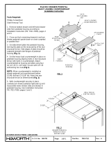
Dual VersiCharge Mounting (Back-to-Back) using US2:VCPOSTGRY2
. All steps for single unit mounting shall be repeated on two () sides of the pedestal.
Figure . Dual mounting
- back view
Figure . Dual mounting
- left-side view
Figure . Dual mounting
- front view
Figure . Dual mounting
- right-side view
VersiCharge™ Dual Post and Cable Management System

Single/Dual Post and Cable System Installation using US2:VCPOSTGRY2 and
US2:VCCMSSP
. Align the square Cord Retractor body along the right side of the charging station.
. The upper retractor bracket is threaded and slides the length of the retractor post. Locate the ⅝” hole located at the top
of the pedestal on right side, align unit with mounting bracket in place. Place the washers on the /” x ¾” bolt before
inserting to space the bracket bolt so it is fully threaded into the upper bracket but DOES NOT penetrate the retractor post.
Insert bolt with washer from the inside of the post and tighten, torque to . lb.-in. Use silicone sealer between the
pedestal post and retractor post to make it liquid-tight.
. Make sure unit is plumb with hole at the baseplate, and anchor to baseplate with /” anchor bolt.
. Tighten all bolts. Seal pedestal bolt hole with an outdoor rated silicone to ensure it is watertight.
. Install cord clamp in a location on the cord which keeps it off the ground when the connector is in the ‘parked’ or
‘holstered’ position. Use black electrical tape to take up any gap between the cord and the inside of the clamp. Tighten the
clamp enough to not allow the cord to slide.
Figure . Single/Dual
mounting with Cable
System - right-side view
Figure . Single/Dual
mounting with Cable
System - left-side view
Figure . Single/Dual
mounting with Cable
System - front view
Figure . Single/Dual
mounting with Cable
System - back view
VersiCharge™ Dual Post and Cable Management System

Dual Cord Retractor Mounting using US:VCPOSTGRY and US:VCCMSSP parts
. Steps for single cord retractor shall be repeated on two () sides of the pedestal.
Installing the Access Cover and Top Cap
Once all the above steps are complete and all screws, bolts, fittings, etc. are tight, place a thin bead of silicone sealer around
the perimeter of the access plate and screw the plate onto the post using the provided stainless torx head screws. Wipe off any
excess sealer. Place a generous bead of silicone sealer around the perimeter of the top cap and insert the cap into the pedestal
post. A rubber mallet is recommended to properly seat the top cap. Wipe off any excess sealer.
Figure . Dual Cord
Retractor Mounting
- right or left view
Figure . Dual Cord
Retractor Mounting
- front view
Figure . Dual Cord
Retractor Mounting
- back view
Figure . Dual Cord Retractor Mounting - top view
VersiCharge™ Dual Post and Cable Management System

Power the Station(s)
1. Turn on the power feed to the station(s) and test as per the VersiCharge installation manual.
VersiCharge™ Dual Post and Cable Management System

© by Siemens Industry, Inc.
Legal Manufacturer
Siemens Industry, Inc.
Parkway Ln.
Peachtree Corners, GA
United States of America
Telephone: + () -
Engineering Doc No: R-R
Article No. SIDS-T--AUS
This document contains a general description of available technical
options only, and its effectiveness will be subject to specific variables
including field conditions and project parameters. Siemens does not
make representations, warranties, or assurances as to the accuracy or
completeness of the content contained herein. Siemens reserves the
right to modify the technology and product specifications in its sole
discretion without advance notice.
/