Page is loading ...

R
www.quadrafi re.com 7034-106G November 22, 2011
MT. VERNON PELLET STOVE
ADVANCED ENERGY (AE)
O-T L
Tested and
Listed by
Portland
Oregon USA
OMNI-Test Laboratories, Inc.
CUS
Owner’s Manual
Installation and
Operation
Models:
MTVERNON-AE-MBK
MTVERNON-AE-PMH
MTVERNON-AE-CSB
MTVERNON-AE-CWL
Tested and approved for wood pellets, shelled fi eld
corn, wheat and black oil sunfl ower seeds. Burning
of any other type of fuel voids your warranty.
CAUTION
DO NOT DISCARD THIS MANUAL
NOTICE
• Important operating and
maintenance instruc-
tions included.
• Leave this manual with
party responsible for use
and operation.
• Read, understand and
follow these instruc-
tions for safe installa-
tion and operation.
DO NOT
DISCARD
WARNING
Please read this entire manual
before installation and use of this
pellet fuel-burning room heater.
Failure to follow these instructions
could result in property damage,
bodily injury or even death.
• Do not store or use gasoline or other fl am-
mable vapors and liquids in the vicinity of this
or any other appliance.
• Do not overfi re - If any external part starts to
glow, you are overfi ring. Reduce feed rate.
Overfi ring will void your warranty.
• Comply with all minimum clearances to com-
bustibles as specifi ed. Failure to comply may
cause house fi re.
Check building codes prior to installation.
• Installation MUST comply with local, regional, state and national
codes and regulations.
• Consult local building, fi re offi cials or authorities having jurisdic-
tion about restrictions, installation inspection, and permits.
CAUTION
WARNING
Hot glass will cause burns.
• Do not touch glass until it is cooled
• NEVER allow children to touch glass
• Keep children away
• CAREFULLY SUPERVISE children in same room as
fi replace.
• Alert children and adults to hazards of high
temperatures.
High temperatures may ignite clothing or other
fl ammable materials.
• Keep clothing, furniture, draperies and other fl ammable
materials away.
HOT SURFACES!
Glass and other surfaces are
hot during operation AND
cool down.

Page 2 7034-106G November 22, 2011
R
Mt. Vernon Pellet Stove (AE)
Hearth & Home Technologies welcomes you to our tradi-
tion of excellence! In choosing a Quadra-Fire appliance,
you have our assurance of commitment to quality, durabil-
ity, and performance.
This commitment begins with our research of the market,
including ‘Voice of the Customer’ contacts, ensuring we
make products that will satisfy your needs. Our Research
and Development facility then employs the world’s most
advanced technology to achieve the optimum operation of
our stoves, inserts and fi replaces. And yet we are old-fash-
ioned when it comes to craftsmanship. Each unit is meticu-
lously fabricated and surfaces are hand-fi nished for lasting
beauty and enjoyment. Our pledge to quality is completed
as each model undergoes a quality control inspection.
We wish you and your family many years of enjoyment in
the warmth and comfort of your hearth appliance.
Thank you for choosing Quadra-Fire.
LOCATION OF SERIAL NUMBER / SAFETY LABEL: Back of Stove
Test Lab & Report No.
Mfg Date
Model NameSerial No.
SAMPLE
CAUTION
:
HOT WHILE IN
OPERATION DO NOT TOUCH,
KEEP CHILDREN, CLOTHING
AND FURNITURE AWAY.
ATTENTION:
CHAUD LORS DE L'OPÉRATION. NE PAS
TOUCHER. GARDEZ LES ENFANTS ET LES VÊTEMENTS
LOIN DE L'ESPACE DÉSIGNÉ DE L'INSTALLATION. LE
CONTACT PEUT CAUSER DES BRÛLURES À LA PEAU. VOIR
ESPACES LIBRES MINIMUM DES MATÉRIAUX COMBUSTIBLES:
INSTALLATION DE L’ALCÔVE
Une hauteur minimum de l'alcôve:
43 in.(
1092mm)
Une hauteur minimum m
ur de côté
de l'alcôve:
6 in. (152mm)
Une épaisseur
minimum m
ur de côté
de l'alcôve:
40 in. (1016mm)
La profondeur maximum de l'alcôve:
36 in. (914mm)
Note 1: Dans les installations résidentielles, lorsque les pièces
TPVNT-MV, (dessus de l'adapteur de ventilation 3 in. - 3 in.) et
812-3570 (le ressaut de l'adapteur 3 in. - 6 in.), un tuyau connecteur
de 6 in. pour mur simple de calibre 24 peut être utilisé.
Note 2: Pour l'installation dans les maisons préfabriquées, lorsque
les pièces TPVNT-MV, (dessus de l'adapteur de ventilation 3 in. - 3
in.) et 812-3570 (le ressaut de l'adapteur 3 in. - 6 in.), utilisez un
tuyau connecteur enregistré pour mur double. Un assemblage d'air
extérieur (pièce 811-0872), doit être utilisé pour l'installation dans
les maisons préfabriquées.
PROTECTION DU SOL
A
B
G
G
D
E
F
C
C
A 2 in (51mm)
B 6 in. (152mm)
C 2 in. (51mm)
D 3 in. (76mm)
E 6 in. (152mm)
F 8 in. (203mm)
G 3 in. (76mm)
I*
J
J
K
I* = 8 in. (200mm)
J = 18 in. (450mm)
K = 8 in. (200mm)
G
G
D
E
F
C
C
A
B
2011
2012
2013
JAN FEB MAR APR MAY JUN
JULY AUG SEPT OCT NOV DEC
Mt. Vernon Pellet
Stove AE
Report / Rapport
061-S-68-6
ALCOVE INSTALLATION:
Min. Alcove Height:
43 in. (
1092mm)
Min. Alcove Side Wall:
6 in. (152mm)
Min. Alcove Width:
40 in. (1016mm)
Max. Alcove Depth:
36 in. (914mm)
A 2 in (51mm)
B 6 in. (152mm)
C 2 in. (51mm)
D 3 In (76mm)
E 6 in (152mm)
F 8 in.(203mm)
G 3 in. (76mm)
MINIMUM CLEARANCES TO COMBUSTIBLE MATERIALS
FLOOR PROTECTION
Use a non-combustible floor protector, extending
beneath heater and to the front/sides/rear as indicated.
Measure front distance (K) from the surface of the
glass door.
I* = 2 in. (51mm)
J = 2 in. (51mm)
K = 6 in. (152mm)
I*
J
J
K
Note 1:
In residential
installations, when using
Parts TPVNT-MV, (3 in. - 3
in. Top Vent Adapter) and
812-3570 (3 in. - 6 in. Offset
Adapter), 24 gauge 6 in.
single wall flue connector
may be used.
*
Non-combustible floor protection must extend beneath the
flue pipe when installed with horizontal venting or under the
Top Vent Adapter with vertical installation. RECOMMENDED
IN USA
SERIAL NO.
/
NUMÉRO DU
007001
Listed Solid Fuel Room Heater/Pellet
Type Stove.
Also suitable for Mobile
Home Installation. This appliance has
been tested and listed for use in
Manufactured Homes in accordance with
OAR 814-23-9000 through 814-23-909.
Tested to: ASTM E1509-04, ULC S627-00,
ULC/ORD-C1482-M1990 Room Heating
Pellet Burning Type, (UM) 84-HUD FOR USE
ONLY WITH PELLETIZED WOOD. See Owner’s
Manual for other fuel options.
Input Rating: 60,000 Btu's/hr. Electrical
Rating:
115 VAC, 60 Hz, Start 5 Amps, Run
1.25 AMPS.
Route power cord away from unit. Do not
route cord under or in front of appliance.
DANGER:
Risk of electrical shock.
Disconnect power supply before servicing.
Replace glass only with 5mm ceramic
available from your dealer. To start, set
thermostat above room temperature, the
stove will light automatically. To shutdown,
set thermostat to below room temperature.
For further instruction refer to owner's
manual.
Keep viewing and ash removal
doors tightly closed during operation.
DO NOT REMOVE THIS LABEL
NE PAS ENLEVER L’
É
QUETTE 7034-107E
Note 2: In manufactured home
installation, when using Part
TPVNT-MV, (3 in. - 3 in. Top Vent
Adapter) and 812-3570 (3 in. - 6 in.
Offset Adapter), use listed double
wall flue connector. An Outside Air
Kit (Part 811-0872), must be used
with manufactured home installation.
1445 Highway North,
Colville, WA 99114
www.quadrafire.com
Manufactured by / Fabriqu
é
par:
Made in the USA
Fait-Aux
É
tats-Unix
O-T L
Tested and
Listed by
Portland
Oregon USA
OMNI-Test Laboratories, Inc.
CUS
NOTE: Consult insurance carrier, local building inspector, fi re
offi cials or authorities having jurisdiction over restrictions,
installation inspection and permits.

R
November 22, 2011 7034-106G Page 3
Mt. Vernon Pellet Stove (AE)
TABLE OF CONTENTS
Safety Alert Key:
• DANGER! Indicates a hazardous situation which, if not avoided will result in death or serious injury.
• WARNING! Indicates a hazardous situation which, if not avoided could result in death or serious injury.
• CAUTION! Indicates a hazardous situation which, if not avoided, could result in minor or moderate injury.
• NOTICE: Indicates practices which may cause damage to the appliance or to property.
Section 1: Listing and Code Approvals
A. Appliance Certifi cations ......................4
B. Mobile Home Approved ......................4
C. Glass Specifi cations ............................4
D. Electrical Rating ..................................4
E. Specifi cations ......................................4
Section 2: Getting Started
A. Design, Installation & Location
Considerations ....................................5
B. Thermostat Wall Control Location ......6
C. Tools & Supplies Needed ...................6
D. Inspect Appliance & Components.......6
E. Pre-Use Check List .............................6
Section 3: Dimensions & Clearances
A. Appliance Dimensions ........................7
B. Clearances to Combustibles ...............8
C. Hearth Pad Requirements ..................8
Section 4: Vent Information
A. Venting Termination Requirements ....9
B. Avoiding Smoke and Odors ................10
C. Negative Pressure ...............................11
D. Draft .....................................................11
E. Chimney & Exhaust Connection .........12
F. Equivalent Meter of Pipe .....................12
G. Pipe Selection Chart ............................13
Section 5: Venting Systems
A. Alcove .................................................14
B. Through the Wall .................................15
C. Vertical into Class A Chimney .............16
D. Through the Wall & Vertical-Exterior ...16
E. Vertical-Interior ....................................16
F. Masonry ..............................................17
G. Alternate Masonry ...............................17
Section 6: Mobile Home Installation ............18
Section 7: Appliance Set-Up
A. Leg Leveling System ..........................19
B. Outside Air Kit .....................................19
C. Top Vent Adapter ................................20
D. Rear Vent Adapter ..............................20
E. Log Set Placement ..............................21
F. Thermostat Wall Control Installation ...22
Section 8: Operating Instructions
A. Fire Safety .....................................23
B. Combustible/Non-Combustile ........23
C. Fuel Size, Material & Storage .............23-24
D. General Operation Information ...........24
E. Before Your First Fire .........................25
F. Filling the Hopper with Fuel ................25
G. Starting Your First Fire ........................25
H. Fire Characteristics & Flame Height
Adjustment ..........................................25
I. Battery Back-Up System.....................26
J. Clear Space ........................................26
K. Ignition Cycles ....................................27-28
L. Quick Start Guide ...............................29-30
M. Frequently Asked Questions...............31
Section 9: Troubleshooting ............................32
Section 10: Maintaining & Servicing Appliance
A. Proper Shutdown Procedures .............33
B. Quick Reference Maintenance Chart ..33
C. General Maintenance & Cleaning .......34-38
D. Soot or Creosote Fire ..........................38
E. High Ash Fuel Content Maintenance ..39
F. Baffl e Removal ....................................39
G. Convection Blower Replacement ........40
H. Combustion Blower Replacement .......41
I. Glass Replacement .............................41
Section 11: Reference Materials
A. Component Functions.........................42-43
B. Component Locations .........................44
C. Exploded Drawings .............................45-46
D. Service Parts & Accessories ...............47-51
E. Service & Maintenance Log ................52-53
F Warranty Policy ...................................54-55
G. Contact Information .............................56

Page 4 7034-106G November 22, 2011
R
Mt. Vernon Pellet Stove (AE)
1Listing and Code Approvals
A. Appliance Certifi cation E. BTU & Effi ciency Specifi cations
Model Mt. Vernon Pellet Stove AE
Laboratory OMNI Test Laboratories, Inc.
Report No. 061-S-68-6
Type Solid Fuel Room Heater/Pellet Fuel
BurningType
Standard ASTM E1509-04, ULC S627-00 and
ULC/ORD-C1482-M1990 Room Heater
Pellet Fuel Burning type and (UM) 84-
HUD, Mobile Home Approved.
FCC Complies with Part 15 of FCC Rules.
Operation is subject to the following
two conditions: (1) this device may not
cause harmful interference, and (2) this
device must accept any interference
received, including interference that
may cause undesired operation.
Emissions Rating: EPA Compliance
*BTU Output: 14,620 - 60,200 / hr
Effi ciency: 81.4% - 83.6%
Heating Capacity: 2,400 - 3,800 square feet depend-
ing on climate zone
Hopper Capacity: 81 lbs
Fuels: Pellets, Shelled Field Corn, Wheat
and Black Sunfl ower Seeds
Shipping Weight: 429 lbs
C. Glass Specifi cations
This appliance is equipped with 5mm ceramic glass. Replace
glass only with 5mm ceramic glass. Please contact your
dealer for replacement glass.
This appliance is approved for mobile home installations
when not installed in a sleeping room and when an outside
combustion air inlet is used.
The structural integrity of the mobile home fl oor, ceiling, and
walls must be maintained.
The appliance must be properly grounded to the frame of
the mobile home and use only Listed pellet vent Class “L”
or “PL” connector pipe.
A Quadra-Fire Outside Air Kit must be installed in a mobile
home installation. You must order the Outside Air Kit sepa-
rately.
B. Mobile Home Approved
NOTICE: This installation must conform with local codes.
In the absence of local codes you must comply with the
ASTM E1509-04, ULC S627-00, (UM) 84-HUD and
ULC/ORD-C-1482.
D. Electrical Rating
115 VAC, 60 Hz, Start 5 Amps, Run 1.25 Amps
NOTICE: Hearth & Home Technologies, manufacturer
of this appliance, reserves the right to alter its prod-
ucts, their specifi cations and/or price without notice.
Quadra-Fire is a registered trademark
of Hearth & Home Technologies.
WARNING! Risk of Fire! Hearth & Home Technologies dis-
claims any responsibility for, and the warranty and agency
listing will be voided by the above actions.
DO NOT:
• Install or operate damaged appliance
• Modify appliance
• Install other than as instructed by Hearth & Home
Technologies
• Operate the appliance without fully assembling all
components
• Overfi re
• Install any component not approved by Hearth &
Home Technologies
• Install parts or components not Listed or approved.
Improper installation, adjustment, alteration, service or
maintenance can cause injury or property damage.
For assistance or additional information, consult a qualifi ed
installer, service agency or your dealer.
Note: This appliance is also approved for installation
into a shop.
*BTU will vary, depending on the type of fuel you use in
your appliance. Consult your Quadra-Fire dealer for best
results.

R
November 22, 2011 7034-106G Page 5
Mt. Vernon Pellet Stove (AE)
2Getting Started
Marginal Location:
• Below peak
Location NOT recommended:
• Not the highest point of the roof
• Wind loading possible
Multi-level Roofs
Windward
Leeward
Recommended:
Outside Air Intake
on windward side
NOT recommended:
Outside Air Intake
on leeward side
Recommended Location:
• Above peak
Recommended:
• Insulated exterior chase
in cooler climates
Recommended Location:
• Above peak
• Inside heated space
Location NOT recommended:
• Too close to tree
• Below adjacent structure
• Lower roof line
• Avoid outside wall
Marginal Location:
• Wind loading possible
Figure 5.1
A
.
Design, Installation & Location Considerations
WARNING! Risk of Fire Damaged parts could impair safe
operation. Do NOT install damaged, incomplete or substitute
components.
1. Appliance Location
NOTICE: Check building codes prior to installation.
• Installation MUST comply with local, regional, state and
national codes and regulations.
• Consult insurance carrier, local building inspector, fi re
offi cials or authorities having jurisdiction over restrictions,
installation inspection and permits.
It is a good idea to plan your installation on paper, using exact
measurements for clearances and fl oor protection, before
actually beginning the installation. Location of the appliance
and chimney will affect performance.
Consideration must be given to:
• Safety, convenience, traffi c fl ow
• Placement of the chimney and chimney connector and to
minimize the use of chimney offsets.
• Place the appliance where there will be a clear passage
for a Listed chimney through the ceiling and roof (vertical)
or through exterior wall (horizontal).
• Installing the required outside air kit will affect the location
of the vent termination.
When locating vent and venting termination, the ideal loca-
tion is to vent above roof line when possible. This minimizes
the affects of wind loading.
CAUTION! If burning shelled fi eld corn, you must use ap-
proved venting specifi cally designed for corn to prevent
corrosion or degradation. Follow the instructions from the
venting manufacturer.
Since pellet exhaust can contain ash, soot or sparks, you
must consider the location of:
• Windows
• Air Intakes
• Air Conditioner
• Overhang, soffi ts, porch roofs, adjacent walls
• Landscaping, vegetation
• Horizontal or vertical vent termination
2. Floor Support
The supporting fl oor under the appliance must be able
to handle the weight of the appliance, fuel load and the
weight of the chimney.
Ensure that your fl oor will suport these weights prior to in-
stallation. Add suffi cient additional support to meet this
weight requirment prior to installation. The weight of the
appliance is 429 lbs.

Page 6 7034-106G November 22, 2011
R
Mt. Vernon Pellet Stove (AE)
• Installation and use of any damaged appliance.
• Modifi cation of the appliance.
• Installation other than as instructed by Hearth & Home
Technologies.
• Installation and/or use of any component part not
approved by Hearth & Home Technologies.
• Operating appliance without fully assembling all
components.
• Operating appliance without legs attached (if supplied
with unit).
• Do NOT Overfi re
Or any such action that may cause a fi re hazard.
WARNING
Hearth & Home Technologies disclaims any
responsibility for, and the warranty will be
voided by, the following actions:
Reciprocating Saw
Channel Locks
Hammer
Phillips Screwdriver
Tape Measure
Plumb Line
Level
Framing Material
Hi-temp Caulking Material
Gloves
Safety Glasses
Framing Square
Electric Drill & Bits (1/4”)
1/4” Self-Tapping Screws
May also need:
Vent Support Straps
Venting Paint
Tools and building supplies normally required
for installation, unless installing into an existing
masonry fi replace:
C. Tools And Supplies Needed
E. Pre-Use Check List
1. Place the appliance in a location near the
fi nal installation area and follow the proce-
dures below:
2. Open the appliance and remove all the parts
and articles packed inside the Component
Pack.
Inspect all the parts and glass for shipping
damage. Contact your dealer if any irregulari-
ties are noticed.
Remove rubber band from ash pan installed for
shipping purposes only.
3. All safety warnings have been read and fol-
lowed.
4. This Owner’s Manual has been read.
5. Floor protection requirements have been met.
6. Venting is properly installed.
7. The proper clearances from the appliance and
chimney to combustible materials have been
met.
8. The masonry chimney is inspected by a profes-
sional and is clean, or the factory built metal
chimney is installed according to the manufac-
turer’s instructions and clearances.
9. The chimney meets the required minimum
height.
10.
All labels have been removed from the glass
door.
11. Plated surfaces have been wiped clean, if
applicable.
12. Wall Control Thermostat has been installed.
13. A power outlet is available nearby.
14. A good quality surge protectory is highly recom-
mended to protect the electronics.
B. Thermostat Wall Control Location
The thermostat wall control’s location will have some affect
on the appliance’s operation.
• Maximum wire length from appliance is 100 feet (30.48m)
continuous unspliced wire. Recommended 20 gauge wire,
solid copper .
• When located close to the appliance, it may require a
slightly higher temperature setting to keep the rest of the
house comfortable.
• When located in an adjacent room or on a different fl oor
level, you will notice higher temperatures near the appli-
ance.
CAUTION!
The wall control is an integral part of the appli-
ance. No other wall control or thermostat can be substi-
tuted.
D. Inspect Appliance and Components
WARNING! Risk of Fire! Damaged parts could impair safe
operation. Do NOT install damaged, incomplete or substitute
components.
• Open the appliance and remove all the parts and articles
packed inside the Component Pack. Inspect all the parts
and glass for shipping damage.
• Report to your dealer any parts damaged in shipment.
•
All labels have been removed from the glass door.
•
Plated surfaces have been wiped clean with a soft cloth,
if applicable.
• Read all the instructions before starting the installation.
Follow these instructions carefully during the
installation to ensure maximum safety and benefi t.
• Follow pipe manufacturer instructions for installation
and air clearance requirments.

R
November 22, 2011 7034-106G Page 7
Mt. Vernon Pellet Stove (AE)
3Dimensions and Clearances
A. Appliance Dimensions
Figure 7.4 - Front View
Figure 7.1 - Top View with Top Vent Adapter
and 3 to 6 in (76-152mm) Adapter
Figure 7.5 - Side View
Figure 7.2 - Side View with Top Vent
Adapter and 3 to 6 in (76-152mm)
Offset Adapter.
29-3/6 in.
(741mm)
31-1/6 in.
(788mm)
C
L
5-13/16 in.
(147mm) 3-13/16 in.
(97mm)
14-1/16 in.
(357mm)
2-9/16 in.
(65mm)
28-7/16 in.
(722mm)
32-5/16 in.
(821mm)
28-1/8 in. (714mm)
20 in.
(508mm)
19-9/16 in.
(497mm)
29-1/16 in. (738mm)
26-7/8 in. (683mm)
18-1/2 in. (470mm)
C
L
10-3/8 in.
(264mm)
C
L
Figure 7.3 - Top View

Page 8 7034-106G November 22, 2011
R
Mt. Vernon Pellet Stove (AE)
Straight Back Against Wall Inches Millimeters
ABack Wall to Appliance 2 51
BSide Wall to Appliance 6 152
Corner Installation Inches Millimeters
CWalls to Appliance 2 51
Vertical Installation Inches Millimeters
DBack Wall to Flue Pipe 3 76
ESide Wall to Appliance 6 152
FBack Wall to Appliance 8 203
Installations with:
3 to 3 inch Top Vent Adapter and
3 to 6 inch Offset Adapter Kit
Corner Installation Inches Millimeters
GSide Wall to Flue Pipe 3 76
Alcove Installation Inches Millimeters
Minimum Alcove Height 43 1092
Minimum Alcove Side Wall 6 152
Minimum Alcove Width 40 1016
Maximum Alcove Depth 36 914
B. Clearances to Combustibles (UL and ULC)
D
E
F
A
B
*L Exception for Horizontal Installations:
USA INSTALLATIONS: A
non-combustible fl oor protec-
tion is required extending beneath the fl ue pipe when
installed with horizontal venting or under the Top Vent
Adapter with vertical installation.
CANADA INSTALLATIONS: A
non-combustible fl oor
protection extending beneath the fl ue pipe is reccom-
mended with horizontal venting or under the Top Vent
Adapter with vertical installation.
Must extend 2 inches (51mm) beyond each
side of pipe (shaded area)
Fire Risk.
Comply with all minimum clearances to
combustibles as specifi ed.
WARNING
Failure to comply may cause house fi re.
NOTE:
• Illustrations refl ect typical installations and are FOR
DESIGN PURPOSES ONLY.
• Illustrations/diagrams are not drawn to scale.
• Actual installation may vary due to individual design
preference.
C
C
G
G
C. Hearth Pad Requirements (UL and ULC)
L*
K
K
M
Use a non-combustible fl oor protector, extending beneath
appliance and to the front, sides and rear as indicated.
Measure front distance “M” from the surface of the glass
door.
Hearth Pad Requirements Inches Millimeters
KSides 2 51
L* Back 2 51
MFront 6 152

R
November 22, 2011 7034-106G Page 9
Mt. Vernon Pellet Stove (AE)
4Vent Information
A. Venting Termination Minimum Requirements
J or K
X
V
M
I
H
A
V
G
B
V
V
A
B
V
FV
C
B
B
E
L
V
D
V
Electrical
Service
V
N
VN
V
N
N
V
Inside Corner
FIXED
CLOSED
OPEN
OPEN
FIXED
CLOSED
VX
G
G
Termination Cap Air Supply Inlet Gas Meter Restricted Area
O
P
Figure 9.1
NOTICE:
Termination must exhaust above air inlet elevation.
• It is recommended that at least 60 inches (1.52m) of vertical
pipe be installed when appliance is vented directly through a
wall. This will create a natural draft, which will help prevent
the possibility of smoke or odor venting into the home during
a power outage.
• It will also keep exhaust from causing a nuisance or hazard
by exposing people or shrubs to high temperatures.
• The safest and preferred venting method is to extend the
vent vertically through the roof or above the roof.
A12 in. Above Finish Grade (the grade surface
must be a non-combustible material
B12 in.
48 in. no OAK
Open door or window: below or to the side
B12 in. Open door or window: above
C6 in. Permanently closed window: above, below
or to the side
D18 in.
36 in. no OAK
Vertical clearance to a ventilated soffi t
located above the terminal within a hori-
zontal distance of 2 ft from the center-line
of the terminal
E12 in. Clearance to unventilated soffi t
F12 in. Clearance to outside corner
G12 in. Clearance to inside corner
H36 in. Above gas meter/regulator measured from
horizontal center-line of regulator
I36 in. USA
72 in. Canada
Clearance to service regulator vent outlet
J12 in.
48 in. no OAK
Clearance to non-mechanical air supply
inlet to the building or the combustions air
inlet to any other appliance
K10 ft horizontal
3 ft vertical
Clearance to mechanical air supply
L7 ft. Above paved sidewalk, paved driveway
located on public property
M12 in. Under an open veranda, porch, deck or
balcony
NSee Note
below*
Electric service: above, below or to the
side (location must not obstruct or interfere
with access)
O24 in. Adjacent building, fences and protruding
parts of the structure
P12 in. Clearance above roof line for vertical
terminations
All minimum clearances are listed with an Outside Air Kit (OAK) installed, unless otherwise noted in table below.
24 in. Above grass, top of plants, wood or any other com-
bustible
12 in.
36 in. no OAK
Clearance from any forced air intake of other appli-
ance
12 in. Clearance horizontally from combustible wall
15 in. Vented directly through a wall, minimum length of
horizontal pipe
6 in. horizontal
12 in. vertical
Minimum horizontal or vertical terminations must
protrude from wall
*NOTE: Consult local building, fi re offi cials or authorities having jurisdic-
tion. Local codes or regulations may require different clearances.
NOTICE:
Do NOT Terminate Vent:
• In any location that will allow fl ue gases or soot from enter-
ing or staining the building
• In any location which could create a nuisance or hazard
• In any enclosed or semi-enclosed area such as a carport,
garage, attic, crawl space, under a sun deck or porch,
narrow walkway
• Closely fenced area, or any location that can build up
a concentration of fumes such as a stairwell, covered
breezeway, etc.

Page 10 7034-106G November 22, 2011
R
Mt. Vernon Pellet Stove (AE)
B. Avoiding Smoke and Odors
Negative Pressure, Shut-Down and Electrical Power
Failure
To reduce the probability of back-drafting or burn-back in
the pellet appliance during power failure or shut down con-
ditions, it must be able to draft naturally without exhaust
blower operation.
Negative pressure in the house will resist this natural draft
if not accounted for in the pellet appliance installation.
Heat rises in the house and leaks out at upper levels. This
air must be replaced with cold air from outdoors which
fl ows into lower levels of the house.
Vents and chimneys into basements and lower levels of the
house can become the conduit for air supply and reverse
under these conditions.
Outside Air
An outside air kit is recommended in all installations. The
Outside Air Kit must be ordered seperately.
Per national building codes, consideration must be given
to combustion air supply to all combustion appliances.
Failure to supply adequate combustion air for all appli-
ance demands may lead to backdrafting of those and other
appliances.
When the appliance is roof vented (strongly recommended):
The air intake is best located on the exterior wall ori-
ented towards the prevailing wind direction during the
heating season.
When the appliance is side-wall vented:
The air intake is best located on the same exterior wall
as the exhaust vent outlet and located lower on the wall
than the exhaust vent outlet.
The outside air supply kit can supply most of the demands
of the pellet appliance, but consideration must be given to
the total house demand.
House demand may consume the air needed for the appli-
ance. It may be necessary to add additional ventilation to
the space in which the pellet appliance is located.
Consult with your local HVAC professional to determine the
ventilation demands for your house.
Vent Confi gurations
To reduce probability of reverse drafting during shut-down
conditions Hearth & Home Technologies strongly recom-
mends:
• Installing the pellet vent with a minimum vertical run
of 5 feet (1.52m). Preferably terminating above the
roof line.
• Installing the outside air kit at least 4 feet (1.22m)
below the vent termination.
To prevent soot damage to exterior walls of the house and
to prevent re-entry of soot or ash into the house:
• Maintain specifi ed clearances to windows, doors and
air inlets, including air conditioners.
• Vents should not be placed below ventilated soffi ts.
Run the vent above the roof.
• Avoid venting into alcove locations.
• Vents should not terminate under overhangs, decks
or onto covered porches.
• Maintain minimum clearance of 12 inches (305mm)
from the vent termination to the exterior wall. If you
see deposits developing on the wall, you may need
to extend this distance to accommodate your installa-
tion conditions.
CAUTION
• DO NOT CONNECT THIS UNIT TO A CHIMNEY FLUE
SERVICING ANOTHER APPLIANCE.
• DO NOT CONNECT TO ANY AIR DISTRIBUTION DUCT
OR SYSTEM.
Optional Battery Back-Up
Hearth & Home Technologies supplies an optional battery
back-up system that operates the appliance during power
failure conditions to prevent smoking. In shutdown mode,
the battery back-up will not prevent smoking. See Section
8 for details.
Hearth & Home Technologies assumes no responsibility for,
nor does the warranty extend to, smoke damage caused
by reverse drafting of pellet appliances under shut down or
power failure conditions.

R
November 22, 2011 7034-106G Page 11
Mt. Vernon Pellet Stove (AE)
Negative pressure results from the imbalance of air available
for the appliance to operate properly. It can be strongest in
lower levels of the house.
Causes include:
• Exhaust fans (kitchen, bath, etc.)
• Range hoods
• Combustion air requirements for furnaces, water heaters
and other combustion appliances
• Clothes dryers
• Location of return-air vents to furnace or air conditioning
• Imbalances of the HVAC air handling system
• Upper level air leaks such as:
- Recessed lighting
- Attic hatch
- Duct leaks
To minimize the effects of negative air pressure:
• Install the outside air kit with the intake facing prevailing
winds during the heating season
• Ensure adequate outdoor air for all combustion appliances
and exhaust equipment
• Ensure furnace and air conditioning return vents are not
located in the immediate vicinity of the appliance
• Avoid installing the appliance near doors, walkways or
small isolated spaces
• Recessed lighting should be a “sealed can” design
• Attic hatches weather stripped or sealed
• Attic mounted duct work and air handler joints and seams
taped or sealed
WARNING! Risk of Asphyxiation! Negative pressure can
cause spillage of combustion fumes and soot.
C. Negative Pressure
Draft is the pressure difference needed to vent an ap-
pliance successfully. When an appliance is drafting suc-
cessfully, all combustion byproducts are exiting the home
through the chimney.
Install through the warm airspace enclosed by the building
envelope. This helps to produce more draft, especially dur-
ing lighting and die-down of the fi re.
Considerations for successful draft include:
• Preventing negative pressure
• Location of appliance and chimney
NOTICE: Hearth & Home Technologies assumes no
responsibility for the improper performance of the chimney
system caused by:
• Inadequate draft due to environmental conditions
• Downdrafts
• Tight sealing construction of the structure
• Mechanical exhausting devices
D. Draft

Page 12 7034-106G November 22, 2011
R
Mt. Vernon Pellet Stove (AE)
E. Chimney and Exhaust Connection
1. Chimney & Connector: Use 3 or 4 inch (76-102mm)
diameter type "L" or "PL" venting system. It can be vented
vertically or horizontally.
2. Mobile Home: Approved for all Listed pellet vent. If using
the 3 inch (76mm) vertical Top Vent Adapter Kit or the 3
to 6 inch (76-152mm) Top Vent Offset Adapter, use Listed
double wall fl ue connector. A Quadra-Fire Outside Air Kit
must be used with manufactured home installations.
3. Residential: The 3 inch (76mm) vertical Top Vent Adapter
Kit and the 3 to 6 inch (76-152mm) Top Vent Offset Adapter
are tested to use 24 gauge single wall fl ue connector or
Listed double wall fl ue connector to Class A Listed metal
chimneys, or masonry chimneys meeting International
Residential Code standards for solid fuel appliances.
4. INSTALL VENT AT CLEARANCES SPECIFIED BY THE
VENT MANUFACTURER.
5. Secure exhaust venting system to the appliance with at
least 3 screws. Also secure all connector pipe joints with
at least 3 screws through each joint.
6. DO NOT INSTALL A FLUE DAMPER IN THE EXHAUST
VENTING SYSTEM OF THIS UNIT.
7. DO NOT CONNECT THIS UNIT TO A CHIMNEY FLUE
SERVING ANOTHER APPLIANCE.
NOTE: All pipe must be welded seam pipe whenever
possible. Seal pipe joints with high temperature silicone
(500°F [260°C] minimum rated only).
NOTE: If burning shelled field corn, you must use
approved venting specifi cally designed for corn. Follow
the instructions from the venting manufacturer.
The table below can help you calculate the equivalent feet
of pipe which is a method used to determine pellet vent size.
Figure 12.1.
F. Equivalent Feet of Pipe
2 ft.
2 ft.
3 ft.
2 ft.
Example of 3 Elbow-Rear Vent Termination Calculation
Figure 12.1
Pellet Venting
Component
# of
Elbows
Feet of
Pipe
Multiplied
By
Equivalent
Feet
Components
Equivalent Feet
90o Elbow or Tee 3 X 515
45o Elbow X3
Horizontal Pipe 7 X 17
Vertical Pipe 2 X 0.5 1
Total Equivalent Feet 23
Note: This is a generic example and is not
intended to represent any specifi c fuel type.
• Only LISTED venting components may be used.
• NO OTHER vent components may be used.
• Substitute or damaged vent components may impair
safe operation.
WARNING! RISK OF FIRE!
WARNING! RISK OF INJURY OR PROPERTY
DAMAGE!
• Improper installation, adjustment, alteration, service or
maintenance can cause injury or property damage.
• Refer to the owner’s information manual provided with this
appliance.
• For assistance or additional information consult a qualifi ed
installer, service agency or your dealer.
Vent surfaces get HOT, can cause burns
if touched. Non-combustible shielding or
guards may be required.
WARNING

R
November 22, 2011 7034-106G Page 13
Mt. Vernon Pellet Stove (AE)
G. Pipe Selection Chart
Do NOT pack insulation or other combustibles between
fi restops.
• ALWAYS maintain specifi ed clearances around venting
and fi restop systems.
• Install fi restops as specifi ed.
Failure to keep insulation or other material away from vent
pipe may cause fi re.
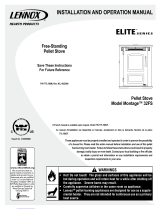
Figure 13.1
3 in. or 4 in. (76mm or 102mm) Diameter Pipe
Equivalent Pipe
Length In Feet
ALTITUDE IN THOUSANDS OF FEET
0
20
30
1 2 3 4 5 6 7 8 9 10
4 in. (102mm) Diameter Pipe Only
10
Example 1
Example 2
Example 1: If the equivalent length of pipe is 23 feet (7m) with altitude
of 8,000 feet (2438m) you must use 4 inch (102mm) diameter type “L”
or “PL” vent.
Example 2: If the equivalent length of pipe is 12 feet (3.7m) with altitude
of 6,000 feet (1829m) you may use 3 or 4 inch (76 to 102mm) diameter
type “L” or “PL” vent.
The chart will help you in determining proper venting size
according to the equivalent feet of pipe calculated previously
and the altitude above sea level of this installation.
Figure 13.1.
a. Locate the calculated equivalent feet of pipe on the verti-
cal left side of the chart.
b. Move to the right horizontally on the chart until you reach
your altitude above sea level.
c. If you fall below the diagonal line, 3 or 4 inch (76 to
102mm) pipe may be used.
d. If it is anywhere above the diagonal line, a 4 inch (102mm)
diameter pipe is required.
NOTICE:
• A 90° elbow is 5 times as restrictive to the fl ow of exhaust
gases under positive pressure as 1 foot (305mm) of hori-
zontal pipe.
• A foot of horizontal pipe is twice as restrictive as a foot of
vertical pipe.
WARNING! RISK OF FIRE!

Page 14 7034-106G November 22, 2011
R
Mt. Vernon Pellet Stove (AE)
5Venting Systems
NOTE:
• Illustrations refl ect typical installations and are FOR
DESIGN PURPOSES ONLY.
• Illustrations/diagrams are not drawn to scale.
• Actual installation may vary due to individual design
preference.
A. Alcove
Figure 14.1
*All minimums listed are to a combustible surface.
Minimum* Maximum
Inches Millimeters Inches Millimeters
AHeight 43 1092 n/a n/a
BWidth 40 1016 n/a n/a
CDepth n/a n/a 36 914
DTo Side Wall 6 152 n/a n/a
A
C
B
D

R
November 22, 2011 7034-106G Page 15
Mt. Vernon Pellet Stove (AE)
6 in.
(152mm)
Minimum
Non-combustible Hearth Pad
Wall
Thimble
Horizontal
Termination
Cap
2 in.
(51mm)
Minimum
6 in.
(152mm)
Minimum
From Glass
Straight Out
B. Through The Wall
Horizontal termination cap must be a minimum of 6 inches.
(152mm) from the wall. Approved for mobile home installa-
tions. Must use 3 or 4 inch (76-102mm) “L” or “PL” Listed
pellet venting or Listed double wall pipe and a Quadra-Fire
Outside Air Kit in mobile homes.
NOTE:
In Canada, where passage through a wall or partition of
combustible construction is desired, the installation shall
conform to CAN/CSA-B365
Figure 15.1
Figure 15.2
Wall
Thimble
Illustration shows venting going in both directions.
Choose which one is best for your installation.
2 in. (51mm)
Minimum
2 in.
(51mm)
Minimum
6 in. (152mm)
Minimum
6 in. (152mm)
Minimum
45 Degree

Page 16 7034-106G November 22, 2011
R
Mt. Vernon Pellet Stove (AE)
We recommend a minimum of 60 inches
(1524mm) vertical, however above the eave
is preferred.
All three installations are approved for mobile
home installations. Must use 3 or 4 inch (76
to 102mm) “L” or “PL” Listed pellet venting or
Listed double wall pipe and Quadra-Fire Out-
side Air Kit in mobile homes. Single wall pipe
is approved for residential installations only.
*NOTE: Clearance to combustibles are for
standard pellet pipe. If pellet pipe manufac-
turer allows reduced clearances to their pipe,
reduced clearances are allowed.
C. Vertical into Existing Class A Chimney
D. Through The Wall & Vertical - Exterior
Firestop
Flashing
Rain Cap
6 in.
(152mm)
Min.
Non-combustible Hearth Pad
3 in. (76mm) Min.
Clean-out Cover
12 in. (305mm) Minimum
Ceiling Support
3 to 6 in. (76-152mm)
Offset Adapter
6 in. (152mm) Class A
Chimney Connector
Adapter
3 to 3 in.
(76-76mm)
Top Vent Kit
Non-combustible Hearth Pad
Clean-out
Cover
Tee
Wall Thimble
Support
Bracket
every 60 in.
(1524mm)
12 in.
(305mm)
minimum
Rain
Cap
Flashing
2 in. (51mm) minimum
6 in. (152mm)
minimum
Figure 16.1
Figure 16.2
E. Vertical - Interior - Typical Installation
Firestop
Flashing
Rain Cap
6 in.
(152mm)
Min.
Non-combustible Hearth Pad
3 in. (76mm) Min.
Clean-out Cover
12 in.
(305mm)
Minimum
3 in. to 3 in.
(76-76mm)
Top Vent Kit
Figure 16.3
NOTE:
A chimney connector shall not pass
through an attic or roof space, closet
or similar concealed space, or a foor or
ceiling.

R
November 22, 2011 7034-106G Page 17
Mt. Vernon Pellet Stove (AE)
Fire Risk.
Inspection of Chimney:
• Masonry chimney must be in good condition.
• Meets minimum standard of NFPA 211
• Factory-built chimney must be a minimum 6 inch (152mm)
UL103 HT.
WARNING
F. Masonry
G. Alternate Masonry
Non-combustible Hearth Pad
Airtight clean-out door
Sheathing
Flashing
1 in. (25mm) clearance
1 in. (25mm) clearance
with firestop
6 in. (152mm)
minimum
Fireclay Flue Liner
with airspace
Concrete Cap
2 in. (51mm) minimum to
combustible material
Figure 17.1
Figure 17.2
Non-combustible Hearth Pad
Airtight
Clean-out Door
Clean-out cover
Sheathing
1 in. (25mm) clearance
Flashing
Fireclay flue
liner with airspace
Concrete Cap
1 in. (25mm) clearance
with firestop
6 in. (152mm)
minimum
3 in. (76mm) minimum to
combustible material

Page 18 7034-106G November 22, 2011
R
Mt. Vernon Pellet Stove (AE)
6Mobile Home Installation
1. An outside air inlet must be provided for the combustion
air and must remain clear of leaves, debris, ice and/or
snow. It must be unrestricted while the appliance is
in use to prevent room air starvation which causes
smoke spillage. Smoke spillage can also set off smoke
alarms.
2. The combustion air duct system must be made of
metal. It must permit zero clearance to combustible
construction and prevent material from dropping into
the inlet or into the area beneath the dwelling and
contain a rodent screen.
3. The appliance must be secured to the mobile home
structure by bolting it to the fl oor (using lag bolts).
Use the same holes that secured the appliance to the
shipping pallet.
4. The appliance must be grounded with #8 solid copper
grounding wire or equivalent, terminated at each end
with an NEC approved grounding device.
5. Refer to Clearances to Combustibles and fl oor protec-
tion requirements on page 8 for listings to combustibles
and appropriate chimney systems.
6. Use silicone to create an effective vapor barrier at
the location where the chimney or other component
penetrates to the the exterior of the structure.
7. Follow the chimney manufacturer’s instructions when
installing the vent system for use in a mobile home.
8. Installation shall be in accordance with the Manufactur-
ers Home & Safety Standard (HUD) CFR 3280, Part
24.
NEVER INSTALL IN A SLEEPING ROOM.
WARNING
You must use a Quadra-Fire Outside Air Kit
for installation in a mobile home.
Spark Arrestor Cap
Roof Flashing
Storm Collar
Joist Shield/Firestop Approved Class L
or PL Pellet Vent
Figure 18.1
CAUTION
Never draw outside combustion air from:
• Wall, fl oor or ceiling cavity
• Enclosed space such as an attic or garage
CAUTION
THE STRUCTURAL INTEGRITY OF THE MOBILE HOME
FLOOR, WALL AND CEILING/ROOF MUST BE MAIN-
TAINED
Do NOT cut through:
• Floor joist, wall, studs or ceiling trusses.
• Any supporting material that would affect the structural
integrity.
This unit is to be connected to a factory-built chimney
conforming to CAN/ULC-S629, Standard for 650°C
Factory-Built Chimneys.
For removal of the chimney for mobile home transporta-
tion, contact the proper transportation offi cials.
WARNING
Products of combustion generate carbon monoxide and
different fuels generate different levels. Carbon monoxide
• Only use approved fuels in this appliance.
• Always keep door shut during operation. Operating this unit
with doors open can allow CO to leak into the home.
CO can kill you before you are aware it is in your home. At
lower levels of exposure, CO causes mild effects that are often
mistaken for the fl u. These symptoms include headaches,
dizziness, disorientation, nausea and fatigue. The effects of CO
exposure can vary greatly from person to person depending on
age, overall health and the concentration and length of exposure.
WARNING
It is critical to have a working smoke detector
installed in the home of unit operation.
• Smoke alarms that are properly installed and
maintained play a vital role in reducing fi re deaths and
injuries. Having a working smoke alarm reduces the
chance of fi re related injuries..

R
November 22, 2011 7034-106G Page 19
Mt. Vernon Pellet Stove (AE)
7Appliance Set-Up
A. Leg Leveling System
Figure 19.3 - Bolt fully extended
Figure 19.2
Figure 19.1
1. Thread Allen bolts through nuts until fl ush. Figure 19.1.
The
Allen bolts and nuts are included in the component
pack inside the appliance fi rebox.
2. Slide assembled nuts and bolts into slots on legs with
the nuts on the bottom. Figure 19.2. Use a 5/32 in.
(3.96mm) Allen wrench to adjust legs up and down to
desired level. Figure 19.3.
B. Outside Air Kit Instructions
1. Measure distance from fl oor to air vent opening in appli-
ance and mark location on wall.
Use saw to cut opening in wall. Cut a 3-1/2 to 4 inch
(89-102mm) opening on inside wall and a 4 to 4-1/2
inch (102-114mm) opening on outside of house.
2. Use wire tie to secure fl ex pipe to collar assembly.
3. Slide trim ring over fl ex pipe and run pipe through wall.
4. Attach fl ex pipe (not supplied) to outside termination
cap with second wire tie.
5. Secure termination cap to outside surface.
6. Secure trim ring to interior wall.
CAUTION
Never draw outside combustion air from:
• Wall, fl oor or ceiling cavity
• Enclosed space such as an attic or garage
Figure 19.4
Termination Cap
Wire
Tie
Trim Ring
Wire Tie
Collar
3 inch Aluminum
Flex Pipe
(not included)
Included in Kit: 2 wire ties, 1 collar assembly,
1 termination cap assembly, 1 trim ring, fasteners.
NOTE: 3 INCH ALUMINUM FLEX PIPE NOT INCLUDED.
Tools Needed: Phillips head screw driver; wire cutters;
hole saw or jig saw.

Page 20 7034-106G November 22, 2011
R
Mt. Vernon Pellet Stove (AE)
3 to 3 inch (76-76mm) Top Vent Adapter
3 to 6 inch (76-152mm) Top Vent Offset Adapter
1.
Put a layer of high temperature silicone on the 3
inch (76mm) exhaust outlet. Do not put silicone
inside of pipe. Figure 20.1.
2. Slide the top vent adapter onto the rear exhaust
outlet and adjust the assembly to a vertical position
until the top of the fl ue outlet is centered and is in
a level position. Figure 20.1.
3. Align slot on left of adapter with hole in the back of
the unit and secure with screw. You may drill out the
hole using #26 drill bit provided but only if needed.
Figure 20.2.
4. Install the 5 mounting screws, 3 on the left and 2
on the right.
5. Drill 2 holes with #26 drill bit through the rear
exhaust outlet using the 2 holes already in the short
horizontal pipe in the top vent adapter as a guide.
Install the screws. Figure 20.2.
6. Install the vent pipe into the top vent adapter (be
sure to silicone all joints). To use an existing 6
inch (152mm) vent system, install the 3 to 6 in (76-
152mm) offset adapter before installing vent pipe.
7. To clean top vent adapter, open clean-out cover
and remove any debris build-up. Figure 20.2.
C. Top Vent Adapter Installation
3 in. to 6 in.
Offset Adapter
Silicone Rear
Exhaust Outlet
3 in. to 3 in. Top
Vent Adapter
Clean-Out
Cover
Drill Hole, 1
on each side
Align slot holes on the adapter
to holes on the back of the unit
Figure 20.2
Figure 20.1
Installing the Top Vent Adapter
D. Rear Vent and Rear Vent to Top Vent
Adapter Installation
Clean-Out Cover
Clean-Out Cover
Figure 20.3 - Rear Vent Adapter
Figure 20.4 - Rear to Top Vent Adapter - 90o
1. Put a layer of high temperature silicone on the 3 inch
(76mm) exhaust outlet. Do not put silicone inside of
pipe. Figure 20.1.
2. Slide the adapter onto the rear exhaust outlet and adjust
the assembly to the appropriate position.
3. Install the vent pipe into the adapter (be sure to silicone
all joints)
/