Page is loading ...

507240-03
3/2020
Supersedes 1/2020
Equipment Interface Module (EIM)
Installation and Setup Guide

2
Shipping and Packing List .................................................................2
Application and Requirements ..........................................................2
Indoor Transformer Requirements ................................................... 2
Equipment ....................................................................................... 2
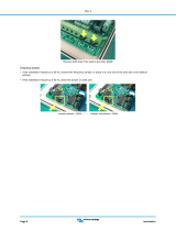
Installation ...........................................................................................4
Conguration Setup ...........................................................................4
EIM, 24VAC Furnace and Lennox Communicating Heat Pumps .... 4
EIM, Lennox Communicating Furnace and 24VAC Heat Pump ...... 4
Unit Type Jumpers ........................................................................... 5
Heat Stage Jumper Positions .......................................................... 5
Air Temperature Sensor Connections .............................................. 6
Lennox Communicating Terminal Connections and Wiring
Recommendations ........................................................................... 6
Dual-Fuel Terminal Connections ..................................................... 6
Conventional Terminal Connections and Wiring Requirement ........ 6
LED Indicators ................................................................................. 7
Soft Disable ..................................................................................... 7
iComfort S30 Commissioning (Conventional Outdoor Unit) ............ 8
Operating Environment Specications ............................................8
Unit Dimensions .................................................................................8
Duel-Fuel Operations .........................................................................9
Field Wiring .......................................................................................10
Alert Codes and Troubleshooting ...................................................16
TABLE OF CONTENTS Shipping and Packing List
Quantity Description
1 Equipment Interface Module.
1 Installation and setup guide
1Warranty certicate
WARNING
Improper installation, adjustment, alteration, ser vice or maintenance can
cause property damage, personal injury or loss of life.
Installation and service must be performed by a li censed professional
HVAC installer (or equivalent) or a service agency.
Application and Requirements
Indoor Transformer Requirements
The following lists the required indoor unit transformer rating (VA) for
specic congurations.
Table 1. System VA Loading Chart
Conguration Minimum Transformer Rating
(VA)
2-Stage HP, 3-Stage Electric heat 70
2-Stage HP, 2-Stage Furnace (with tempering) 70
2-Stage HP, 2-Stage Furnace (without tempering) 50
2-Stage AC, 2-Stage Furnace 40
Equipment
The Equipment Interface Module (EIM) is used with an Lennox
communicating thermostat using the R, i+, i-, and C terminals. The EIM is
the interface between non-communicating HVAC equipment and Lennox
communicating HVAC equipment.
NOTE: EIM will support single-stage outdoor units with single-stage or
variable-stage indoor furnaces.

3
OUTDOOR AIR SENSOR
CONNECTIONS
DISCHARGE AIR
SENSOR CONNECTIONS
ICOMFORT
®
CONNECTIONS
NON-COMMUNICATING TERMINALS
STATUS LED
COMMUNICATION INDICATOR
LED
DUAL-FUEL
CONNECTIONS
UNIT TYPE JUMPER
TERMINALS
HEAT STAGES
JUMPER TERMIINALS HEAT PUMP CAPACITY
JUMPER TERMINALS
3 AMP FUSE
Figure 1. Terminals and LEDs
CAUTION
Electrostatic discharge can aect electronic components. Take precautions during unit installation and service to protect the unit’s electronic controls.
Precautions will help to avoid control exposure to electrostatic discharge by putting the unit, the control and the technician at the same electrostatic
potential. Neutralize electrostatic charge by touching hand and all tools on an unpainted unit surface before performing any service procedure

4
Lennox Communicating
Thermostat
Equipment Interface
Model (EIM)
24VAC Air Handler or
Furnace (Indoor Unit)
iComfort-enabled
Air Conditioner or
Heat Pump
(Outdoor Unit)
Wiring Legend
4−wire communicating
24VAC conventional
EIM with Air Hander or Furnace (Indoor Unit)
and either a Air Conditioner or Heat Pump
(Outdoor Unit)
24VAC Air
Conditioner
or Heat Pump
(Outdoor Unit)
NOTE: For dual-fuel applications, additional components may be need to be added.
Figure 2. System View
WARNING
Controls in this module are sensitive to moisture. Do NOT secure this
module to the sheet metal cabinet where moisture may condense during
periods of high humidity. Secure the module to a nearby wooden stud, if
possible.
Installation
IMPORTANT
The Lennox communicating thermostat paired with the Equipment
Interface Module (EIM) will work with most 24VAC furnaces, air handlers,
air conditioners and heat pumps (up to 2-stages of cooling and 3-stages
of heat).
The Lennox communicating thermostat without the Equipment Interface
Module (EIM) will work with Lennox communicating HVAC equipment.
1. Remove the module cover.
2. Mount the Equipment Interface Module (EIM) near the indoor unit.
3. Use the wiring diagrams reference in the sectoin titled “Field Wiring”
on page 10 to complete the wiring connections for the specic
application and conguration.
Conguration Setup
How the EIM is congured is determined by the system components.
NOTE: Changing jumper positions after the control has been powered-up
requires recommissioning for the change to be recognized.
NOTE: When the Equipment Interface Module is replaced,
recommissioning the Lennox communicating thermostat will also
need to be re-accomplished. See the Lennox communicating
thermostat Setup Guide for recommissioning procedure.
The following examples are two typical congurations used with the EIM.
There are other applications as well and are address in the wiring diagrams
section titled “Field Wiring” on page 10. Those diagrams will indicate all
required jumper settings on the EIM and wiring connections.
EIM, 24VAC Furnace and Lennox Communicating Heat Pumps
See “Figure 12. Dual-Fuel - Conventional Furnace with Lennox
Communicating
Heat Pump (1 or 2-Stage)” on page 11 for wiring details.
1. Set the EIM Unit Type Jumper to IFC.
2. Set the EIM Heat Stage Jumper (see “Table 3. Heat Stage Jumpers”
on page 5) to the applicable number of furnace heat stages or
number of electric heat stages.
3. Use the Lennox communicating thermostat to complete the
commissioning procedure.
EIM, Lennox Communicating Furnace and 24VAC Heat Pump
See “Figure 11. Dual-Fuel - Lennox Communicating Furnace with
Conventional Heat Pump (1 or 2-Stage)” on page 11f or wiring details.
1. Set the EIM Unit Type Jumper to Heat Pump.
2. Set the EIM Heat Stage Jumper (see “Table 3. Heat Stage Jumpers”
on page 5) to the applicable number of heat pump heating stages.
3. Use the Lennox communicating thermostat to complete the
commissioning procedure.

5
NOTE: For two-stage heat pump go to the heat pump defrost control,
locate P3 - low ambient thermostat pins and disable this function
by removing the installed jumper and relocating it to one pin only.
Unit Type Jumpers
Set the unit type jumper for the type of indoor unit being by using the
following table and gure. The factory default setting is IFC. If jumper is
missing from the jumper pins, then alarm 130 is activated.
Table 2. Unit Type Jumpers Positions
Jumper
Position Indoor Unit Outdoor Unit
HP Lennox Communicating
Furnace Conventional Heat Pump
IFC Conventional Furnace Conventional Heat Pump or air
conditioner
AHC Conventional Air Handler
HP IFC AHC
Figure 3. Unit Type Jumper Positions
Heat Stage Jumper Positions
The factory default setting is position 2 (two heat stages). If jumper is
missing from the jumper pins, then alarm 130 is activated. Depending on
the type of equipment and system set up being used:
• Set the number of stages of electric heat (air handler) when jumper pin
selection is AHC selection.
• Set the number of stage of gas heat (Furnace) when jumper pin selection
is IFC.
• Set the number of stages of the compressor when jumper pin selection
is HP.
0 1 2 3
Figure 4. Heat Stage Jumper Positions
Table 3. Heat Stage Jumpers
Label
(Position)
Air Handler Heat
Stages Furnace Heat Stages Heat Pump Stages
Number of
Electric Heat
Stages
Stage
Percentage
Number of
Gas Stages
Stage
Percentage
Number of
Compressors
Stages
Stage
Percentage
0No Electric
Heat 0 1 100% 1 100%
1 1 100% 1 100% 1 100%
2
(default) 250%,
100% 270%.
100% 270%.
100%
3 3
33.5%,
66.5%,
100%
270%,
100% 270%.
100%
NOTE: If jumper is missing, setting defaults to single stage. Changing jumper position
after power-up requires recommission for the change to be recognized.
24VAC Heat Pump Size Setting
Heat pump size must be congured when using a non-communicating
heat pump using the Heat Pump Size jumper (see gure 4 and table 5).
Factory default setting is for 3.0 (3-ton). If jumper is missing from jumper
pins then alarm 130 is activated.
1.
5
2.
0
2.
5
3.
0
3.
5
4.
0
5.
0
Figure 5. Conventional Heap Pump Capacity Jumper Setting

6
Air Temperature Sensor Connections
Refer to “Figure 1. Terminals and LEDs” on page 3 for various
terminal locations.
Table 4. Outdoor Air and Discharge Air Sensors
Label Function / Description
Outdoor Air
Sensor
Show ambient temperatures (optional if weather feed is acceptable or
outdoor unit is a communicating unit; use X2658 Outdoor Sensor - 2
terminals).
NOTE: Wiring distance between the EIM and the outdoor temperature
sensor can not exceed 150 feet (45 meters) when wired with
minimum 22AWG (Recommend) 18AWG dedicated two-
conductor thermostat cable.
Discharge Air
Sensor
Optional for diagnostics of indoor air; use 88K38 Discharge Air Sensor -
2 terminals.
Lennox Communicating Terminal Connections and Wiring
Recommendations
Table 5. Communicating Terminals
Label Function / Description Thermostat Wiring
R 24VAC communication power Input 18AWG unshielded
i+ Communication high – data line 18 - 22AWG shielded
(recommended)
i- Communication low – data line
C24VAC communication common
power Input 18AWG unshielded
IMPORTANT
Use 18AWG unshielded thermostat cable (eld-provided) for power
terminals (R and C) and all non-communicating terminals. Highly
recommend using 18 - 22AWG shielded thermostat cable for
communications terminals ( i+ and i-) which will help eliminate any noise
interference.
Dual-Fuel Terminal Connections
Table 6. Dual-Fuel Terminals
Label Description Function
DFTS
Pre-coil discharge
air temperature (2
terminals)
The pre -coil discharge air sensor should be
installed downstream of the gas heat exchanger
and before the in door coil when a heat pump is
used and defrost tempering is required.
It must be placed in free airow, where other
accessories (such as humidiers, UV lights, etc.)
will not interfere with its accuracy. Wiring distance
between the EIM and the discharge air sensor
should not exceed 10 feet when using 18AWG
thermostat wire.
W1-DEF Defrost signal input
This input is used in systems with non-
communicating heat pumps for defrost indication.
The input provides a nominal load of 50 mA, 24
VAC.
0
Heat Pump Reversing
Valve (Powered for
cooling)
In systems with communicating IFC, the EIM (HP)
O output is connected to a non-communicating
heat pump compatible with O signal for reversing
valve operation. A 24VAC signal is generated on
O for cooling operation, while the terminal is open
for heating operation.
B
Heat Pump Reserving
Valve
(Powered for
heating)
In systems with communicating IFC, the EIM (HP)
B output is connected to a non-communicating
heat pump compatible with B signal for reversing
valve operation. A 24VAC signal is generated on
B for heat pump opera tion, while the terminal is
open for cooling operation.
Conventional Terminal Connections and Wiring Requirement
Table 7. Conventional Terminals
Label Description Function
18AWG unshielded thermostat cable (eld-provided) for
all non-communicating connections
W1 1st - stage heat output (1st stage gas heat output when congured as IFC
and 1st stage electric heat output when congured as AHC.
W2 2nd - stage heat output (2nd stage gas heat output when congured as
IFC and 2nd stage electric heat output when congured as AHC.
W3 3rd - stage heat output (3nd stage electric heat output when congured as
AHC)

7
Table 7. Conventional Terminals
Label Description Function
18AWG unshielded thermostat cable (eld-provided) for
all non-communicating connections
G
Indoor blower control (continuous fan) (monitoring only). G input may be
connected to IAQ devices such as LVCS, HRV or ERV to turn the indoor
blower on and o.
Y2 2nd - stage compressor output
Y1 1st - stage compressor output
DS 24VAC dehumidication signal output. The DS terminal is powered when
there is not a dehumidication call.
CClass II, 24VAC
transformer common
R and C terminals are used to receive power
from the indoor unit and capable of provid ing
the power to the EIM and all the associated
loads. The R power input uses a 3A fuse
(Lennox part number 25J4901.
RClass II. 24VAC
transformer power
H24VAC humidier signal output
OHeat pump reversing
valve (24VAC = cool)
Used as reversing valve output for heat
pumps. The EIM uses a single-pole dual
throw relay to generate O and B signals.
Normally the O output is open and B output
at 24VAC during heating calls. During cooling
calls O is 24VAC and B open. With relay de-
energized 24VAC is present on O terminal.
When power o/ or control reset, 24VAC
power shall not be present on the O
terminal.
BHeat pump reversing
valve (24 VAC = heat)
LED Indicators
This control has two green LED to indicate status and communication
activity One LED is labeled Status and the other is labeled RSBUS.
RSBUS LED
The RSBus LED ashes when information is being communicated over
the RSBus.
Status LED
The following table lists all status LED information.
Table 8. Status LED (Green)
Green LED Function / Description
Steady On Remains steady ON until the device sends its start-up
message.
Blinks 3 second OFF and 1
second ON Soft disable state
Blinks 2 second ON and 2
second OFF
Service is being provided (W, Y or G relay is ON, or G
input ON
Blinks 1 second ON and 1
second OFF
When alarms are present, you may review alarm(s) listed
either on the homeowner notication screen or the menu
/ settings > advanced settings > dealer control center
> notications screen. Information will be listed in either
location on how to clear the alert code(s).
Soft Disable
Soft disabling is when the Lennox communicating thermostat detects
an unknown control such as a indoor or outdoor unit control, iHarmony®
zoning system or Equipment Interface Module (EIM) on the system
communication bus. The thermostat sends the unknown control a
message to go into soft disable mode until component is properly
congured.
The Lennox communicating thermostat will not display any code for a
soft disabled control. When soft disabling occurs only the control that has
been disabled will display the blinking LED status. In this case, the control
blinks three seconds OFF and one second ON.
Use the following procedure if the equipment interface module is
displaying the soft disable code.
1. Conrm proper wiring between all devices such as thermostat, EIM,
indoor and outdoor unit).
2. Cycle power to the control that is displaying the soft disable code.
3. Touch the Lennox icon on the thermostat home screen and hold until
the installer warning screen appears.
4. Touch yes to continue.
5. Touch Setup and then conrm to continue.

8
6. Use this Thermostat? Touch press here to continue.
7. Touch the next button to continue past the next three screens.
8. From the System Devices list, touch reset ALL to reset all devices.
9. Touch the conrm button.
The thermostat will reboot and start through the setup process again.
IMPORTANT
If any jumpers were set incorrectly AFTER commissioning was
completed, then reposition jumpers to correct positions. Re-running the
commissioning procedure will be required at the Lennox communicating
thermostat.
This completes the conguring of the conventional outdoor unit.
iComfort S30 Commissioning (Conventional Outdoor Unit)
Both unit capacity and number of compressor stages are required to be
congured through the Lennox communicating thermostat. Once the
outdoor unit has been installed and connected to the equipment interface
module, go to the thermostat and start the conguration process.
1. From the equipment found screen, touch the non-communication
equipment location to add non-communicating equipment.
2. A add/remove equipment screen will appear. Under Outdoor Unit
Type, select the applicable 1 or 2-stage unit.
3. Touch either the plus or minus buttons to selected the applicable
Outdoor Unit Capacity. Valid options are 18, 24, 30, 36, 42, 48 and
60.
4. Touch save to continue.
Operating Environment Specications
The Equipment Interface Module is designed to operate in the following
environmental conditions.
• Operating Temperature Range: 40°F to 176°F (40° C to 80°C).
• Shipping and Storage Temperature Range: 40° F to 185°F (40°C to
85°C).
• Operating Humidity Range: 10% to 90% non-condensing at 104°F.
Unit Dimensions
8” (203mm)
6” (152mm)
1-5/8” (42mm)
Figure 6. Unit Dimensions

9
Duel-Fuel Operations
To use the EIM in dual-fuel mode, the following equipment combinations
and conguration is required.
Defrost Air Tempering Kit (67M41) will be required. The included DT1
discharge temperature probe is inserted in the furnace air outlet between
the furnace and the indoor coil to keep the furnace from overheating
the coil which would cause heat pump high pressure tripping during the
defrost cycling. The DT1 is only needed with non-communicating furnaces
and is not required for air handlers.
Wiring example for the DT1 Discharge Temperature Probe is in “Figure
13. Dual-Fuel - Conventional Furnace with Conventional Heat Pump
(1 or 2-Stage)” on page 12.
Lennox Communicating
Thermostat
Equipment Interface
Model (EIM)Furnace
24VAC conventional
Heat Pump
(Outdoor Unit)
Outdoor Sensor
(Included with
Heat Pump)
Defrost Tempering
(Available only if
furnace is variable
Optional
capacity
or multi-stage)
Wiring Legend
4-wire communicating
Lennox
Communicating
Non-Communicating
Figure 7. EIM, Conventional Furnace and Lennox Communicating Heat Pump
Wiring Legend 4-wire communicating
24VAC conventional
24VAC
Conventional Heat
Pump
(Outdoor Unit)
X2658 Outdoor
Sensor Required
Equipment Interface
Model (EIM)
Lennox
Communicating
Thermostat
Lennox
Communicating
Furnance
Figure 8. EIM, Conventional Furnace and Conventional Heat Pump

10
Field Wiring
Table 9. Wiring Diagrams
System Type Indoor Unit Outdoor Unit EIM Jumper Settings Diagrams
Unit Type Number and Type of Heat Stages
Air Conditioner Conventional Furnace Conventional Air Conditioner IFC Set to number of furnace stages. Figure 9 on page 11
Air Conditioner Conventional Air Handler Conventional Air Conditioner AHC Set to number of air handler electric heat
stages. Figure 9 on page 11
Heat Pump Conventional Air Handler Conventional Heat Pump HP
Set to number of heat pump compressor
stages.
Figure 10 on page 11
Dual Fuel Conventional Furnace Lennox Communicating Heat
Pump IFC Figure 12 on page 11
Dual Fuel Lennox Communicating
Furnace Conventional Heat Pump HP Figure 11 on page 11
Dual Fuel Conventional Furnace Conventional Heat Pump IFC Figure 13 on page 12
Dual Fuel with
iHarmony
Lennox Communicating
Furnace Conventional Heat Pump HP Figure 16 on page 13
Baseboard Heat Conventional Air Handler* Lennox Communicating Air
Conditioner or Heat Pump IFC
Set to the number of heat pump
compressor stages or air handler electric
heat stages.
Figure 14 on page 12
Hot Water Coil with
Aquastat Blower
Control
Conventional Air Handler* Lennox Communicating Air
Conditioner or Heat Pump IFC Figure 15 on page 12
Accessories -
Dehumidiers,
humidiers, HEPA
Bypass Filter (HRV
/ ERV)
Conventional Air Handler or
Furnace
Conventional Air Conditioner or
Heat Pump IFC Figure 17 on page 14
Accessories - EDA
Humiditrol and
LVCS Ventilation
Control
Conventional Air Handler or
Furnace
Conventional Air Conditioner or
Heat Pump IFC Figure 18 on page 14
* 24VAC conventional air handler or CBX32MV(-6), CBA38MV or CBX40UHV used as 24VAC conventional.

11
REMOVE JUMPER BETWEEN R AND W2
IF PRESENT. IT MAY CAUSE
ERRONEOUS ALERT CODE 125.
ICOMFORT SERIES
THERMOSTAT
Y2
Out
BL
Figure 9. Conventional Furnace or Air Hander with Conventional Air Conditioner
(1 or 2-Stage)
REMOVE JUMPER BETWEEN R AND W2
IF PRESENT. IT MAY CAUSE
ERRONEOUS ALERT CODE 125.
ICOMFORT SERIES
THERMOSTAT
Y2 OUT
BL
Figure 10. Conventional Air Hander with Conventional Heat Pump (1 or 2-Stage)
ICOMFORT SERIES
THERMOSTAT
Y2
Y2 OUT
BL
Y2 OUT IS FOR TWO-STAGE UNITS
ONLY (XP16 & XP19)
Figure 11. Dual-Fuel - Lennox Communicating Furnace with Conventional Heat
Pump (1 or 2-Stage)
IF THERE IS A JUMPER INSTALLED
BETWEEN R AND W2 ON INDOOR UNIT,
THEN REMOVED. IF NOT REMOVE IT
MAY CAUSE ERRONEOUS ALERT
CODE 125.
REMOVE JUMPER BETWEEN R AND W2 IF
PRESENT. IT MAY CAUSE ERRONEOUS ALERT
CODE 125.
ICOMFORT SERIES
THERMOSTAT
Y2 OUT
BL
NOTE: NOT APPLICABLE FOR VARIABLE CAPACITY OUTDOOR UNITS.
Figure 12. Dual-Fuel - Conventional Furnace with Lennox Communicating
Heat Pump (1 or 2-Stage)

12
REMOVE JUMPER BETWEEN R AND W2
IF PRESENT. IT MAY CAUSE
ERRONEOUS ALERT CODE 125.
ICOMFORT SERIES
THERMOSTAT
Y2 OUT
BL
Figure 13. Dual-Fuel - Conventional Furnace with Conventional Heat Pump
(1 or 2-Stage)
ICOMFORT SERIES
THERMOSTAT
Y2 OUT
BL
Figure 14. Baseboard Heat - Conventional Air Handler (CBX32MV(-6) or
CBX40UHV) with either a Lennox Communicating Air Conditioner or Heat Pump
Figure 15. Hot Water Coil Heat with Aquastat Blower Control - Conventional Air
Handler (CBX32MV(-6) or CBX40UHV)

13
ICOMFORT SERIES
THERMOSTAT
Y2 OUT
BL
3
2
Figure 16. Dual-Fuel - Lennox Communicating Furnace, iHarmony Zoning and Conventional Heat Pump

14
REMOVE JUMPER
BETWEEN R AND
W2 IF PRESENT.
IT MAY CAUSE
ERRONEOUS ALERT
CODE 125.
ICOMFORT SERIES
THERMOSTAT
Figure 17. Optional Accessories with Conventional Indoor Unit (HEPA Bypass Filter,
ERV/HRV, 24VAC Humidier and HCWHD3 Humidier)
REMOVE JUMPER BETWEEN R AND W2
IF PRESENT. IT MAY CAUSE
ERRONEOUS ALERT CODE 125.
ICOMFORT SERIES
THERMOSTAT
Y2 OUT
BL
Y2 OUT
BL
Figure 18. Conventional Indoor and Outdoor Units (EDA Humiditrol and LVCS
Ventilation Control System)

15
Alert Codes and Troubleshooting
Error codes are transmitted to the thermostat. No codes are stored in the EIM.
Table 10. Alert Codes and Troubleshooting
Alert Code Priority
Condition
Applicable System
Component(s)
Alert Text Component or System Operational State
and Troubleshooting Tip How to clear the alert code
10 Critical
All Lennox Communicating
thermostats.
Communicating air handler,
furnace, outdoor unit, EIM
and iHarmony.
The thermostat has
found an unknown
device on the
system.
Lennox communicating thermostat when NOT in con guration mode
has detected an unknown device. Typically the thermostat will send
a command to the unknown device and place it in a soft disable
state.
The soft disable control will indicate as follows:
√ On air handler, furnace and outdoor controls, the state is displayed
by double horizontal lines on sev en-segment display.
√ On the damper control module or equipment inter face equipment,
the green LED will blink three sec onds on and one second o.
Cycling power to the soft disabled control may clear the condition.
If cycling power does not clear the soft disabled state then replace
control.
Clear alert code by
reconguring the system
12 Critical
All Lennox Communicating
thermostats.
Lennox Communicating
furnace, EIM or air handler
The thermostat
cannot nd a Lennox
communicating indoor
unit
Lennox communicating thermostat did not nd an indoor unit. Make
sure there is an Lennox communicating indoor unit on the system.
√ Check R, i+, i- and C connections and voltages.
√ Ohm wires and cycle power.
√ Check for voltage and missing component.
√ Verify that equipment interface module is congured as air handler
or furnace when used with a non-com municating indoor unit.
√ Go to menu > advanced settings > view dealer control center
> equipment and press reset all equipment. This will allow the
system to auto-detect any Lennox communicating components
attached.
√ Replace indoor unit control if there is no response.
Automatically clears when
the system detects that the
issue no longer exists.
105 Critical
All Lennox Communicating
thermostats.
Lennox Communicating
furnace, air handler, outdoor
unit, EIM or iHarmony
A system component
has lost communication
with the system.
System component (device) is unable to communi cate.
√ This may indicate the existence of other active alert codes.
√ In most cases errors are related to electrical noise. Verify that high
voltage power is separated from the low voltage communication
wires.
√ Check for incorrectly wired or loose connections be tween system
components (devices).
√ Check for a high voltage source of noise close to the system.
Automatically clears when
the system detects the
issue no longer exists.

16
Table 10. Alert Codes and Troubleshooting
Alert Code Priority
Condition
Applicable System
Component(s)
Alert Text Component or System Operational State
and Troubleshooting Tip How to clear the alert code
114 Moderate /
Critical
Lennox Communicating
Furnace, air handler, EIM or
IHarmony
There is a frequency /
distortion problem with
the power to a specic
system component.
√ This alert code may indicate transformer overload ing.
√ Check the voltage and line power frequency.
√ Check the generator operating frequency, if the system is running
on back-up power.
√ Correct voltage and frequency problems.
√ System will resume normal operation ve seconds after fault
recovered.
√ All applicable system component outputs are dis abled – moderate
condition.
√ After 10 minutes, the priority condition is escalated – critical
condition.
√ Damper control module will operate in central mode only until proper
voltage is restored or frequency dis tortion is resolved – moderate
condition.
Automatically clears when
the system detects the
issue no longer exists.
115 Critical Lennox Communicating
Furnace, air handler or EIM
Primary 24VAC power
to a system compo nent
control is lower than
the required range of
18 to 30VAC.
√ Check and correct voltage.
√ Check for additional power-robbing system compo nents (devices)
connected to system.
√ This alert code may require the installation of an ad ditional or larger
VA transformer.
Automatically clears when
the system detects the
issue no longer exists.
120 Moderate
All Lennox Communicating
thermostats.
Lennox communicating
furnace, air handler, outdoor
unit, EIM or iHarmony
There is a delay in the
system component
responding to the
system.
Typically this alert code does not cause any opera tional issues and
will clear on its own.
√ This alert code is usually caused by a delay in the outdoor unit
responding to the thermostat.
√ Check all wiring connections.
Automatically clears after
an unresponsive system
compo nent (device)
responds to any in quiry.
124 Critical
All Lennox Communicating
thermostats.
Lennox communicating
furnace, air handler, outdoor
unit, EIM or iHarmony
The thermostat has lost
communication with
a system compo nent
for more than three
minutes.
System component has lost communication with the thermostat.
√ Check the wiring connections.
√ Ohm wires.
√ Cycle power.
√ Check voltage at component.
This alert code stops all associated system operations and waits
for a heartbeat message from the system component that is not
communicating.
Automatically clears after
com munication is re-
established with applicable
system component (de-
vice).
125 Critical
All Lennox Communicating
thermostats.
Lennox communicating
furnace, air handler, outdoor
unit, EIM or iHarmony
There is a hardware
problem on a system
component control.
There is a control hardware problem.
√ Replace the control if the problem prevents opera tion and is
persistent.
√ Damper control module will remain in non-zone mode (all dampers
open) for ve minutes after priori ty condition no longer exist.
√ Remove jumper if present on indoor unit between R and W2 if
equipment interface module is in use.
Automatically clears 300
sec onds after the is sue no
longer ex ists.

17
Table 10. Alert Codes and Troubleshooting
Alert Code Priority
Condition
Applicable System
Component(s)
Alert Text Component or System Operational State
and Troubleshooting Tip How to clear the alert code
130 Moderate EIM Air handler jumper is
missing.
√ Conguration jumper missing on equipment inter face module.
√ Install the missing jumper.
NOTE: This is applicable in non-communicating appli cations only).
Automatically clears after
the missing or incor rectly
installed jumper is installed
or corrected.
131 Critical
All Lennox Communicating
thermostats.
Lennox communicating
furnace, air handler, outdoor
unit, EIM or iHarmony
System component
control parameters are
corrupted.
√ Replace the system component control if heating or cooling is not
available.
√ Try resetting the thermostat.
Will automatically clear
when sys tem component
(device) passes memory
self-test or system
component control is re
placed.
132 Critical Lennox communicating Air
handler, EIM or iHarmony
System component
control software is cor-
rupted
√ Recycle power.
√ If failure re-occurs, replace the system component control.
Manual system power reset
is re quired to recover from
this alert code.
180 Critical Lennox communicating
Furnace, air handler or EIM
The thermostat has
found a problem with
a system component’s
outdoor temperature
sensor.
In normal operation after system component control recognizes
sensors, the alarm will be sent if valid tem perature reading is lost.
√ Compare outdoor sensor resistance to temperature / resistance
charts in unit installation instructions.
√ Replace sensor pack if necessary.
√ At the beginning of (any) conguration, furnace, air- handler control
or equipment interface module will detect the presence of the
sensor(s).
√ If detected (reading in range), appropriate feature will be set as
‘installed’ and shown in the ‘About’ screen.
Automatically clears upon
con guration, or sensing
normal values.
310 Moderate
Lennox communicating
Furnace, air handler, EIM or
iHarmony
There is a discharge
air temperature sensor
issue.
Compare discharge temperature sensor resistance to temperature /
resistance charts in system component installation instruction.
√ Replace discharge air sensor if failed.
√ If applicable, iHarmony will operate in non-zone mode (all dampers
open).
NOTE: Conrm there is no short or open circuits in the Lennox
communicating thermostat connections to any of the other
components in the communication system.
Automatically clears 30
seconds after condi tion is
detected as recovered or
after system restart.
345 Critical Lennox communicating Air
handler, EIM or heat pump
The O relay on the
system component has
failed. Either the pilot
relay contacts did not
close or the relay coil
did not energize.
Possible O relay / stage 1 failure.
√ Pilot relay contacts did not close or the relay coil did not energize.
√ Replace system component (device) control.
√ If error is applicable to the XC/XP 25, the outdoor control will need
to be replaced.
Automatically clears
after the fault recovered
following reset.

18
Table 10. Alert Codes and Troubleshooting
Alert Code Priority
Condition
Applicable System
Component(s)
Alert Text Component or System Operational State
and Troubleshooting Tip How to clear the alert code
347 Critical Lennox communicating
Furnace, air handler or EIM
The Y1 relay on the
applicable system
component has failed.
Either the pilot relay
contacts did not close
or the relay coil did not
energize.
√ System operation will stop.
√ Possible Y1 relay / stage 1 failure.
√ Pilot relay contacts did not close or the relay coil did not energize.
√ There is no input back to the applicable system component control.
Automatically clears
after reset and Y1 input
sensed.
380 Moderate /
Critical EIM
Interlock relay failure
(IFC or AHC mode
on ly).
√ Interlock relay is energized, but input is not sensed after three
seconds.
√ There will be no heating or cooling due to this alert code – moderate
condition.
√ De-energize interlock relay and energize after ve minutes if
demand is still present – critical condi tion.
Automatically clears after
fault recovered.
381 Moderate /
Critical EIM
Interlock relay stuck
(IFC or AHC modes
only)
√ Interlock relay continuously sensed (with relay o).
√ There is no heating and cooling operation – moderate condition.
√ After 10 minutes if event still exist it will be escalated – critical
condition.
Automatically clears 30
seconds after fault clears
382 Moderate EIM
Relay W1 failure
(IFC and AHC modes
only)
W1 relay is energized but input is not sensed after three seconds. Automatically clears when
W1 relay input is sensed.
418 Moderate EIM and Lennox
communicating outdoor unit
There is a faulty W
output circuit.
√ W terminal is energized while in cooling mode.
√ Possible cause may be a stuck closed relay on the control, or
something external to the control that is energizing W terminal when
it should not be ener gized.
√ Disconnect any wiring from the W terminal.
√ If 24VAC is still on the terminal, then it is a stuck relay.
√ If 24VAC disappears, then there is a need to check any of the wires
hooked up to the W terminal.
Automatically clears after
fault signal is re moved.
419 Critical EIM and Lennox
communicating outdoor unit
The W output has re
ported more than ve
errors
√ The system will shut down the outdoor unit.
√ The W output (alert code 418) on the outdoor unit has reported more
than ve strikes.
√ Disconnect thermostat wire from W and verify there is no 24VAC on
the W.
√ If 24VAC is present, replace the outdoor control.
Automatically clears after
power recycled.
420 Critical Lennox communicating Air
handler or EIM
The heat pump defrost
cycle has taken more
than 20 minutes to
complete
√ Defrost cycle lasts longer than 20 minutes.
√ Check heat pump operation.
√ This is applicable only in communicating indoor unit with non-
communicating heat pump.
Automatically clears when
W1 signal is re moved.

19
Table 10. Alert Codes and Troubleshooting
Alert Code Priority
Condition
Applicable System
Component(s)
Alert Text Component or System Operational State
and Troubleshooting Tip How to clear the alert code
421 Critical EIM and Lennox
communicating outdoor unit
The W output terminal
on the outdoor unit is
not wired correctly.
Voltage sensed on W output terminal when Y1 out is deactivated.
Automatically clears once
volt age is not sense on
output for pow er cycled.
594 Moderate /
Critical EIM
Pre-coil discharge air
temperature sensor
problem (DFM mode
only). Advances
from moderate to
critical after ten (10)
minutes.
√ Interlock relay energized, but input not sensed after three seconds.
√ No heating and cooling operations.
√ De-energize interlock relay and re-energized ve minutes later if
demand is still present.
Alarm clears ve minutes
after fault clears.

20
/