Sharp R-408LS Owner's manual

Category
Microwaves
Type
Owner's manual

This manual is also suitable for

PRECAUTIONS TO BE OBSERVED BEFORE AND
DURING SERVICING TO AVOID POSSIBLE EXPO-
SURE TO EXCESSIVE MICROWAVE ENERGY
BEFORE SERVICING
CHAPTER 1. WARNING TO SERVICE PERSONNEL
CHAPTER 2. MICROWAVE MEASUREMENT PRO-
CEDURE
CHAPTER 3. FOREWORD AND WARNING
CHAPTER 4. PRODUCT DESCRIPTION
CHAPTER 5. GENERAL INFORMATION
CHAPTER 6. OPERATION
CHAPTER 7. TROUBLESHOOTING GUIDE
CHAPTER 8. TEST PROCEDURES
CHAPTER 9. TOUCH CONTROL PANEL ASSEMBLY
CHAPTER 10. PRECAUTIONS FOR USING LEAD-
FREE SOLDER
CHAPTER 11. COMPONENT REPLACEMENT AND
ADJUSTMENT PROCEDURE
CHAPTER 12. CIRCUIT DIAGRAMS
Parts List
SY612R408LPSTF
SERVICE MANUAL
R408LS
CONTENTS
This document has been published to be used for
after sales service only.
The contents are subject to change without notice.
TopPage
MICROWAVE OVEN
R-408LS
MODEL
In the interest of user-safety the oven should be restored to its origi-
nal condition and only parts identical to those specified should be
used.
WARNING TO SERVICE PERSONNEL: Microwave ovens con-
tain circuitry capable of producing very high voltage and cur-
rent, contact with following parts may result in a severe,
possibly fatal, electrical shock. (High Voltage Capacitor, High
Voltage Power Transformer, Magnetron, High Voltage Rectifier
Assembly, High Voltage Harness etc..)
CONTENTS
PRECAUTIONS TO BE OBSERVED BEFORE
AND DURING SERVICING TO AVOID POSSIBLE
EXPOSURE TO EXCESSIVE MICROWAVE ENER-
GY
BEFORE SERVICING
CHAPTER 1. WARNING TO SERVICE PERSON-
NEL
[1] Before Servicing.......................................... 1-1
[2] When the testing is completed,................... 1-1
[3] After repairing.............................................. 1-1
CHAPTER 2. MICROWAVE MEASUREMENT
PROCEDURE
[1] Requirements:............................................. 2-1
[2] Preparation for testing:................................ 2-1
[3] Leakage test: .............................................. 2-1
CHAPTER 3. FOREWORD AND WARNING
[1] FOREWORD............................................... 3-1
[2] WARNING................................................... 3-1
[3] DANGER..................................................... 3-1
CHAPTER 4. PRODUCT DESCRIPTION
[1] SPECIFICATIONS ...................................... 4-1
CHAPTER 5. GENERAL INFORMATION
[1] GROUNDING INSTRUCTIONS.................. 5-1
[2] OVEN DIAGRAM ........................................ 5-1
CHAPTER 6. OPERATION
[1] DESCRIPTION OF OPERATING SE-
QUENCE .................................................... 6-1
[2] OVEN SCHEMATIC .................................... 6-2
[3] DESCRIPTION AND FUNCTION OF
COMPONENTS .......................................... 6-3
CHAPTER 7. TROUBLESHOOTING GUIDE
[1] TROUBLESHOOTING CHART ................. 7-1
CHAPTER 8. TEST PROCEDURES
[1] A: MAGNETRON ASSEMBLY TEST .......... 8-1
[2] B: POWER TRANSFORMER TEST ........... 8-1
[3] C: HIGH VOLTAGE RECTIFIER TEST....... 8-1
[4] D: HIGH VOLTAGE CAPACITOR TEST..... 8-2
[5] E: TEMPERATURE FUSE OR THER-
MAL CUT-OUT TEST ................................. 8-2
[6] F: PRIMARY INTERLOCK SWITCH
TEST........................................................... 8-2
[7] F: SECONDARY INTERLOCK SYSTEM
TEST........................................................... 8-3
[8] G: MONITOR SWITCH TEST ..................... 8-3
[9] H: BLOWN MONITOR FUSE TEST ........... 8-4
[10] I: NOISE FILTER TEST .............................. 8-4
[11] J: TOUCH CONTROL PANEL ASSEM-
BLY TEST ................................................... 8-4
[12] K: KEY UNIT TEST..................................... 8-5
[13] L: RELAY TEST .......................................... 8-5
[14] M: DEFROST TEST.................................... 8-6
[15] N: FOIL PATTERN ON THE PRINTED
WIRING BOARD TEST............................... 8-6
CHAPTER 9. TOUCH CONTROL PANEL ASSEM-
BLY
[1] OUTLINE OF TOUCH CONTROL PAN-
EL ............................................................... 9-1
[2] SERVICING FOR TOUCH CONTROL
PANEL ........................................................ 9-1
CHAPTER 10. PRECAUTIONS FOR USING LEAD-
FREE SOLDER
[1] Employing lead-free solder ....................... 10-1
[2] Using lead-free wire solder ....................... 10-1
[3] Soldering................................................... 10-1
CHAPTER 11. COMPONENT REPLACEMENT
AND ADJUSTMENT PROCEDURE
[1] WARNINGS ...............................................11-1
[2] OUTER CASE REMOVAL .........................11-2
[3] POWER TRANSFORMER REMOVAL ......11-2
[4] HIGH VOLTAGE RECTIFIER AND HIGH
VOLTAGE CAPACITOR REMOVAL...........11-2
[5] MAGNETRON REMOVAL .........................11-2
[6] OVEN LAMP REMOVAL............................11-3
[7] POSITIVE LOCK CONNECTOR (NO-
CASE TYPE) REMOVAL ...........................11-3
[8] TURNTABLE MOTOR REMOVAL .............11-3
[9] COOLING FAN MOTOR REMOVAL..........11-3
[10] CONTROL PANEL ASSEMBLY RE-
MOVAL.......................................................11-4
[11] GRAPHIC SHEET AND MEMBRANE
SWITCH REPLACEMENT.........................11-4
[12] DOOR SENSING SWITCH/PRIMARY
INTERLOCK SWITCH AND MONITOR
SWITCH REMOVAL...................................11-5
[13] DOOR SENSING SWITCH/PRIMARY
INTERLOCK SWITCH AND MONITOR
SWITCH ADJUSTMENT............................11-5
[14] DOOR REPLACEMENT ............................11-5
CHAPTER 12. CIRCUIT DIAGRAMS
[1] Pictorial Diagram (Figure S-1) .................. 12-1
[2] Control Panel Circuit (Figure S-2)............. 12-2
[3] Printed Wiring Board (Figure S-3)............. 12-3
Parts List
R408LS
i
R408LS Service Manual
PRECAUTIONS TO BE OBSERVED BEFORE AND DURING SERVICING TO AVOID
POSSIBLE EXPOSURE TO EXCESSIVE MICROWAVE ENERGY
BEFORE SERVICING
PRECAUTIONS TO BE OBSERVED BEFORE AND
DURING SERVICING TO AVOID POSSIBLE
EXPOSURE TO EXCESSIVE MICROWAVE
ENERGY
(a) Do not operate or allow the oven to be operated with the door open.
(b) Make the following safety checks on all ovens to be serviced before activating the magnetron or other
microwave source, and make repairs as necessary: (1) interlock operation, (2) proper door closing, (3)
seal and sealing surfaces (arcing, wear, and other damage), (4) damage to or loosening of hinges and
latches, (5) evidence of dropping or abuse.
(c) Before turning on microwave power for any service test or inspection within the microwave generating
compartments, check the magnetron, wave guide or transmission line, and cavity for proper alignment,
integrity, and connections.
(d) Any defective or misadjusted components in the interlock, monitor, door seal, and microwave
generation and transmission systems shall be repaired, replaced, or adjusted by procedures described
in this manual before the oven is released to the owner.
(e) A microwave leakage check to verify compliance with the Federal Performance Standard should be
performed on each oven prior to release to the owner.
BEFORE SERVICING
Before servicing an operative unit, perform a microwave emission check as per the Microwave
Measurement Procedure outlined in this service manual.
If microwave emissions level is in excess of the specified limit, contact SHARP ELECTRONICS
CORPORATION immediately @1-800-237-4277.
If the unit operates with the door open, service person should 1) tell the user not to operate the oven
and 2) contact SHARP ELECTRONICS CORPORATION and Food and Drug Administration's
Center for Devices and Radiological Health immediately.
Service personnel should inform SHARP ELECTRONICS CORPORATION of any certified unit found
with emissions in excess of 4mW/cm . The owner of the unit should be instructed not to use the unit
until the oven has been brought into compliance.
2
R408LS
1 – 1
R408LS Service Manual
CHAPTER 1. WARNING TO SERVICE PERSONNEL
Microwave ovens contain circuitry capable of producing very high voltage and current, contact with following parts may result in a severe, possibly
fatal, electrical shock.
(Example)
High Voltage Capacitor, High Voltage Power Transformer, Magnetron, High Voltage Rectifier Assembly, High Voltage Harness etc..
Read the Service Manual carefully and follow all instructions.
[1] Before Servicing
1. Disconnect the power supply cord , and then remove outer
case.
2. Open the door and block it open.
3. Discharge high voltage capacitor.
WARNING: RISK OF ELECTRIC SHOCK. DISCHARGE THE HIGH-
VOLTAGE CAPACITOR BEFORE SERVICING.
The high-voltage capacitor remains charged about 60 seconds
after the oven has been switched off. Wait for 60 seconds and
then short-circuit the connection of the high-voltage capacitor
(that is the connecting lead of the high-voltage rectifier) against
the chassis with the use of an insulated screwdriver.
Whenever troubleshooting is performed the power supply must be dis-
connected. It may, in some cases, be necessary to connect the power
supply after the outer case has been removed, in this event,
1) Disconnect the power supply cord, and then remove outer case.
2) Open the door and block it open.
3) Discharge high voltage capacitor.
4) Disconnect the leads to the primary of the power transformer.
5) Ensure that the leads remain isolated from other components and
oven chassis by using insulation tape.
6) After that procedure, reconnect the power supply cord.
[2] When the testing is completed,
1. Disconnect the power supply cord, and then remove outer case.
2. Open the door and block it open.
3. Discharge high voltage capacitor.
4. Reconnect the leads to the primary of the power transformer.
5. Reinstall the outer case (cabinet).
6. Reconnect the power supply cord after the outer case is installed.
7. Run the oven and check all functions.
[3] After repairing
1. Reconnect all leads removed from components during testing.
2. Reinstall the outer case (cabinet).
3. Reconnect the power supply cord after the outer case is installed.
4. Run the oven and check all functions.
Microwave ovens should not be run empty. To test for the presence of
microwave energy within a cavity, place a cup of cold water on the
oven turntable, close the door and set the power to HIGH and set the
microwave timer for two (2) minutes. When the two minutes has
elapsed (timer at zero) carefully check that the water is now hot. If the
water remains cold carry out Before Servicing procedure and re-
examine the connections to the component being tested.
When all service work is completed and the oven is fully assembled,
the microwave power output should be checked and microwave leak-
age test should be carried out.
Don't Touch !
Danger High Voltage
R408LS
2 – 1
R408LS Service Manual
CHAPTER 2. MICROWAVE MEASUREMENT PROCEDURE
[1] Requirements:
1. Microwave leakage limit (Power density limit): The power density of microwave radiation emitted by a microwave oven should not exceed 1mW/
cm2 at any point 5cm or more from the external surface of the oven, measured prior to acquisition by a purchaser, and thereafter (through the use-
ful life of the oven), 5 mW/cm2 at any point 5cm or more from the external surface of the oven.
2. Safety interlock switches:
Primary interlock switch shall prevent microwave radiation emission in excess of the requirement as above mentioned. Secondary interlock relay
and door sensing switch shall prevent microwave radiation emission in excess of 5 mW/cm2 at any point 5cm or more from the external surface of
the oven.
[2] Preparation for testing:
Before beginning the actual measurement of leakage, proceed as follows:
1. Make sure that the actual instrument is operating normally as specified in its instruction booklet.
Important:
Survey instruments that comply with the requirement for instrumentation as prescribed by the performance standard for microwave ovens, 21 CFR
1030.10(c)(3)(i), must be used for testing.
2. Place the oven tray in the oven cavity.
3. Place the load of 275±5 ml (9.8 oz) of tap water initially at 20±5°C (68°F) in the center of the oven cavity.
The water container shall be a low form of 600 ml (20 oz) beaker with an inside diameter of approx. 8.5 cm (3-1/2 in.) and made of an electrically
nonconductive material such as glass or plastic.
The placing of this standard load in the oven is important not only to protect the oven, but also to insure that any leakage is measured accurately.
4. Set the cooking control on Full Power Cooking Mode
5. Close the door and select a cook cycle of several minutes. If the water begins to boil before the survey is completed, replace it with 275 ml of cool
water.
[3] Leakage test:
Closed-door leakage test (microwave measurement)
1. Grasp the probe of the survey instrument and hold it perpendicular to the gap between the door and the body of the oven.
2. Move the probe slowly, not faster than 1 in./sec. (2.5 cm/sec.) along the gap, watching for the maximum indication on the meter.
3. Check for leakage at the door screen, sheet metal seams and other accessible positions where the continuity of the metal has been breached (eg.,
around the switches, indicator, and vents).
While testing for leakage around the door pull the door away from the front of the oven as far as is permitted by the closed latch assembly.
4. Measure carefully at the point of highest leakage and make sure that the highest leakage is no greater than 4mW/cm2, and that the secondary
interlock relay and the primary interlock switch do turn the oven OFF before any door movement.
NOTE: After servicing, record data on service invoice and microwave leakage report.
R408LS
3 – 1
R408LS Service Manual
CHAPTER 3. FOREWORD AND WARNING
[1] FOREWORD
This Manual has been prepared to provide Sharp Electronics Corp. Service Personnel with Operation and Service Information for the SHARP
MICROWAVE OVEN, R-408LS.
It is recommended that service personnel carefully study the entire text of this manual so that they will be qualified to render satisfactory customer
service.
Check the interlock switches and the door seal carefully. Special attention should be given to avoid electrical shock and microwave radiation hazard.
[2] WARNING
Never operate the oven until the following points are ensured.
(A) The door is tightly closed.
(B) The door brackets and hinges are not defective.
(C) The door packing is not damaged.
(D) The door is not deformed or warped.
(E) There is no other visible damage with the oven.
Servicing and repair work must be carried out only by trained service personnel.
[3] DANGER
Certain initial parts are intentionally not grounded and present a risk of electrical shock only during servicing. Service personnel - Do not contact the
following parts while the appliance is energized;
High Voltage Capacitor, Power Transformer, Magnetron, High Voltage Rectifier Assembly, High Voltage Harness;
If provided, Vent Hood, Fan assembly, Cooling Fan Motor.
All the parts marked “ “ on parts list are used at voltages more than 250V.
Removal of the outer wrap gives access to voltage above 250V.
All the parts marked “*“on parts list may cause undue microwave exposure, by themselves, or when they are damaged, loosened or removed.
R408LS
4 – 1
R408LS Service Manual
CHAPTER 4. PRODUCT DESCRIPTION
[1] SPECIFICATIONS
ITEM DESCRIPTION
Power Requirements
120 Volts
60 Hertz
Single phase, 3 wire grounded
Power Consumption 1600W / Approx. 13.5 Amperes
Power Output 1100 W nominal of RF microwave energy (IEC Test procedure)
Operating frequency 2450 MHz
Outside Dimensions
Width 21-5/8"
Height 12-3/8"
Depth 17-1/2"
Cooking Cavity Dimensions
(1.4 Cubic feet)
Width 15-3/8" NOTE: Internal capacity is calculated by measuring
Height 9-3/8" maximum width, depth and height.
Depth 16-3/4" Actual capacity for holding food is less.
Control Complement
Touch Control System
Clock (1:00 - 12:59)
Timer (0 - 99 minutes 99 seconds)
Microwave Power for Variable Cooking
Repetition Rate;
P-HI -------------------- Full power throughout the cooking time
P-90 -------------------- approx. 90% of FULL Power
P-80 -------------------- approx. 80% of FULL Power
P-70 -------------------- approx. 70% of FULL Power
P-60 -------------------- approx. 60% of FULL Power
P-50 -------------------- approx. 50% of FULL Power
P-40 -------------------- approx. 30% of FULL Power
P-30 -------------------- approx. 40% of FULL Power
P-20 -------------------- approx. 20% of FULL Power
P-10 -------------------- approx. 10% of FULL Power
P-0 ---------------------- No power throughout the cooking time
POPCORN pad
MINUTE PLUS pad
Cook pad
Defrost pad
Reheat pad
Number selection pads
Power Level pad
Timer/Clock pad
Stop/Clear pad
START pad
Melt, Soften, Warm pads
Oven Cavity Light Yes
Safety Standard UL listed FCC Authorized
DHHS Rules, CFR, Title 21, Chapter 1, Subchapter J
R408LS
5 – 1
R408LS Service Manual
CHAPTER 5. GENERAL INFORMATION
[1] GROUNDING INSTRUCTIONS
This oven is equipped with a three prong grounding plug. It must be plugged into a wall receptacle that is properly installed and grounded in accor-
dance with the National Electrical Code and local codes and ordinances.
In the event of an electrical short circuit, grounding reduces the risk of electric shock by providing an escape wire for the electric current.
WARNING: Improper use of the grounding plug can result in a risk of electric shock.
Electrical Requirements
The electrical requirements are a 120 volt 60 Hz, AC only, 15 or 20 amp. fused electrical supply. It
is recommended that a separate circuit serving only this appliance be provided. When installing
this appliance, observe all applicable codes and ordinances. A short power-supply cord is provided
to reduce risks of becoming entangled in or tripping over a longer cord. Where a two-pronged wall-
receptacle is encountered, it is the personal responsibility and obligation of the customer to contact
a qualified electrician and have it replaced with a properly grounded three-pronged wall receptacle
or have a grounding adapter properly grounded and polarized. If the extension cord must be used,
it should be a 3-wire, 15 amp. or higher rated cord. Do not drape over a countertop or table where
it can be pulled on by children or tripped over accidentally.
CAUTION: DO NOT UNDER ANY CIRCUMSTANCES CUT OR REMOVE THE ROUND
GROUNDING PRONG FROM THIS PLUG.
[2] OVEN DIAGRAM
1. OVEN
1. One touch door open button.
Push to open door.
2. Door latches.
The oven will not operate unless
the door is securely closed.
3. Removable turntable support
4. Removable turntable.
The turntable will rotate clockwise
or counterclockwise.
5. Oven lamp.
It will light when oven is operating
or door is opened.
6. Oven door with see-through win-
dow
7. Ventilation openings. (Rear)
8. Auto-Touch control panel.
9. Time display: Digital display, 99 minutes, 99 seconds.
10.Waveguide cover:
11. Power supply cord.
3-Pronged
Plug
Grounded
Receptacle Box
Grounding Pin
3-Pronged Receptacle
1
65
210
11
9
7
8
3
4
R408LS
5 – 2
2. TOUCH CONTROL PANEL
NOTE: Some one-touch cooking features such as “MINUTE PLUS” are disabled after three minutes when the oven is not in use. These fea-
tures are automatically enabled when the door is opened and closed or the STOP/ CLEAR pad is pressed.
R408LS
6 – 1
R408LS Service Manual
CHAPTER 6. OPERATION
[1] DESCRIPTION OF OPERATING SEQUENCE
The following is a description of component functions during oven operation.
1. OFF CONDITION
Closing the door activates the door sensing switch and primary inter-
lock switch. (In this condition, the monitor switch contacts are opened.)
When oven is plugged in, 120 volts A.C. is supplied to the control unit.
(Figure O-1).
1) The display will show flashing “88:88”.
To set any program or set the clock, you must first touch the STOP/
CLEAR pad. The display will clear, and " : " will appear.
2. COOKING CONDITION
Program desired cooking time by touching the NUMBER pads. Pro-
gram the power level by touching the POWERLEVEL pad and then a
Number pad. When the START pad is touched, the following opera-
tions occur:
1) The contacts of relays are closed and components connected to
the relays are turned on as follows.
(For details, refer to Figure O-2)
2) 120 volts A.C. is supplied to the primary winding of the power trans-
former and is converted to about 3.3 volts A.C. output on the fila-
ment winding, and approximately 2370 volts A.C. on the high
voltage winding.
3) The filament winding voltage heats the magnetron filament and the
H.V. winding voltage is sent to a voltage doubler circuit.
4) The microwave energy produced by the magnetron is channelled
through the waveguide into the cavity feed-box, and then into the
cavity where the food is placed to be cooked.
5) Upon completion of the cooking time, the power transformer, oven
lamp, etc. are turned off, and the generation of microwave energy
is stopped. The oven will revert to the OFF condition.
6) When the door is opened during a cook cycle, the monitor switch,
door sensing switch, primary interlock switch, relay (RY1) and sec-
ondary interlock relay are activated with the following results. The
circuits to the turntable motor, the cooling fan motor, and the high
voltage components are de-energized, the oven lamp remains on,
and the digital read-out displays the time still remaining in the cook
cycle when the door was opened.
7) The monitor switch electrically monitors the operation of the pri-
mary interlock switch and secondary interlock relay and is mechan-
ically associated with the door so that it will function in the following
sequence.
a) When the door opens from the closed position, the secondary
interlock relay (RY2) and primary interlock switch open their
contacts. And contacts of the relay (RY1) remains closed. Then
the monitor switch contacts close.
b) When the door is closed from the open position, the monitor
switch contacts open first. Then the contacts of the primary
interlock switch and door sensing switch close. And contacts of
the relay (RY1) open.
If the primary interlock switch and secondary interlock relay (RY2) fail
with the contacts closed when the door is opened, the closing of the
monitor switch contacts will form a short circuit through the monitor
fuse, primary interlock switch, relay (RY1) and secondary interlock
relay (RY2), causing the monitor fuse to blow.
3. POWER LEVEL P-0 TO P-90 COOKING
When Variable Cooking Power is programmed, the 120 volts A.C. is
supplied to the power transformer intermittently through the contacts of
relay (RY-2) which is operated by the control unit within a 32 second
time base. Microwave power operation is as follows:
NOTE: The ON/OFF time ratio does not correspond with the per-
centage of microwave power, because approx. 3 seconds
are needed for heating of the magnetron filament.
RELAY CONNECTED COMPONENTS
RY-1 oven lamp/turntable motor/fan motor
RY-2 power transformer
VARI-MODE ON TIME OFF TIME
P-HI (100% power) 32 sec. 0 sec.
P-90 (approx. 90% power) 30 sec. 2 sec.
P-80 (approx. 80% power) 26 sec. 6 sec.
P-70 (approx. 70% power) 24 sec. 8 sec.
P-60 (approx. 60% power) 22 sec. 10 sec.
P-50 (approx. 50% power) 18 sec. 14 sec.
P-40 (approx. 40% power) 16 sec. 16 sec.
P-30 (approx. 30% power) 12 sec. 20 sec.
P-20 (approx. 20% power) 8 sec. 24 sec.
P-10 (approx. 10% power) 6 sec. 26 sec.
P-0 (0% power) 0 sec. 32 sec.
R408LS
6 – 2
[2] OVEN SCHEMATIC
1. Off Condition
Figure O-1. Oven Schematic-Off Condition
2. Cooking Condition
Figure O-2. Oven Schematic-Cooking Condition
SCHEMATIC
NOTE: CONDITION OF OVEN
1. DOOR CLOSED
2. CLOCK APPEARS ON DISPLAY
SCHEMATIC
NOTE: CONDITION OF OVEN
1. DOOR CLOSED.
2. COOKING TIME PROGRAMMED.
3. VARIABLE COOKING CONTROL "P-HI".
4. START PAD TOUCHED.
NOTE: " " indicates components with potentials above 250V
OVEN
THERMALCUT-OUT
120VAC
60Hz
WHT
GRN
B2
B1
CONTROL UNIT
MAGNETRON
TEMPERATURE
FUSE
(RY2)
DOOR
SENSING
SWITCH
TTM FM
OL TURN
TABLE
MOTOR
FAN
MOTOR
OVEN
LAMP
MONITOR
SWITCH
PRIMARY INTERLOCK
SWITCH
POWER TRANSFORMER
MAGNETRON
HIGH
VOLTAGE
CAPACITOR
0.94uF/ AC2200V
SECONDARY
INTERLOCK
RELAY
GND
(RY1)
OVEN
LAMP
RELAY
COM. N.O.
COM.
N.C.
HIGH
VOLTAGE
RECTIFIER
H
NC3
C2
C1
C1: LINE CROSS CAPACITOR ------- 0.22uF/ AC250V
C2, C3: LINE BYPASS CAPACITOR ------ 0.033uF/ AC250V
BLK
NOISE
FILTER
MONITOR
FUSE (20A)
"TO LOAD"
"TO LOAD"
"TO SOURCE" "TO SOURCE"
OVEN
THERMALCUT-OUT
120VAC
60Hz
WHT
GRN
B2
B1
CONTROL UNIT
MAGNETRON
TEMPERATURE
FUSE
(RY2)
DOOR
SENSING
SWITCH
TTM FM
OL TURN
TABLE
MOTOR
FAN
MOTOR
OVEN
LAMP
MONITOR
SWITCH
PRIMARY INTERLOCK
SWITCH
POWER TRANSFORMER
MAGNETRON
HIGH
VOLTAGE
CAPACITOR
0.94uF/ AC2200V
SECONDARY
INTERLOCK
RELAY
GND
(RY1)
OVEN
LAMP
RELAY
COM. N.O.
COM.
N.C.
HIGH
VOLTAGE
RECTIFIER
H
NC3
C2
C1
BLK
NOISE
FILTER
MONITOR
FUSE (20A)
"TO LOAD"
"TO LOAD"
"TO SOURCE" "TO SOURCE"
C1: LINE CROSS CAPACITOR ------- 0.22uF/ AC250V
C2, C3: LINE BYPASS CAPACITOR ------ 0.033uF/ AC250V
R408LS
6 – 3
[3] DESCRIPTION AND FUNCTION OF COMPONENTS
1. DOOR OPEN MECHANISM
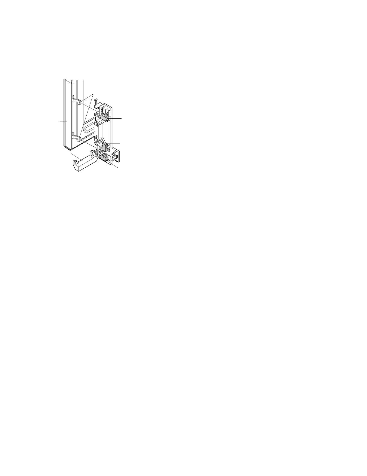
The door is opened by pushing the open button on the control panel,
refer to the Figure D-1. When the open button is pushed, the open but-
ton pushes up the switch lever, and then the switch lever pushes up
the latch head. The latch heads are moved upward and released from
latch hook. Now the door will open.
Figure D-1. Door Open Mechanism.
2. DOOR SENSING AND PRIMARY INTERLOCK
SWITCHES
The primary interlock switch is mounted in the lower position of the
latch hook and the door sensing switch in the secondary interlock sys-
tem is mounted in the upper position of the latch hook. They are acti-
vated by the latch heads on the door. When the door is opened, the
switches interrupt the power to all high voltage components. A cook
cycle cannot take place until the door is firmly closed there by activat-
ing both interlock switches. The secondary interlock system consists
of the door sensing switch and secondary interlock relay located on
the control circuit board.
3. MONITOR SWITCH
The monitor switch is activated (the contacts opened) by the latch
head on the door while the door is closed. The switch is intended to
render the oven inoperative, by means of blowing the monitor fuse,
when the contacts of the secondary interlock relay (RY2) and primary
interlock switch fail to open when the door is opened.
Functions:
1) When the door is opened, the monitor switch contact close (to the
ON condition) due to their being normally closed. At this time the
secondary interlock relay (RY2) and primary interlock switch are in
the OFF condition (contacts open) due to their being normally open
contact switches.
2) As the door goes to a closed position, the monitor switch contacts
are first opened and then the door sensing switch and the primary
interlock switch contacts close. (On opening the door, each of these
switches operate inversely.)
3) If the door is opened, and the secondary interlock relay (RY2) and
primary interlock switch contacts fail to open, the monitor fuse
blows simultaneously with closing of the monitor switch contacts.
CAUTION: BEFORE REPLACING A BLOWN MONITORFUSE TEST
THE DOOR SENSING SWITCH, SECONDARY INTER-
LOCK RELAY (RY2), RE-LAY (RY1), PRIMARY INTER-
LOCK SWITCH AND MONITOR SWITCH FOR PROPER
OPERATION. (REFER TO CHAPTER “TEST PROCE-
DURE”).
NOTE: MONITOR FUSE AND MONITOR SWITCH ARE REPLACED
AS AN ASSEMBLY.
4. TURNTABLE MOTOR
The turntable motor rotates the turntable located on the bottom of the
oven cavity, so that the foods on the turntable cook evenly during
cooking. The turntable may turn in either direction.
5. COOLING FAN MOTOR
The cooling fan motor drives a blade which draws external cool air.
This cool air is directed through the air vanes surrounding the magne-
tron and cools the magnetron. This air is channeled through the oven
cavity to remove steam and vapors given off from the heating foods. It
is then exhausted through the exhausting air vents at the oven cavity.
6. OVEN THERMAL CUT-OUT
The thermal cut-out, located on the top of the oven cavity, is designed
to prevent damage to the oven by fire. If the food load is overcooked,
by either error in cook time or defect in the control unit, the thermal cut-
out will open. Under normal operation, the oven thermal cut-out
remains closed. However, when abnormally high temperatures are
reached within the oven cavity, the oven thermal cut-out will open at
293°F(145°C), causing the oven to shut down.
7. MAGNETRON TEMPERATURE FUSE
The magnetron temperature fuse located near the magnetron is
designed to prevent damage to the magnetron if an over heated condi-
tion develops in the tube due to cooling fan failure, obstructed air
guide, dirty or blocked air intake, etc. Under normal operation, the
magnetron temperature fuse remains closed. However, when abnor-
mally high temperatures are reached within the magnetron, the mag-
netron temperature fuse will open at 302°F(150°C) causing the oven
to shut down.
NOTE: This is a fuse. It does not reset.
8. MONITOR FUSE
1) The monitor fuse blows when the contacts (COM-NO) of the pri-
mary interlock relay (RY2) and secondary interlock switch remain
closed with the oven door open and when the monitor switch
closes.
2) If the wire harness or electrical components are short-circuited, this
monitor fuse blows to prevent an electric shock or fire hazard.
9. NOISE FILER
The noise filter prevents the radio frequency interference that might
flow back in the power circuit.
Door Sensing
Switch
Monitor Switch
Switch Lever
Primary Interlock
Switch
Latch Heads
Door
R408LS
7 – 1
R408LS Service Manual
CHAPTER 7. TROUBLESHOOTING GUIDE
When troubleshooting the microwave oven, it is helpful to follow the Sequence of Operation in performing the checks. Many of the possible causes of
trouble will require that a specific test be performed. These tests are given a procedure letter which will be found in the "Test Procedure "section.
IMPORTANT:
If the oven becomes inoperative because of a blown monitor fuse,
check the monitor switch, relay (RY1) secondary interlock relay (RY2),
door sensing switch and primary interlock switch before replacing the
monitor fuse. If the monitor fuse is replaced, the monitor switch must
also be replaced. Use part FFS-BA033WRKZ or FFS-BA037WRKZ as
an assembly.
IMPORTANT:
Whenever troubleshooting is performed with the power supply cord
disconnected. It may in, some cases, be necessary to connect the
power supply cord after the outer case has been removed, in this
event,
1) Disconnect the power supply cord, and then remove outer case.
2) Open the door and block it open.
3) Discharge high voltage capacitor.
4) Disconnect the leads to the primary of the power transformer.
5) Ensure that the leads remain isolated from other components and
oven chassis by using insulation tape.
6) After that procedure, reconnect the power supply cord.
When the testing is completed,
1) Disconnect the power supply cord, and then remove outer case.
2) Open the door and block it open.
3) Discharge high voltage capacitor.
4) Reconnect the leads to the primary of the power transformer.
5) Reinstall the outer case (cabinet).
6) Reconnect the power supply cord after the outer case is installed.
7) Run the oven and check all functions.
[1] TROUBLESHOOTING CHART
Never touch any part in the circuit with your hand or an uninsulated tool while the power supply is connected.
RE CK A B C D E F F G H RE RE RE J CK CK CK K L NI
POSSIBLE CASE
AND DEFECTIVE PARTS
SHORT IN POWER CORD
SHORT OR OPENED WIRING
MAGNETRON
POWER TRANSFORMER
H.V. RECTIFIER ASSEMBLY
HIGH VOLTAGE CAPACITOR
MAGNETRON TEMPERATURE FUSE
SECONDARY INTERLOCK SYSTEM
PRIMARY INTERLOCK SWITCH
MONITOR SWITCH
MONITOR FUSE
OVEN LAMP
COOLING FAN MOTOR
TURNTABLE MOTOR
TOUCH CONTROL PANEL
WRONG OPERATION
LOW VOLTAGE
DIRTY OVEN CAVITY
KEY UNIT (MEMBRAINE SWITCH)
RELAY (RY1)
FOIL PATTERN ON PWB
NOISE FILTER
CONDITION
PROBLEM
OFF
CONDITION
TTEST PROCEDURE
RE: Replace / CK: Check
COOKING
CONDITION
E
OVEN THERMAL CUT-OUT
M
DEFROST
Home fuse or circuit breaker blows when
power cord is plugged into wall receptacle
Monitor fuse blows when power cord is plug-
ged into wall receptacle.
All letters and indicators do not appear in dis-
play when power cord is first plugged into
wall outlet.
Display does not operate properly when
STOP/CLEAR pad is touched. (Buzzer
should sound and " : " or time of day
should appear in display.)
Oven lamp does not light when door is
opened.
Oven lamp does not go out when door is
closed.
Oven lamp lights but fan motor and turntable
motor do not operate.
Oven does not go into cook cycle when
START pad is touched
Oven seems to be operating but little or no
heat is produced in oven load. (Food incom-
pletely cooked or not cooked at all at end of
cook cycle.)
Oven goes into a cook cycle but extremely
uneven heating is produced in oven load
(food).
Oven does not cook properly when program-
med for Cooking Power P-50 mode. (Oper-
ates properly on Cooking Power P-HI (HIGH)
mode.)
Oven goes into DEFROST but food is not
defrosted well.
R408LS
8 – 1
R408LS Service Manual
CHAPTER 8. TEST PROCEDURES
[1] A: MAGNETRON ASSEMBLY TEST
1. Disconnect the power supply cord, and then remove outer case.
2. Open the door and block it open.
3. Discharge high voltage capacitor.
4. To test for an open filament, isolate the magnetron from the high voltage circuit. A continuity check across the magnetron filament leads should
indicate less than 1 ohm.
5. To test for a shorted magnetron, connect the ohmmeter leads between the magnetron filament leads and chassis ground. This test should indicate
an infinite resistance. If there is little or no resistance the magnetron is grounded and must be replaced.
6. Reconnect all leads removed from components during testing.
7. Reinstall the outer case (cabinet).
8. Reconnect the power supply cord after the outer case is installed.
9. Run the oven and check all functions.
1. MICROWAVE OUTPUT POWER
The following test procedure should be carried out with the microwave oven in a fully assembled condition (outer case fitted).
HIGH VOLTAGES ARE PRESENT DURING THE COOK CYCLE, SO EXTREME CAUTION SHOULD BE OBSERVED.
Power output of the magnetron can be measured by performing a water temperature rise test. This test should only be used if above tests do not indi-
cate a faulty magnetron and there is no defect in the following components or wiring: silicon rectifier, high voltage capacitor and power transformer.
This test will require a 16 ounce (453cc) measuring cup and an accurate mercury thermometer or thermocouple type temperature tester. For accurate
results, the following procedure must be followed carefully:
1. Fill the measuring cup with 16 oz. (453cc) of tap water and measure the temperature of the water with a thermometer or thermocouple tempera-
ture tester. Stir the thermometer or thermocouple through the water until the temperature stabilizes. Record the temperature of the water.
2. Place the cup of water in the oven. Operate oven at POWER 10 (HIGH) selecting more than 60 seconds cook time. Allow the water to heat for 60
seconds, measuring with a stop watch, second hand of a watch or the digital read-out countdown.
3. Remove the cup from the oven and again measure the temperature, making sure to stir the thermometer or thermocouple through the water until
the maximum temperature is recorded.
4. Subtract the cold water temperature from the hot water temperature. The normal result should be 34.8 to 64.6°F(19.3 to 35.9°C) rise in tempera-
ture. If the water temperatures are accurately measured and tested for the required time period the test results will indicate if the magnetron tube
has low power output (low rise in water temperature) which would extend cooking time or high power output (high rise in water temperature) which
would reduce cooking time. Because cooking time can be adjusted to compensate for power output, the magnetron tube assembly should be
replaced only if the water temperature rise test indicates a power output well beyond the normal limits. The test is only accurate if the power supply
line voltage is 120 volts and the oven cavity is clean.
[2] B: POWER TRANSFORMER TEST
1. Disconnect the power supply cord, and then remove outer case.
2. Open the door and block it open.
3. Discharge high voltage capacitor.
4. Disconnect the primary input terminals and measure the resistance of the transformer with an ohmmeter. Check for continuity of the coils with an
ohmmeter. On the R x 1 scale, the resistance of the primary coil should be less than 1 ohm and the resistance of the high voltage coil should be
approximately 159 ohms (RTRN-A746WRZZ) or approximately 150 ohms (RTRN-A745WRZZ); the resistance of the filament coil should be less
than 1 ohm.
5. Reconnect all leads removed from components during testing.
6. Reinstall the outer case (cabinet).
7. Reconnect the power supply cord after the outer case is installed.
8. Run the oven and check all functions.
(HIGH VOLTAGES ARE PRESENT AT THE HIGH VOLTAGE TERMINAL, SO DO NOT ATTEMPT TO MEASURE THE FILAMENT AND HIGH
VOLTAGE.)
[3] C: HIGH VOLTAGE RECTIFIER TEST
1. Disconnect the power supply cord, and then remove outer case.
2. Open the door and block it open.
3. Discharge high voltage capacitor.
4. Isolate the rectifier from the circuit. Using the highest ohm scale of the meter, read the resistance across the terminals and observe, reverse the
leads to the rectifier terminals and observe meter reading. If a short is indicated in both directions, or if an infinite resistance is read in both direc-
tions, the rectifier is probably defective and should be replaced.
R408LS
8 – 2
5. Reconnect all leads removed from components during testing.
6. Reinstall the outer case (cabinet).
7. Reconnect the power supply cord after the outer case is installed.
8. Run the oven and check all functions.
NOTE: Be sure to use an ohmmeter that will supply a forward bias voltage of more than 6.3 volts.
[4] D: HIGH VOLTAGE CAPACITOR TEST
1. Disconnect the power supply cord, and then remove outer case.
2. Open the door and block it open.
3. Discharge high voltage capacitor.
4. If the capacitor is open, no high voltage will be available to the magnetron. Disconnect input leads and check for short or open between the termi-
nals using an ohmmeter.
Checking with a high ohm scale, if the high voltage capacitor is normal, the meter will indicate continuity for a short time and should indicate an
open circuit once the capacitor is charged. If the above is not the case, check the capacitor with an ohmmeter to see if it is shorted between either
of the terminals and case. If it is shorted, replace the capacitor.
5. Reconnect all leads removed from components during testing.
6. Reinstall the outer case (cabinet).
7. Reconnect the power supply cord after the outer case is installed.
8. Run the oven and check all functions.
[5] E: TEMPERATURE FUSE OR THERMAL CUT-OUT TEST
1. Disconnect the power supply cord, and then remove outer case.
2. Open the door and block it open.
3. Discharge high voltage capacitor.
4. Check a continuity across the temperature fuse or thermal cut-out terminals in the table below.
5. An open temperature fuse (Magnetron) indicates overheating of the magnetron. Check for restricted air flow to the magnetron, especially the cool-
ing fan and air guide.
An open thermal cut-out (Oven) indicates overheating of the oven, exchange the thermal cut-out and check inside of oven cavity and for improper
setting of cooking time or operation of control unit. Check for restricted air flow through the vent holes of the oven cavity, especially the cooling fan
and air guide.
6. Reconnect all leads removed from components during testing.
7. Reinstall the outer case (Cabinet).
8. Reconnect the power supply cord after the outer case is installed.
9. Run the oven and check all functions.
CAUTION: IF THE TEMPERATURE FUSE OR THERMAL CUT-OUT INDICATES AN OPEN CIRCUIT AT ROOM TEMPERATURE, REPLACE IT.
[6] F: PRIMARY INTERLOCK SWITCH TEST
1. Disconnect the power supply cord, and then remove outer case.
2. Open the door and block it open.
3. Discharge high voltage capacitor.
4. Isolate the switch and connect the ohmmeter to the common (COM.) and normally open (NO) terminal of the switch. The meter should indicate an
open circuit with the door open and a closed circuit with the door closed. If improper operation is indicated, replace the primary interlock switch.
5. Reconnect all leads removed from components during testing.
6. Reinstall the outer case (cabinet).
7. Reconnect the power supply cord after the outer case is installed.
8. Run the oven and check all functions.
Table: Temperature Fuse and Thermal Cut-out Test
Parts Name Temperature of “ON” condition
(closed circuit).
Temperature of “OFF” condition
(open circuit).
Indication of ohmmeter (When room
temperature is approx. 20°C.)
Temperature fuse 150°C This is not resetable type. Above 150°C (302°F) Closed circuit
Thermal cut-out 145°C This is not resetable type. Above 145°C (293°F) Closed circuit
R408LS
8 – 3
[7] F: SECONDARY INTERLOCK SYSTEM TEST
1. DOOR SENSING SWITCH
1. Disconnect the power supply cord, and then remove outer case.
2. Open the door and block it open.
3. Discharge high voltage capacitor.
4. Isolate the switch and connect the ohmmeter to the common (COM.) and normally open (NO) terminal of the switch. The meter should indicate an
open circuit with the door open and a closed circuit with the door closed. If improper operation is indicated, replace the door sensing switch.
5. Reconnect all leads removed from components during testing.
6. Reinstall the outer case (cabinet).
7. Reconnect the power supply cord after the outer case is installed.
8. Run the oven and check all functions.
NOTE: If the door sensing switch contacts fail in the open position and the door is closed, the cooling fan, turntable and oven light will be activated by
RY1.
2. SECONDARY INTERLOCK RELAY (RY2)
1. Disconnect the power supply cord, and then remove outer case.
2. Open the door and block it open.
3. Discharge high voltage capacitor.
4. Disconnect two (2) wire leads from the male tab terminals of the Secondary Interlock Relay. Check the state of the relay contacts using a ohmme-
ter. The relay contacts should be open. If the relay contacts are closed, replace the circuit board entirely or the relay itself.
5. Reconnect all leads removed from components during testing.
6. Reinstall the outer case (cabinet).
7. Reconnect the power supply cord after the outer case is installed.
8. Run the oven and check all functions.
[8] G: MONITOR SWITCH TEST
1. Disconnect the power supply cord, and then remove outer case.
2. Open the door and block it open.
3. Discharge high voltage capacitor.
4. Before performing this test, make sure that the primary interlock switch and the secondary interlock relay are operating properly, according to the
above Switch Test Procedure. Disconnect the wire lead from the monitor switch (COM) terminal. Check the monitor switch operation by using the
ohmmeter as follows. When the door is open, the meter should indicate a closed circuit. When the monitor switch actuator is pushed by a screw
driver through the lower latch hole on the front plate of the oven cavity with the door opened (in this condition the plunger of the monitor switch is
pushed in), the meter should indicate an open circuit. If improper operation is indicated, the switch may be defective. After testing the monitor
switch, reconnect the wire lead to the monitor switch (COM) terminal and check the continuity of the monitor circuit.
5. Reconnect all leads removed from components during testing.
6. Reinstall the outer case (cabinet).
7. Reconnect the power supply cord after the outer case is installed.
8. Run the oven and check all functions.
Primary
Interlock Switch Monitor Switch
Screw Driver
Ohmmeter
Red White/ White
R408LS
8 – 4
[9] H: BLOWN MONITOR FUSE TEST
1. Disconnect the power supply cord, and then remove outer case.
2. Open the door and block it open.
3. Discharge high voltage capacitor.
4. If the monitor fuse is blown when the door is opened, check the primary interlock switch, secondary interlock relay (RY2), relay (RY1) and monitor
switch according to the “TEST PROCEDURE” for those switches before replacing the blown monitor fuse.
CAUTION: BEFORE REPLACING A BLOWN MONITOR FUSE, TEST THE PRIMARY INTERLOCK SWITCH, SECONDARY INTERLOCK RELAY,
DOOR SENSING SWITCH AND MONITOR SWITCH FOR PROPER OPERATION.
If the monitor fuse is blown by improper switch operation, the monitor fuse and monitor switch must be replaced with “monitor fuse and monitor
switch assembly” part number FFS-BA033WRKZ or FFS-BA037WRKZ, even if the monitor switch operates normally. The monitor fuse and moni-
tor switch assembly is comprised of a 20 ampere fuse and switch.
5. Reconnect all leads removed from components during testing.
6. Reinstall the outer case (cabinet).
7. Reconnect the power supply cord after the outer case is installed.
8. Run the oven and check all functions.
[10] I: NOISE FILTER TEST
1. Disconnect the power supply cord, and then remove outer case.
2. Open the door and block it open.
3. Discharge high voltage capacitor.
4. Disconnect the lead wires from the terminal the noise filter. Using an ohmmeter, check between
the terminals as described in the following table. If incorrect readings are obtained, replace the
noise filter.
5. Reconnect all leads removed from components during testing.
6. Reinstall the outer case (cabinet).
7. Reconnect the power supply cord after the outer case is installed.
8. Run the oven and check all functions.
[11] J: TOUCH CONTROL PANEL ASSEMBLY TEST
The touch control panel consists of circuits including semiconductors such as LSI, ICs, etc. Therefore, unlike conventional microwave ovens, proper
maintenance cannot be performed with only a voltmeter and ohmmeter.
In this service manual, the touch control panel assembly is divided into two units, Control Unit and Key Unit, and also the Control Unit is divided into
two units, CPU Unit and Power Unit, and troubleshooting by unit replacement is described according to the symptoms indicated.
Before testing,
1) Disconnect the power supply cord and then remove outer case.
2) Open the door and block it open.
3) Discharge high voltage capacitor.
4) Disconnect the leads to the primary of the power transformer.
5) Ensure that these leads remain isolated from other components and oven chassis by using insulation tape.
1. Key Unit
1) Reinstall the outer case (cabinet).
2) Reconnect the power supply cord after the outer case is installed.
3) Run the oven and check all functions.
The following symptoms indicate a defective key unit.
a) When touching the pads, a certain pad produces no signal at all.
b) When touching a number pad, two figures or more are displayed.
c) When touching the pads, sometimes a pad produces no signal.
2. Control Unit.
The following symptoms indicate a defective control unit.
MEASURING POINT INDICATION OF OHMMETER
Between N and L Open circuit.
Between terminal N and WHITE Short circuit.
Between terminal L and RED Short circuit.
FUSE 20A
NOISE FILTER
NOISE SUPPRESSION COIL
LINE CROSS CAPACITOR
0.22μF / AC 250V
LINE BYPASS
CAPACITOR
0.0033μF / AC 250V
LINE BYPASS
CAPACITOR
0.0033μF / AC 250V
L
REDWHITE
N
R408LS
8 – 5
1) In connection with pads.
a) When touching the pads, a certain group of pads do not produce a signal.
b) When touching the pads, no pads produce a signal.
2) In connection with indicators
a) At a certain digit, all or some segments do not light up.
b) At a certain digit, brightness is low.
c) Only one indicator does not light.
d) The corresponding segments of all digits do not light up; or they continue to light up.
e) Wrong figure appears.
f) A certain group of indicators do not light up.
g) The figure of all digits flicker.
3) Other possible problems caused by defective control unit.
a) Buzzer does not sound or continues to sound.
b) Clock does not operate properly.
c) Cooking is not possible.
3. If the Key unit or the Control unit is defective.
1) Disconnect the power supply cord, and then remove outer case.
2) Open the door and block it open.
3) Discharge high voltage capacitor.
4) Replace the Control unit assembly.
5) Reconnect all leads removed from components during testing.
6) Reinstall the outer case (cabinet).
7) Reconnect the power supply cord after the outer case is installed.
8) Run the oven and check all functions.
4. When testing is completed,
1) Disconnect the power supply cord and then remove outer case.
2) Open the door and block it open.
3) Discharge high voltage capacitor.
4) Reconnect all leads removed from components during testing.
5) Reinstall the outer case (cabinet).
6) Reconnect the power supply cord after the outer case is installed.
7) Run the oven and check all functions.
[12] K: KEY UNIT TEST
If the display fails to clear when the STOP/CLEAR pad is depressed, first verify the flat ribbon cable is making good contact, verify that the door sens-
ing switch (stop switch) operates properly; that is the contacts are closed when the door is closed and open when the door is open. If the door sensing
switch (stop switch) is good, disconnect the flat ribbon cable that connects the key unit to the control unit and make sure the door sensing switch is
closed (either close the door or short the door sensing switch connector). Use the key unit matrix indicated on the control panel schematic and place
a jumper wire between the pins that correspond to the STOP/CLEAR pad making momentary contact.If the control unit responds by clearing with a
beep the key unit is faulty and must be replaced. If the control unit does not respond, it is faulty and must be replaced. If a specific pad does not
respond, the above method may be used (after clearing the control unit) to determine if the control unit or keypad is at fault.
[13] L: RELAY TEST
1. Disconnect the power supply cord, and then remove outer case.
2. Open the door and block it open.
G5 G4 G3G8
G10
G11
G12
G13 NC
G7 G6
G9
G2 G1
REHEAT
4
1
7
2
5
8
0
TIMER
CLOCK
6
3
9
COOK
SOFTEN MELT
WARM
POPCORN
DEFROST
POWER
LEVEL
STOP
CLEAR
START
MINUTE
PLUS
R408LS
8 – 6
3. Discharge high voltage capacitor.
4. Disconnect the leads to the primary of the power transformer.
5. Ensure that these leads remain isolated from other components and oven chassis by using insulation tape.
6. After that procedure, re-connect the power supply cord.
7. Remove the outer case and check voltage between the cabinet side terminal of the relay RY1 and the lower side terminal of the relay RY2 on the
control unit with an A.C. voltmeter.
The meter should indicate 120 volts, if not check oven circuit.
RY1 and RY2 Relay Test
These relays are operated by D.C. voltage
Check voltage at the relay coil with a D.C. voltmeter during the microwave cooking operation.
DC. voltage indicated ................. Defective relay.
DC. voltage not indicated ........... Check diode which is connected to the relay coil. If diode is good, control unit is defective.
8. Disconnect the power supply cord and then remove outer case.
9. Open the door and block it open.
10.Discharge high voltage capacitor.
11. Reconnect all leads removed from components during testing.
12.Reinstall the outer case (cabinet).
13.Reconnect the power supply cord after the outer case is installed.
14.Run the oven and check all functions.
[14] M: DEFROST TEST
WARNING: The oven should be fully assembled before following procedure.
1. Open the door.
2. Place one cup of water in the center of the turntable tray in the oven cavity.
3. Close the door, touch the “DEFROST“ pad once.
4. Press “2”, then press “5”.
5. Touch the “START “ pad.
6. The oven is in Defrost cooking condition.
7. The oven will operate as follows.
8. If improper operation is indicated, the control unit is probably defective and should be checked.
[15] N: FOIL PATTERN ON THE PRINTED WIRING BOARD TEST
To protect the electronic circuits, this model is provided with a fine foil pattern added to the primary on the PWB, this foil pattern acts as a fuse.
1. Foil pattern check and repairs.
1) Disconnect the power supply cord and then remove outer case.
2) Open the door and block it open.
3) Discharge high voltage capacitor.
4) Follow the troubleshooting guide given below for repair.
RELAY SYMBOL OPERATIONAL VOLTAGE CONNECTED COMPONENTS
RY1 Approx. 12.0V D.C. Oven lamp / Turntable motor / Cooling fan motor
RY2 Approx. 12.0V D.C. Power transformer
MENU 1ST STAGE 2ND STAGE 3RD STAGE
Steaks/Chops LEVEL TIME LEVEL TIME LEVEL TIME
0.5lb 60% 20sec. 40% 20sec. 30% 45sec.
STEPS OCCURRENCE CAUSE OR CORRECTION
1 Only pattern at “a” is broken. *Insert jumper wire J1 and solder.
2 Pattern at “a” and “b” are broken. Replace the control unit.
R408LS
8 – 7
5) Make a visual inspection of the varistor. Check for burned damage and examine
the transformer with a tester for the presence of layer short-circuit (check the
primary coil resistance which is approximately 563Ω±10%). If any abnormal
condition is detected, replace the control unit.
6) Reconnect all leads removed from components during testing.
7) Reinstall the outer case (cabinet).
8) Reconnect the power supply cord after the outer case is installed.
9) Run the oven and check all functions.
2. Follow the troubleshooting guide given below, if indicator does not light up after
above check and repairs are finished.
1) Disconnect the power supply cord and then remove outer case.
2) Open the door and block it open.
3) Discharge high voltage capacitor.
4) Disconnect the leads to the primary of the power transformer.
5) Ensure that these leads remain isolated from other components and oven chassis by using insulation tape.
6) After that procedure, reconnect the power supply cord.
7) Follow the troubleshooting guide given below for repair.
8) Disconnect the power supply cord and then remove outer case.
9) Open the door and block it open.
10)Discharge high voltage capacitor.
11)Reconnect all leads removed from components during testing.
12)Reinstall the outer case (cabinet).
13)Reconnect the power supply cord after the outer case is installed.
14)Run the oven and check all functions.
STEPS OCCURRENCE CAUSE OR CORRECTION
1The rated AC voltage is not present between the cabinet side terminal of
the relay RY1 and the lower side terminal of the relay RY2. Check supply voltage and oven power cord.
2The rated AC voltage is present at primary side of low voltage trans-
former.
Low voltage transformer or secondary circuit defective.
Check and replace control unit.
a
bd
c
  • Page 1 1
  • Page 2 2
  • Page 3 3
  • Page 4 4
  • Page 5 5
  • Page 6 6
  • Page 7 7
  • Page 8 8
  • Page 9 9
  • Page 10 10
  • Page 11 11
  • Page 12 12
  • Page 13 13
  • Page 14 14
  • Page 15 15
  • Page 16 16
  • Page 17 17
  • Page 18 18
  • Page 19 19
  • Page 20 20
  • Page 21 21
  • Page 22 22
  • Page 23 23
  • Page 24 24
  • Page 25 25
  • Page 26 26
  • Page 27 27
  • Page 28 28
  • Page 29 29
  • Page 30 30
  • Page 31 31
  • Page 32 32
  • Page 33 33
  • Page 34 34
  • Page 35 35
  • Page 36 36
  • Page 37 37
  • Page 38 38
  • Page 39 39
  • Page 40 40

Sharp R-408LS Owner's manual

Category
Microwaves
Type
Owner's manual
This manual is also suitable for

Ask a question and I''ll find the answer in the document

Finding information in a document is now easier with AI