
PART No. 9374318544-04
AIR CONDITIONER
English
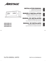
INDOOR UNIT (Compact cassette type)
FrançaisEspañol
UNITÉ INTÉRIEURE (Type cassette compacte)
UNIDAD INTERIOR (Tipo casete)
INSTALLATION MANUAL
For authorized service personnel only.
MANUEL D’INSTALLATION
MANUAL DE INSTALACIÓN
Pour le personnel agréé uniquement.
Únicamente para personal de servicio autorizado.

En-1
1. SAFETY PRECAUTIONS
Contents
1. SAFETY PRECAUTIONS ..........................................................................1
1.1. IMPORTANT! Please read before starting..........................................1
1.2. SPECIAL PRECAUTIONS ..................................................................1
2. ABOUT THIS PRODUCT...........................................................................2
2.1. Precautions for using R410A refrigerant .............................................2
2.2. Special tools for R410A refrigerant .....................................................2
2.3. For authorized service personnel only. ...............................................3
2.4. Accessories ........................................................................................3
2.5. Cassette grille accessories .................................................................4
2.6. Optional parts .....................................................................................4
3. GENERAL SPECIFICATIONS ...................................................................4
3.1. Type of copper pipe and insulation material .......................................4
3.2. Additional materials required for installation .......................................4
3.3. Operating range ..................................................................................4
3.4. Electrical requirement ........................................................................5
4. INSTALLATION WORK .............................................................................5
4.1. Selecting the installation location .......................................................5
4.2. Installation dimensions .......................................................................5
4.3. Installation the unit ..............................................................................6
5. INSTALLING DRAIN PIPES ......................................................................7
6. PIPE INSTALLATION ................................................................................8
6.1. Selecting the pipe material .................................................................8
6.2. Pipe requirement ................................................................................8
6.3. Flare connection .................................................................................9
6.4. Installing heat insulation ...................................................................10
7. ELECTRICAL WIRING ............................................................................10
7.1. Wiring system diagram ..................................................................... 11
7.2. Connection cable preparation ........................................................... 11
7.3. Connection of wiring ......................................................................... 11
8. REMOTE CONTROLLER SETTING .......................................................12
8.1. Installing the remote controller .........................................................12
8.2. Setting the DIP switches ...................................................................13
9. CASSETTE GRILLE INSTALLATION ......................................................13
9.1. Remove the intake grille ...................................................................13
9.2. Install panel to unit ............................................................................14
9.3. Attach the intake grille ......................................................................14
10. FUNCTION SETTING ...........................................................................14
11. SPECIAL INSTALLATION METHODS ...................................................17
12. TEST RUN .............................................................................................18
13. OPTIONAL KIT INSTALLATION ............................................................18
14. CUSTOMER GUIDANCE ......................................................................18
15. ERROR CODES ....................................................................................19
INSTALLATION MANUAL
PART No. 9374318544-04
INDOOR UNIT (Compact cassette type)
1.1. IMPORTANT! Please read before starting
This air conditioning system meets strict safety and operating
standards.
As the installer or service person, it is an important part of
your job to install or service the system so it operates safely
and effi ciently.
For safe installation and trouble-free operation, you must:
• Carefully read this instruction booklet before beginning.
• Follow each installation or repair step exactly as shown.
• Observe all local, state, and national electrical codes.
• Pay close attention to all warning, and caution notices given
in this manual.
WARNING:
This symbol refers to a hazard or unsafe
practice which can result in severe personal
injury or death.
CAUTION:
This symbol refers to a hazard or unsafe
practice which can result in personal injury
and the potential for product or property
damage.
• Hazard alerting symbols
Electrical
Safety/alert
If Necessary, Get Help
These instructions are all you need for most installation sites
and maintenance conditions. If you require help for a special
problem, contact our sales/service outlet or your certified
dealer for additional instructions.
In Case of Improper Installation
The manufacturer shall in no way be responsible for improper
installation or maintenance service, including failure to follow
the instructions in this document.
1.2. SPECIAL PRECAUTIONS
When Wiring
ELECTRICAL SHOCK CAN CAUSE SEVERE PERSONAL
INJURY OR DEATH. ONLY A QUALIFIED, EXPERIENCED
ELECTRICIAN SHOULD ATTEMPT TO WIRE THIS SYSTEM.
• Do not supply power to the unit until all wiring and tubing
are completed or reconnected and checked.
• Highly dangerous electrical voltages are used in this sys-
tem. Carefully refer to the wiring diagram and these instruc-
tions when wiring. Improper connections and inadequate
earthing (grounding) can cause accidental injury or death.
• Earth (Ground) the unit following local electrical codes.
• Connect all wiring tightly. Loose wiring may cause overheat-
ing at connection points and a possible fi re hazard.
When Transporting
Be careful when picking up and moving the indoor and
outdoor units. Get a partner to help, and bend your knees
when lifting to reduce strain on your back. Sharp edges or thin
aluminium fi ns on the air conditioner can cut your fi ngers.
When Installing...
...In a Ceiling or Wall
Make sure the ceiling/wall is strong enough to hold the unit’s
weight. It may be necessary to construct a strong wood or
metal frame to provide added support.
...In a Room
Properly insulate any tubing run inside a room to prevent
“sweating” that can cause dripping and water damage to walls
and fl oors.
...In Moist or Uneven Locations
Use a raised concrete pad or concrete blocks to provide a
solid, level foundation for the outdoor unit. This prevents water
damage and abnormal vibration.
...In an Area with High Winds
Securely anchor the outdoor unit down with bolts and a metal
frame.
Provide a suitable air baffl e.

En-2
...In a Snowy Area (for Heat Pump-type Systems)
Install the outdoor unit on a raised platform that is higher than
drifting snow.
When Connecting Refrigerant Tubing
• Keep all tubing runs as short as possible.
• Use the fl are method for connecting tubing.
• Apply refrigerant lubricant to the matching surfaces of the
fl are and union tubes before connecting them, then tighten
the nut with a torque wrench for a leak-free connection.
• Check carefully for leaks before opening the refrigerant
valves.
When Servicing
• Turn the power OFF at the main circuit breaker panel
before opening the unit to check or repair electrical parts
and wiring.
• Keep your fingers and clothing away from any moving
parts.
• Clean up the site after you finish, remembering to check
that no metal scraps or bits of wiring have been left inside
the unit being serviced.
• After installation, explain correct operation to the customer,
using the operating manual.
WARNING
Never touch electrical components immediately
after the power supply has been turned off. Electri-
cal shock may occur. After turning off the power,
always wait 5 minutes or more before touching
electrical components.
2. ABOUT THIS PRODUCT
2.1.
Precautions for using R410A refrigerant
The basic installation work procedures are the same
as conventional refrigerant models.
However, pay careful attention to the following points:
Since the working pressure is 1.6 times higher than
that of conventional refrigerant (R22) models, some
of the piping and installation and service tools are
special. (See the following table.)
Especially, when replacing a conventional refriger-
ant (R22) model with a new refrigerant R410A model,
always replace the conventional piping and fl are nuts
with the R410A piping and fl are nuts.
Models that use refrigerant R410A have a different
charging port thread diameter to prevent errone-
ous charging with conventional refrigerant (R22)
and for safety. Therefore, check beforehand.
[The charging port thread diameter for R410A is
1/2-20 UNF.]
Be careful that foreign matter (oil, water, etc.)
does not enter the piping than with conventional
refrigerant (R22) models. Also, when storing the
piping, securely seal the openings by pinching,
taping, etc.
When charging the refrigerant, take into account
the slight change in the composition of the gas
and liquid phases. A always charge from the liquid
phase where refrigerant composition is stable.
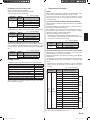
2.2. Special tools for R410A refrigerant
Tool name Contents of change
Gauge
manifold
Pressure is high and cannot be measured
with a R22 gauge. To prevent erroneous
mixing of other refrigerants, the diameter
of each port has been changed.
It is recommended the gauge with seals
-30 inHg to 768 psi (-0.1 to 5.3 MPa) for
high pressure. -30 inHg to 551 psi (-0.1 to
3.8 MPa) for low pressure.
Charge
hose
To increase pressure resistance, the hose
material and base size were changed.
Vacuum
pump
A conventional vacuum pump can be used
by installing a vacuum pump adapter.
Gas leakage
detector
Special gas leakage detector for HFC
refrigerant R410A.
Copper pipes
It is necessary to use seamless copper pipes and it is desirable
that the amount of residual oil is less than 0.004 oz/100 ft
(40 mg/10 m). Do not use copper pipes having a collapsed,
deformed or discolored portion (especially on the interior
surface). Otherwise, the expansion value or capillary tube
may become blocked with contaminants. As an air conditioner
using R410A incurs pressure higher than when using R22, it
is necessary to choose adequate materials. Thicknesses of
copper pipes used with R410A are as shown in the table. (Refer
to “3.1. Type of copper pipe and insulation material”) Never
use copper pipes thinner than that in the table even when it is
available on the market.

En-3
WARNING
Do not use the existing (for R22) piping and fl are
nuts.
• If the existing materials are used, the pressure inside
the refrigerant cycle will rise and cause failure, injury,
etc. (Use the special R410A materials.)
When installing and relocating the air conditioner,
do not mix gases other than the specifi ed refrigerant
(R410A) to enter the refrigerant cycle.
• If air or other gas enters the refrigerant cycle, the
pressure inside the cycle will rise to an abnormally
high value and cause failure, injury, etc.
2.3. For authorized service personnel only.
WARNING
For the air conditioner to operate satisfactorily, in-
stall it as outlined in this installation manual.
Connect the indoor unit and outdoor unit with the
air conditioner piping and cords available from your
local distributor. This installation manual describes
the correct connections using the installation set
available from your local distributor.
Installation work must be performed in accordance
with national wiring standards by authorized per-
sonnel only.
Do not turn on the power until all installation work is
complete.
CAUTION
This installation manual describes how to install the in-
door unit only.
To install the outdoor unit, refer to the installation manu-
al included with the outdoor unit.
Be careful not to scratch the air conditioner when
handling it.
After installation, explain correct operation to the
customer, using the operating manual.
All Fujitsu General products are manufactured to
metric units and tolerances. United States custom-
ary units are provided for reference only. In cases
where exact dimensions and tolerances are re-
quired, always refer to metric units.
2.4. Accessories
WARNING
For installation purposes, be sure to use the parts
supplied by the manufacturer or other prescribed
parts. The use of non-prescribed parts can cause
serious accidents such as the unit to fall, water leak-
age, electric shock, or fi re.
The following installation parts are furnished. Use
them as required.
Keep the Installation Manual in a safe place and do
not discard any other accessories until the installa-
tion work has been completed.
Do not discard any accessories needed for installation
until the installation work has been completed.
Name and Shape Q’ty Application
Operating Manual
1
Installation Manual
1
(This book)
Coupler heat
insulation
(Small)
1
For indoor side pipe
joint (Liquid pipe)
Coupler heat
insulation
(Large)
1
For indoor side pipe
joint (Gas pipe)
Special nut A
(Large fl ange)
4
For installing indoor
unit
Special nut B
(Small fl ange)
4
For installing indoor
unit
Template
(Carton top)
1
For ceiling openings
cutting
Also used as packing
Drain Hose Assy
1
For installing drain pipe
3/4 in. (19 mm) [O.D.
1-1/16 in. (27 mm)]
Hose Band Assy
1
For installing drain pipe
(3/4 in.)
Drain hose insulation
1
For installing drain
hose
Wired Remote
Controller
1
Remote Controller
Cable
1
For connecting the
remote controller
Tapping screw
2
For installing the wired
remote controller

En-4
2.5. Cassette grille accessories
Name and Shape Q’ty Application
Connector cover
1
For covering connector
Tapping Screw
(M5 × 12 mm)
4
For mounting cassette
grille
Tapping Screw
(M4 × 12 mm) 1
For mounting connec-
tor cover
L angle
2
For mounting the Hook
Wire to the Cassette
grille
Hook wire
2
For suspending the
Cassette grille
Screw [pitch small]
(M4 × 10 mm)
2
For mounting the Hook
Wire (for metals)
Screw [pitch large]
(M4 × 10 mm)
4
For mounting the L
angle and Hook wire
(for resins)
2.6. Optional parts
Parts name Model No. Application
Wireless Remote
Controller
UTY-LNHUM
For air conditioner
operation
Wired Remote
Controller
UTY-RNNUM
For air conditioner
operation
Simple Remote
Controller
UTY-RSNUM
For air conditioner
operation
Insulation kit for
High humidity
UTZ-KXGC
Install when the
condition under the
roof is over 80% in
humidity and over
30°C in temperature.
External connect kit UTY-XWZX
For control input/out-
put port
Fresh air intake kit UTZ-VXAA To take fresh air
3. GENERAL SPECIFICATIONS
This INSTALLATION MANUAL briefl y outlines where and
how to install the air conditioning system. Please read over
the entire set of instructions for the indoor and outdoor units
and make sure all accessory parts listed are with the system
before beginning.
3.1. Type of copper pipe and insulation material
CAUTION
Refer to the Installation Manual for the outdoor unit
for description of allowable pipe length and height
difference.
Copper tubing for connecting the outdoor unit to the indoor
unit and insulation material is available for purchase locally.
When you purchase them, please specify the following.
• Deoxidized annealed copper pipe for refrigerant piping as
shown in the table.
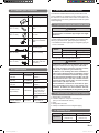
MODEL
Diameter
Liquid pipe Gas pipe
AU7/9/12 1/4 in. (6.35 mm) 3/8 in. (9.52 mm )
AU18 1/4 in. (6.35 mm) 1/2 in. (12.70 mm)
• Use pipe with water-resistant heat insulation.
CAUTION
Install heat insulation around both the gas and liq-
uid pipes. Failure to do so may cause water leaks.
Use heat insulation with heat resistance above
248 °F (120 °C). (Reverse cycle model only)
In addition, if the humidity level at the installation lo-
cation of the refrigerant piping is expected to exceed
70%, install heat insulation around the refrigerant pip-
ing. If the expected humidity level is 70-80%, use heat
insulation that is 9/16 in. (15 mm) or thicker and if the
expected humidity exceeds 80%, use heat insulation
that is 13/16 in. (20 mm) or thicker.
If heat insulation is used that is not as thick as speci-
fied, condensation may form on the surface of the
insulation. In addition, use heat insulation with heat
conductivity of 0.045 W/(m•K) or less [at 68 °F (20 °C)].
3.2. Additional materials required for installation
A. Refrigeration (armored) tape
B. Insulated staples or clamps for connecting wire
(See your local electrical codes.)
C. Putty
D. Refrigeration lubricant
E. Clamps or saddles to secure refrigerant piping
3.3. Operating range
Cooling/Dry Mode Heating Mode
Temperature
About 64 to 90 °F
(18 to 32 °C)
About 60 to 88°F
(16 to 31 °C)
Humidity
About 80% or less ─

En-5
CAUTION
Do not use the unit for special purposes, such as
storing food, raising animals, growing plants, or
preserving precision devices or art objects.
It can degrade the quality of the preserved or stored
objects.
Do not install where there is the danger of combus-
tible gas leakage.
Do not install the unit near a source of heat, steam,
or fl ammable gas.
Install the unit where drainage does not cause any
trouble.
Install the indoor unit, outdoor unit, power supply
cable, and remote controller cable at least 40 in.
(1 m) away from a television or radio receivers.
The purpose of this is to prevent TV reception
interference or radio noise. (Even if they are installed
more than 40 in. (1 m) apart, you could still receive
noise under some signal conditions.)
If children under 10 years old may approach the unit,
take preventive measures so that they cannot reach
the unit.
Use the “Insulation kit for high humidity” (option),
when the condition under the roof is over 80% in
humidity and over 30°C in temperature. Otherwise,
there is a risk of condensation on the ceiling.
Decide the mounting position with the customer as
follows:
(1)
Install the indoor unit in a location having suffi cient strength
to support the weight of the indoor unit.
(2) The inlet and outlet ports should not be obstructed; the air
should be able to blow all over the room.
(3) Leave the space required to service the air conditioner.
(4) The ceiling rear height as shown in the fi gure.
(5) Locate where the air can be distributed evenly throughout
the room by the unit.
(6)
Locate where drainage can be extracted outdoors easily.
(7
) Install the unit where noise and vibration is not amplifi ed.
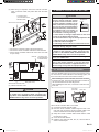
4.2. Installation dimensions
Obstruc
tion
8 ft
(2.4 m) or more
40 in.
(1 m) or more
40 in.
(1 m) or more
Floor
Strong and durable ceiling
11 in.
(262 mm)
or more
3.4. Electrical requirement
Always make the air conditioner power supply a special
branch circuit and provide a special switch and receptacle.
Do not extend the power cable.
WARNING
Refer to local codes for acceptable cable type.
Cable Cable size Remarks
Connection cable 14AWG
3 cable + Earth (Ground)
1Φ 208/230 V
Max. Cable Length: Limit voltage drop to less than 2%. In-
crease cable gauge if voltage drop is 2% or more.
4. INSTALLATION WORK
Install the air conditioner as follows:
4.1. Selecting the installation location
Correct initial installation location is important because it is
diffi cult to move unit after it is installed.
WARNING
Install the air conditioner in a location which can with-
stand a load of at least 3 times the weight of the main
unit and which will not amplify sound or vibration. If the
installation location is not strong enough, the indoor unit
may fall and cause injuries.
MODEL
Withstandable weight
(Unit weight x 3*)
AU7/9/12/18 117 Lbs (53kg)
*In accordance with UL standards.
CAUTION
Do not install the unit in the following areas:
• Area with high salt content, such as at the sea-
side.
It will deteriorate metal parts, causing the parts
to fail or the unit to leak water.
• Area fi lled with mineral oil or containing a large
amount of splashed oil or steam, such as a
kitchen.
It will deteriorate plastic parts, causing the parts
to fail or the unit to leak water.
• Area that generates substances that adversely
affect the equipment, such as sulfuric gas, chlo-
rine gas, acid, or alkali.
It will cause the copper pipes and brazed joints
to corrode, which can cause refrigerant leakage.
• Area that can cause combustible gas to leak,
contains suspended carbon fi bers or fl ammable
dust, or volatile infl ammables such as paint thin-
ner or gasoline.
If gas leaks and settles around the unit, it can
cause a fi re.
• Area where animals may urinate on the unit or
ammonia may be generated.

En-6
• This product can be installed at a height of up to 10 ft (3 m).
However, 7000, 9000 Btu/h models cannot be installed in
high ceilings.
Perform the Function Setting on the remote controller in ac-
cordance with the installed height. (See 10. FUNCTION SET-
TING)
Discharge direction setting
• The discharge direction can be selected as shown as
follows.
(4 directions)
(3 directions)
4 (100) or more*
Unit: in. (mm)
*Please ensure
suffi cient Service
access during
installation.
* For a 3-way outlet, make sure to perform the Function Set-
ting on the remote controller. Also, make sure to use the
optional shutter panel to block the outlet.
* The ceiling height cannot be set in the 3-way outlet mode.
Therefore, do not change the setting in the “Ceiling height”
at
10. FUNCTION SETTING and 12. TEST RUN.
* When the outlet is shut, be sure to install the optional Air
outlet shutter plate kit.
For the details of installation, please refer to Installation
Manual of kit.
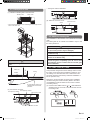
4.3. Installation the unit
4.3.1. Position the ceiling hole and hanging bolts
Ceiling openings and hanger bolt installation diagram
WARNING
Install the air conditioner in a location which can with-
stand a load of at least 5 times the weight of the main
unit and which will not amplify sound or vibration. If the
installation location is not strong enough, the indoor
unit may fall and cause injuries.
If the unit is only attached to the ceiling panel frame
there is a risk that the unit will come loose. Please take
precaution.
When fastening the hangers, make the bolt positions
uniform.
Perform fi nal tightening by tightening the double nut
fi rmly.
20-7/8 (530) (Hanger bolt position)
21-1/4 (540) (Hanger bolt position)
22-7/16 (570) (Indoor unit)
22-13/16 to 26 (580 to 660) (Ceiling openings)
27-9/16 (700) (Cassette grille)
5-5/16 (135)
9-13/16 (250)
2-15/16 (75)
Drain pipe (O.D. ø1 (26.1))
1-9/16 (40) 3-7/8 (99)
4 (102)
4-1/2 (114)
8-7/16 (215)
1-3/16
(30)
10-5/16 (262)
1-3/16 (30)
2-5/16 (58)
4-13/16 (123)
Ceiling
Control box
Liquid pipe
Gas pipe
Be sure to leave service access for future service at the designated
position.
5-14/16 to 7-7/8 (150 to 200)
Min. 17-11/16 (450)
Min. 17-11/16 (450)
Service access
Unit: in. (mm)
Unit: in. (mm)
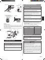
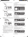
4.3.2. Body installation
(1) Install Special nut A, then Special nut B onto the hanger
bolt.
(2) Raise the body and mount its hooks onto the hanger bolt
between the special nuts.
(3) Turn Special nut B to adjust the height of the body.
Hanger bolt size Used Nuts
M10 Accessories
M8
Locally purchased*
5/16 or 3/8 in.
*
Use a fl ange nut or with a washer.

En-7
Special nut A
Special nut B
Hook
Hanger bolt
1-3/16 (30)
or more
After installing the
body, tighten the nuts.
3/4 (19)
Ceiling
Unit: in. (mm)
4.3.3. Leveling
Using a level gauge, or vinyl hose fi lled with water, fi ne adjust
so that the body is level.
Inclined installation so as the drain pipe side is higher may
cause a malfunction of the fl oat switch, and may cause water
leakage.
Vinyl hoses
Drain pipe
5. INSTALLING DRAIN PIPES
WARNING
Do not insert the drain piping into the sewer where
sulfurous gas occurs. (Heat exchange erosion may
occur)
Insulate the parts properly so that water will not drip
from the connection parts.
Check for proper drainage after installation by using
the visible portion of transparent drain port and the
drain piping fi nal outlet on the body.
CAUTION
Do not apply adhesive agent on the drain port of the
body. (Use the attached drain hose assembly to con-
nect the drain piping)
Note: Install the drain pipe.
Install the drain pipe with downward gradient (1/50 to
1/100) and so there are no rises or traps in the pipe.
Use general hard polyvinyl chloride pipe [3/4 in. (O.D.
1-1/16 in)] and connect it with adhesive (polyvinyl chlo-
ride) so that there is no leakage.
When the pipe is long, install supporter.
Do not perform air bleeding.
Always heat insulate indoor section of drain pipe.
If it is impossible to have suffi cient gradient of pipe, per-
form drain lift-up.
Pipe size
Drain pipe 3/4 in. (O.D. 1-1/16 in.)
Hanging fi ttings
59-1/16 to 6 ft 3/4in. (1.5 to 2 m)
3/4 in.
Downward gradient 1/100 to 1/50
Rise
PROHIBITED:
Trap
Air bleeding
When lifting up drain:
•
Height of inclined pipe should be less than 27-9/16 in. (700 mm)
from the ceiling. A rise dimension over this range will cause leakage.
•
Lift up the pipe vertically at the position of 11-13/16 in. (300 mm)
or less from the unit.
11-13/16 in. (300 mm) or less
3/4 in.
local arrangement
27-9/16 in.
(700 mm) or less
Horizontal or
upward gradient
Downward gradi-
ent 1/100 to 1/50
O.D.1-5/16 in. (33 mm) or more
Downward gradient 1/100 to 1/50
27-9/16 in.
(700 mm) or less
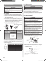
Installation procedure
1) Install the attached drain hose to the drain port of the body.
Install the hose band from the top of the hose within the
shown in the fi gure area.
2) Use PVC glue to glue the drain piping (PVC pipe [3/4 in.
(O.D. 1-1/16 in.)]) to the drain hose assembly.
(Apply color adhesive agent evenly until the gauge line and
seal)
3) Check the drainage. (See separate diagram)
4) Install the heat insulation.
5) Use the attached heat insulation to insulate the drain port
and hose band.
Install the knob facing upward
Attach hose band
(Accessories)
Locally installed
PCV pipe
Attach drain hose
(Accessories)
Attach heat insulation
(Accessories)

En-8
6.1. Selecting the pipe material
CAUTION
Do not use existing pipes.
Use pipes that have clean external and internal sides without
any contamination which may cause trouble during use, such
as sulfur, oxide, dust, cutting waste, oil, or water.
It is necessary to use seamless copper pipes.
Material : Phosphor deoxidized seamless copper pipes
It is desirable that the amount of residual oil is less than
0.004 oz/100 ft (40 mg/10 m).
Do not use copper pipes that have a collapsed, deformed,
or discolored portion (especially on the interior surface).
Otherwise, the expansion valve or capillary tube may become
blocked with contaminants.
Improper pipe selection will degrade performance. As an air
conditioner using R410A incurs pressure higher than when
using conventional refrigerant, it is necessary to choose
adequate materials.
•
Thicknesses of copper pipes used with R410A are as
shown in the table.
•
Never use copper pipes thinner than those indicated in the
table even if they are available on the market.
Thicknesses of Annealed Copper Pipes (R410A)
Pipe outside diameter
[in. (mm)]
Thickness [in. (mm)]
1/4 (6.35) 0.032 (0.80)
3/8 (9.52) 0.032 (0.80)
1/2 (12.70) 0.032 (0.80)
5/8 (15.88) 0.039 (1.00)
3/4 (19.05) 0.047 (1.20)
6.2. Pipe requirement
CAUTION
Refer to the Installation Manual of the outdoor unit for
description of the length of connecting pipe or for difference
of its elevation.
• Use pipe with water-resistant heat insulation.
CAUTION
Install heat insulation around both the gas and liquid pipes.
Failure to do so may cause water leaks.
Use heat insulation with heat resistance above 248 °F
(120 °C). (Reverse cycle model only)
In addition, if the humidity level at the installation location
of the refrigerant piping is expected to exceed 70%, install
heat insulation around the refrigerant piping. If the expected
humidity level is 70-80%, use heat insulation that is 9/16 in.
(15 mm) or thicker and if the expected humidity exceeds
80%, use heat insulation that is 13/16 in. (20 mm) or thicker.
If heat insulation is used that is not as thick as specified,
condensation may form on the surface of the insulation. In
addition, use heat insulation with heat conductivity of 0.045
W/(m·K) or less [at 68 °F (20°C)].
Hose band
Unit: in. (mm)
3/16 to 6/16 (5 to 10)
13/16 (20)
13/16 (20)
Transparent
visible portion
Wind the attached heat insulation
around the hose band
Make sure the alignment
is on top
Make sure there
are no gaps
Gauge line
3/16 (4) or less
Applying area
of adhesive
1-3/8 (35)
3/4
(19)
(a) Top view
(c) Hose opening view
• Top view
(b) Side view
NOTES:
Check for drainage
Pour about 1 liter of water from the position shown in the dia-
gram or from the airfl ow outlet to the dew tray. Check for any
abnormalities such as strange noises and whether the drain
pump functions normally
The drain pump operates when operating in the cooling mode.
Drain pipe
Wire cover
Screw
Watering pot
6. PIPE INSTALLATION
CAUTION
Be careful that foreign matter (oil, water, etc.) does not enter
the piping with refrigerant R410A models. Also, when storing
the piping, securely seal the openings by pinching, taping,
etc.
While brazing the pipes, be sure to purge with dry nitrogen
gas.

En-9
6.3. Flare connection
CAUTION
Do not use mineral oil on fl ared part. Prevent mineral
oil from getting into the system as this would reduce
the lifetime of the units.
While brazing the pipes, be sure to purge with
nitrogen gas.
6.3.1. Flaring
• Use special pipe cutter and fl are tool exclusive for R410A.
(1) Cut the connection pipe to the necessary length with a pipe
cutter.
(2) Hold the pipe downward so that cuttings will not enter the
pipe and remove any burrs.
(3) Insert the fl are nut (always use the fl are nut attached to the
indoor and outdoor units respectively) onto the pipe and
perform the fl are processing with a fl are tool. Use the special
R410A fl are tool, or the conventional fl are tool. Leakage of
refrigerant may result if other fl are nuts are used.
(4) Protect the pipes by pinching them or with tape to prevent
dust, dirt, or water from entering the pipes.
B
A
L
Check if [L] is fl ared uniformly
and is not cracked or scratched.
Die
Pipe
Pipe outside
diameter
[in. (mm)]
Dimension A
[in. (mm)]
Dimension B
-0.4
0
[in. (mm)]
Flare tool for R410A,
clutch type
1/4 (6.35)
0 to 0.020
(0 to 0.5)
3/8 (9.1)
3/8 (9.52) 1/2 (13.2)
1/2 (12.70) 5/8 (16.6)
5/8 (15.88) 3/4 (19.7)
3/4 (19.05) 15/16 (24.0)
When using conventional fl are tools to fl are R410A pipes, the
dimension A should be approximately 0.020 in. (0.5 mm) more
than indicated in the table (for fl aring with R410A fl are tools)
to achieve the specified flaring. Use a thickness gauge to
measure the dimension A.
Width across
fl ats
Pipe outside
diameter [in. (mm)]
Width across fl ats
of Flare nut [in. (mm)]
1/4 (6.35) 11/16 (17)
3/8 (9.52) 7/8 (22)
1/2 (12.70) 1 (26)
5/8 (15.88) 1-1/8 (29)
3/4 (19.05) 1-7/16 (36)
6.3.2. Bending pipes
CAUTION
To prevent breaking of the pipe, avoid sharp bends.
If the pipe is bent repeatedly at the same place, it will
break.
• If pipes are shaped by hand, be careful not to collapse them.
• Do not bend the pipes in an angle more than 90°.
• When pipes are repeatedly bend or stretched, the material will
harden, making it diffi cult to bend or stretch them anymore.
• Do not bend or stretch the pipes more than 3 times.
6.3.3. Pipe connection
CAUTION
Be sure to connect the pipe against the port on the
indoor unit correctly. If the centering is improper, the
fl are nut cannot tighten smoothly. If the fl are nut is
forced to turn, the threads will be damaged.
Do not remove the fl are nut from the indoor unit pipe
until immediately before connecting the connection
pipe.
Hold the torque wrench at its grip, keeping it at a right
angle with the pipe, in order to tighten the fl are nut
correctly.
Tighten the fl are nuts with a torque wrench using
the specifi ed tightening method. Otherwise, the fl are
nuts could break after a prolonged period, causing
refrigerant to leak and generate a hazardous gas if the
refrigerant comes into contact with a fl ame
Connect the piping so that the control box cover can
easily be removed for servicing when necessary.
In order to prevent water from leaking into the control
box, make sure that the piping is well insulated.
(1) Remove the caps and plugs from the pipes.
(2) Centering the pipe against port on the indoor unit, turn the
fl are nut with your hand.
Indoor unit
Connection pipe
(Liquid)
Connection pipe
(Gas)
(3) When the flare nut is tightened properly by your hand,
hold the body side coupling with a wrench, then tighten
with a torque wrench. (See the following table for the fl are
nut tightening torques.)
Tighten with 2 wrenches.
Holding wrench
Flare nut
Connection pipe
Indoor unit pipe
(Body side)
Torque wrench

En-10
Flare nut [in. (mm)] Tightening torque [lbf·ft (N·m)]
1/4 (6.35) dia. 11.8 to 13.3 (16 to 18)
3/8 (9.52) dia. 23.6 to 31.0 (32 to 42)
1/2 (12.70) dia. 36.1 to 45.0 (49 to 61)
5/8 (15.88) dia. 46.5 to 55.3 (63 to 75)
3/4 (19.05) dia. 66.4 to 81.1 (90 to 110)
6.4. Installing heat insulation
CAUTION
After checking for gas leaks (refer to the Installation
Manual of the outdoor unit), perform this section.
Install heat insulation around both the large (gas) and
small (liquid) pipes. Failure to do so may cause water
leaks.
Must fi t tightly against body without any gap.
After checking for gas leaks, insulate by wrapping insulation
around the 2 parts (gas and liquid) of the indoor unit coupling,
using the coupler heat insulation.
After installing the coupler heat insulation, wrap both ends
with vinyl tape so that there is no gap.
Body
Be sure to overlap the
insulation
Coupler heat insulation
No gap
No gap
Coupler heat
insulation
7. ELECTRICAL WIRING
WARNING
Electrical work must be performed in accordance with
this Manual by a person certifi ed under the national or
regional regulations. Be sure to use a dedicated circuit
for the unit.
An insuffi cient power supply circuit or improperly
performed electrical work can cause serious accidents
such as electric shock or fi re.
Before starting work, check that power is not being
supplied to the indoor unit and outdoor unit.
Use the included connection cables and power cables
or ones specifi ed by the manufacturer. Improper
connections, insuffi cient insulation, or exceeding the
allowable current can cause electric shock or fi re.
For wiring, use the prescribed type of wires, connect
them securely, making sure that there are no
external forces of the wires applied to the terminal
connections. Improperly connected or secured wires
can cause serious accidents such as overheating the
terminals, electric shock, or fi re.
Do not modify the power cables, use extension
cables, or use any branches in the wiring. Improper
connections, insuffi cient insulation, or exceeding the
allowable current can cause electric shock or fi re.
Match the terminal block numbers and connection
cable colors with those of outdoor unit or branch box.
Erroneous wiring may cause burning of the electric
parts.
Securely connect the connection cables to the
terminal blocks. In addition, secure the cables with
wiring holders. Improper connections, either in
the wiring or at the ends of the wiring, can cause a
malfunction, electric shock, or fi re.
Connect the connection cables firmly to the terminal
board. Imperfect installation may cause a fire.
Always fasten the outside covering of the connection
cable with the cable clamp. (If the insulator is chafed,
electric leakage may occur.)
Securely install the electrical box cover on the unit.
An improperly installed electrical box cover can
cause serious accidents such as electric shock or fi re
through exposure to dust or water.
Install sleeves into any holes made in the walls for
wiring. Otherwise, a short circuit could result.
Install an earth (ground) leakage breaker. In addition,
install the earth (ground) leakage breaker so that the
entire AC main power supply is cut off at the same
time. Otherwise, electric shock or fi re could result.
Always connect the earth (ground) wire.
Improper earthing (grounding) work can cause electric
shocks.
Install the remote controller cable and bus wire so as
not to be direct touched with your hand.
Perform wiring work in accordance with standards
so that the air conditioner can be operated safely and
positively.
If the supply cable is damaged, it must be replaced
by the manufacturer, its service agent or similarly
qualifi ed persons in order to avoid a hazard.
(1) Use ring terminals with insulating sleeves as shown in the
following fi gure to connect to the terminal block.
(2) Securely clamp the ring terminals to the wires using an
appropriate tool so that the wires do not come loose.
(3) Use the specifi ed wires, connect them securely, and fasten
them so that there is no stress placed on the terminals.
(4) Use an appropriate screwdriver to tighten the terminal
screws. Do not use a screwdriver that is too small, other-
wise, the screw heads may be damaged and prevent the
screws from being properly tightened.
(5) Do not tighten the terminal screws too much, otherwise,
the screws may break.
(6) See table 1 for the terminal screw tightening torques.

En-11
Strip 3/8 in. (10 mm)
Sleeve
Ring terminal
Screw with
special washer
Screw with
special washer
Ring terminal
Ring
terminal
Wire
Wire
Terminal block
Terminal
board
Table 1
Tightening torque
M4 screw 11 to 16 lbf·in (1.2 to 1.8 N·m)
WARNING
Use ring terminals and tighten the terminal screws to the
specifi ed torques, otherwise, abnormal overheating may
be produced and possibly cause heavy damage inside the
unit.
7.1. Wiring system diagram
WARNING
Disconnect switch for over current protection given
in the system diagram is to be installed between the
indoor unit and the outdoor unit, branch box.
CAUTION
Tighten the indoor unit connection cable and power
supply indoor and outdoor unit, branch box terminal
board connections fi rmly with the terminal board
screws. Faulty connection may cause a fi re.
If the indoor unit connection cable and power sup-
ply are wired incorrectly, the air conditioner may be
damaged.
Connect the indoor unit connection cable by match-
ing the numbers of the outdoor, branch box and
indoor units terminal board numbers as shown in
terminal label.
Earth (Ground) both the indoor, outdoor and branch
box units by attaching a earth (ground) cable.
Unit must be earthed (grounded) in compliance with
the applicable local and national cables.
Be sure to refer to the diagrams for do correct fi eld
wiring. Wrong wiring causes malfunction of the unit.
Check local electrical rules and also any specifi c wir-
ing instructions or limitations.
Wired remote controller cable
Red
White
Black
Indoor
unit side
Connection cable to outdoor unit or BRANCH BOX
INDOOR UNIT SIDE
INDOOR
UNIT
OUTDOOR UNIT
or BRANCH BOX
TERMINAL
DISCONNECT
SWITCH
(Locally purchased)
Earth
(ground) line
14AWG
(Inter-unit)
Power lines
Power line
Control line
Remote controller line
Disconnect Switch - Locally purchased if required by local
code.
Select the correct capacity of disconnect switch according to
the load.
7.2. Connection cable preparation
Keep the earth (ground) wire longer than the other wires.
Power supply cable
or connection cable
13/16 in. (20 mm)
1-3/16 in. (30 mm) or more
Earth
(Ground)
wire
• Use a 4-core wire cable.
7.3. Connection of wiring
(1) Remove the control box cover and install each connec-
tion wire.
Screw
Control box cover

En-12
(2) After wiring is complete, secure the remote controller
cable, connection cable, and power cable with the cable
clamps.
Connection cable
(to OUTDOOR UNIT or
BRANCH BOX)
Wired remote controller cable
Connect the connection cable to the terminal board.
Connect the remote controller cable to the terminal board.
Fix the remote controller cable to the control box cover with
a nylon clamp.
G
123
Cable tie
cable clamp
Wired remote controller cable
Connection cable
(to OUTDOOR UNIT
or BRANCH BOX)
(3) Install control box cover.
CAUTION
Do not wire the remote controller cable together with
or parallel to the connection cables, and power sup-
ply cables of the INDOOR UNIT and OUTDOOR UNIT,
BRANCH BOX. It may cause erroneous operation.
.
8. REMOTE CONTROLLER SETTING
CAUTION
When detecting the room temperature
using the remote controller, please
set up the remote controller accord-
ing to the following conditions. If the
remote controller is not located prop-
erly, the correct room temperature
will not be detected, and thus abnor-
mal conditions like “not cooling” or
“not heating” will occur even if the
air-conditioner is running normally.
• Locate where an average temperature for the room
being air conditioned will be sensed.
• Do not locate where it may be directly exposed to the
outlet air from the air-conditioner.
• Locate out of direct sunlight.
• Locate away from the infl uence of other heat sources.
Do not touch the remote controller PC board and PC
board parts directly with your hands.
Do not wire the remote controller cable together with
or parallel to the connection cables, and power sup-
ply cables of the INDOOR UNIT, OUTDOOR UNIT, and
BRANCH BOX. It may cause erroneous operation.
When installing cable near a source of electromagnetic
waves, use shielded wire.
Do not set the DIP switches, either on the air condi-
tioner or the remote controller, in any way other than
indicated in the manual that is supplied with the air con-
ditioner. Doing so may result in improper operation.
8.1. Installing the remote controller
Open the operation panel on the front of the remote control-
ler, remove the 2 screws indicated in the following fi gure, and
then remove the front case of the remote controller.
When installing the remote controller, remove the connector
from the front case. The wires may break if the connector is
not removed and the front case hangs down.
When installing the front case, connect the connector to the
front case.
Screws
SET BACK
Front case
(back side)
Rear case
Connector
When remote controller cable is concealed
(1) Conceal the remote controller cable.
(2) Pass the remote controller cable through the hole in the
rear case and connect the remote controller cable to the
remote controller terminal board specifi ed in fi gure.
(3) Clamp the remote controller cable sheath with the cable
tie as shown in fi gure.
(4) Cut off the excess cable tie.
(5) Install the rear case to the wall, box, etc., with 2 screws as
shown in the Example.
Temperature
sensor

En-13
Cable tie
(Small)
1. Red
2. White
3. Black
CAUTION
When connecting the
remote controller wires, do
not overtighten the screws.
Hole
[Example]
Remote
controller cable
Box
Screws
Connector
Rear case
4-3/4 (120)
11/16
(17)
4-3/4 (120)
1-3/16
(30)
Hole
1-5/16
(33.5)
7/8
(23)
5/16
(8)
3/16 (4.5)
5/8
(15.3)
2-1/2 (63.5)
3-5/16 (83.5)
1/2
(12.5)
1-13/16
(45.3)
3/16 (4.5)
3/16
(4.5)
Hole 3
Hole 2
1/4
(6)
Unit: in. (mm)
CAUTION
Install the remote controller wires so as not to be touched
directly with your hand.
Do not touch the remote controller PC board and PC
board parts directly with your hands.
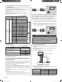
8.2. Setting the DIP switches
Set the remote controller DIP switches.
[Example]
1
2
3
4
5
6
DIP switch 1
Front case (back side)
OFF ON
ON
(
★
Factory setting)
NO.
SW state
Detail
OFF ON
DIP-
switch 1
SW 1
★
Cannot be used.
(Do not change)
SW 2
★
Dual remote controller setting
* Refer to “DUAL REMOTE
CONTROLLERS” in “10.
SPECIAL INSTALLATION
METHODS”.
SW 3
★
Use prohibited.
(Do not change)
SW 4
★
Use prohibited.
(Do not change)
SW 5
★
Use prohibited.
(Do not change)
SW 6
★
Invalidity
Validity
Memory backup setting
* Set to ON to use batteries
for the memory backup. If
batteries are not used, all
of the settings stored in
memory will be deleted if
there is a power failure.
.
9. CASSETTE GRILLE INSTALLATION
9.1. Remove the intake grille
(1) Slide the 2 grille hooks.
Grille hook
(2) Open the intake grille and remove.

En-14
9.2. Install panel to unit
(1) Install the cassette grille on the indoor unit.
“DRAIN” mark “PIPE” mark
* Align the stamped marks on the cassette grille to the pipe and the
drain of the indoor unit.
Screw
CAUTION
Use only the supplied screws to install the cassette
grille.
Indoor unit
Ceiling
No gap between ceiling and
cassette grille around entire
perimeter
3/16 to 4/16 in.
(5 to 7 mm)
Cassette grille
Sealant
(2) Connect the connector.
Wire (louver): WHITE
Wire (display): WHITE
Wire (louver): RED
Indoor unit side
• Arrange the wires as illustrated.
(3) Attach the connector cover.
Screw
Connector cover
9.3. Attach the intake grille
The installation is the reverse of “8.2. Remove the intake
grille”.
The intake grille can be rotated and installed 4 ways to suit
the user’s preference.
CAUTION
The louver angle cannot be changed if the power is not
on. (If moved by hand, it may be damaged.)
The grille assembly is directionally relative to the air
conditioner body.
Install so that there is no gap between the grille assembly
and the air conditioner body.
The cassette grille is equipped with an accessory to
prevent the grill to completely open. Be sure to read
the Installation manual included with the cassette grille
before installation.
10. FUNCTION SETTING
This procedure changes the function settings used to control
the indoor unit according to the installation conditions. Incor-
rect settings can cause the indoor unit to malfunction. This
procedure should be performed by authorized installation or
service personnel only.
Perform the “Function Setting” according to the installation
conditions using the remote controller. (Refer to the indoor
unit installation manual for details on the function numbers
and setting values.)
(1) Press the SET TEMP. buttons ( ) ( ) and FAN button
simultaneously for more than 5 seconds to enter the func-
tion setting mode.
SU
MO
TU
WE
TH FR
SA

En-15
(2) Press the SET BACK button to select the indoor unit
number.
SU
MO
TU
WE
TH FR
SA
Unit number of INDOOR UNIT
SET BACK
(3) Press the Set time ( ) buttons to select the function
number.
Function number
SU
MO
TU
WE
TH FR
SA
(4) Press the SET TEMP. buttons ( ) ( ) to select the set-
ting value.
The display fl ashes as shown in the following during set-
ting value selection.
Setting value
SU
MO
TU
WE
TH FR
SA
(5) Press the TIMER SET button to confi rm the setting.
Press the TIMER SET button for a few seconds until the
setting value stops fl ashing.
If the setting value display changes or if “- -” is displayed
when the fl ashing stops, the setting value has not been
set correctly.
(An invalid setting value may have been selected for the
indoor unit.)
(6) Repeat steps 2 to 5 to perform additional settings.
Press the SET TEMP. buttons (
) ( ) and FAN button
simultaneously again for more than 5 seconds to cancel
the function setting mode. In addition, the function setting
mode will be automatically canceled after 1 minute if no
operation is performed.
(7) After completing the function setting, be sure to turn off
the power and turn it on again.
• Function Details
(1) Filter sign
Select appropriate intervals for displaying the fi lter sign on the
indoor unit according to the estimated amount of dust in the
air of the room.
If the indication is not required, select "No indication" (03).
(♦... Factory setting)
Function
number
Setting
value
Setting description
11
00 Standard (2500 hours)
01 Long interval (4400 hours)
02 Short interval (1250 hours)
03 No indication ♦
(2) Ceiling height
Select the appropriate ceiling height according to the place of
installation.
(♦... Factory setting)
Function
number
Setting
value
Setting description
20
00 Standard (2.7 m [9 ft]) ♦
01 High ceiling (3.0 m [10 ft])
The ceiling height values are for the 4-way outlet.
Do not change this setting in the 3-way outlet mode.
7000, 9000 Btu/h models cannot be installed in high ceilings.
Do not change this setting.
(3) Outlet directions
Select the appropriate number of outlet directions according
to the installation conditions.
(♦... Factory setting)
Function
number
Setting
value
Setting description
22
00 4-way ♦
01 3-way
(4) Auto restart
Enable or disable automatic restart after a power interruption.
(♦... Factory setting)
Function
number
Setting
value
Setting description
40
00 Enable ♦
01 Disable
* Auto restart is an emergency function such as for power
outage etc. Do not attempt to use this function in normal
operation. Be sure to operate the unit by remote controller or
external device.
(5) Room temperature sensor switching
(Only for Wired remote controller)
When using the Wired remote controller temperature sensor,
change the setting to "Both" (01).
(♦... Factory setting)
Function
number
Setting
value
Setting description
42
00 Indoor unit ♦
01 Both
00: Sensor on the indoor unit is active.
01: Sensors on both indoor unit and wired remote controller
are active.
* Remote controller sensor must be turned on by using the
remote controller

En-16
(6) Remote controller custom code
(Only for wireless remote controller)
The indoor unit custom code can be changed.
Select the appropriate custom code.
(♦... Factory setting)
Function
number
Setting
value
Setting description
44
00 A ♦
01 B
02 C
03 D
(7) External input control
"Operation/Stop" mode or "Forced stop" mode can be selected.
(♦... Factory setting)
Function
number
Setting
value
Setting description
46
00 Operation/Stop mode ♦
01 (Setting prohibited)
02 Forced stop mode
(8) Room temperature sensor switching (Aux.)
To use the temperature sensor on the wired remote controller
only, change the setting to "Wired remote controller" (01). This
function will only work if the function setting 42 is set at "Both"
(01)
(♦... Factory setting)
Function
number
Setting
value
Setting description
48
00 Both ♦
01 Wired remote controller
Setting record
Record any changes to the settings in the following table.
Setting Setting value
(1) Filter sign
(2) Ceiling height
(3) Outlet directions
(4) Auto restart
(5) Room temperature sensor switching
(6) Remote controller custom code
(7) External input control
(8) Room temperature sensor switching (Aux.)
After completing the Function Setting, be sure to turn off the
power and turn it on again.
• Temperature Correction
NOTE:
When changing Function 95, perform this setting before other
Room temp. control settings (Function 30, 31, 92, 93).
If Function 95 is not set first, Room temperature control
settings (Function 30, 31, 92, 93) will be reset and you must
re-do them again.
(1) Heat Insulation condition (building insulation)
Heat insulation conditions differ according to the installed
environment.
Standard insulation "00" allows system to rapidly respond to
the cooling or heating load changes.
High insulation "01" is when the heat insulation structure of
the building is high and does not require system to rapidly
respond to cooling or heating load changes.
When High insulation "01" is selected;
• Overheating (overcooling) is prevented at the start-up.
• All room temp. control settings (Function 30, 31, 92, 93) will
reset to No correction [0.0°F (0.0°C)].
(♦... Factory setting)
Function
number
Setting
value
Setting description
95
00 Standard insulation ♦
01 High insulation
(2) Room temperature control for indoor unit sensor
Depending on the installed environment, correction of the
room temperature sensor may be required.
Select the appropriate control setting according to the installed
environment.
The temperature correction values show the difference from
the Standard setting "00" (manufacturer's recommended
value).
* When Function 95-01(High insulation) is set, the Standard
setting "00" will be the same as No correction "01" [0.0°F
(0.0°C)].
(♦... Factory setting)
Function
number
Setting
value
Setting description
30
(For
cooling)
31
(For
heating)
00 Standard setting* ♦
01 No correction 0.0°F (0.0°C)
02 -1°F (-0.5°C)
More
Cooling
Less
Heating
03 -2°F (-1.0°C)
04 -3°F (-1.5°C)
05 -4°F (-2.0°C)
06 -5°F (-2.5°C)
07 -6°F (-3.0°C)
08 -7°F (-3.5°C)
09 -8°F (-4.0°C)
10 +1°F (+0.5°C)
Less
Cooling
More
Heating
11 +2°F (+1.0°C)
12 +3°F (+1.5°C)
13 +4°F (+2.0°C)
14 +5°F (+2.5°C)
15 +6°F (+3.0°C)
16 +7°F (+3.5°C)
17 +8°F (+4.0°C)
In case of Slim duct type and Floor/Ceiling type models:
In fl oor console installations, select “01”.

En-17
A
F
F
Indoor unit
B. Indoor unit/remote controller sensor setting
The temperature sensor of both the indoor unit and the
remote controller is used to detect the room temperature.
When using this function, the “Room temperature sensor
switching (Function number: 42)” is set at “Both (01)”
(1) Activate the sensor switching function as described in
“Room temperature sensor switching (Function number:
42).”
(2) Press the THERMO SENSOR button for 5 seconds or
more to select the temperature sensor of the indoor unit
or the remote controller.
B
F
F
Indoor unit
11. SPECIAL INSTALLATION METHODS
CAUTION
When setting DIP switches, do not touch any other parts on
the circuit board directly with your bare hands.
Be sure to turn off the main power.
• Dual remote controllers
• 2 separate remote controllers can be used to operate the
indoor units.
•
The timer and self-diagnosis functions cannot be used on
the secondary units.
(1) Wiring method (indoor unit to remote controller)
Remote controller cable
Indoor unit
Remote controller
Secondary unit
Primary unit
(2) Remote controller DIP switch 1 setting
Set SW2 on the remote controller DIP switch 1 according
to the following table.
Number of remote
controllers
Primary unit Secondary unit
SW2 SW2
1 (Normal) OFF –
2 (Dual) OFF ON
(3) Room temperature control for wired remote con-
troller sensor
Depending on the installed environment, correction of the wire
remote temperature sensor may be required.
Select the appropriate control setting according to the installed
environment.
To change this setting, set Function 42 to Both "01".
Ensure that the Thermo Sensor icon is displayed on the
remote controller screen.
(♦... Factory setting)
Function
number
Setting
value
Setting description
92
(For
cooling)
93
(For
heating)
00 No correction 0.0°F (0.0°C) ♦
01 No correction 0.0°F (0.0°C)
02 -1°F (-0.5°C)
More
Cooling
Less
Heating
03 -2°F (-1.0°C)
04 -3°F (-1.5°C)
05 -4°F (-2.0°C)
06 -5°F (-2.5°C)
07 -6°F (-3.0°C)
08 -7°F (-3.5°C)
09 -8°F (-4.0°C)
10 +1°F (+0.5°C)
Less
Cooling
More
Heating
11 +2°F (+1.0°C)
12 +3°F (+1.5°C)
13 +4°F (+2.0°C)
14 +5°F (+2.5°C)
15 +6°F (+3.0°C)
16 +7°F (+3.5°C)
17 +8°F (+4.0°C)
Setting record
Record any changes to the settings in the following table.
Setting Setting value
(1) Heat insulation condition
(building insulation)
(2) Room temperature control for
indoor unit sensor
Cooling
Heating
(3) Room temperature control for
wired remote controller sensor
Cooling
Heating
After completing the Function Setting, be sure to turn off the
power and turn it on again.
SETTING THE ROOM TEMPERATURE DETEC-
TION LOCATION
The location of the sensor detecting the room temperature
can be selected from the following 2 examples. Choose the
best location depending on the installing condition.
Refer to “9.3. Function setting”.
A. Indoor unit sensor setting (factory setting)
The room temperature is detected by the indoor unit tempera-
ture sensor.
When using this function, the “Room temperature sensor
switching
(Function number: 42)” is set at “Indoor unit (00)”
(1) When the THERMO SENSOR button is pressed, the lock
display fl ashes because the function is locked at the factory.

En-18
12. TEST RUN
Check items
(1) Is operation of each button on the remote control unit nor-
mal?
(2) Does each lamp light normally?
(3) Do airfl ow direction louvers operate normally?
(4) Is the drain normal?
(5) Do not have an abnormal noise and vibration during op-
eration?
Do not operate the air conditioner in test run for a long time.
[Operation method]
Depending on your installation, choose from the following:
By the wireless remote controller (with “TEST RUN” button)
• To start test run, press the “START/STOP” button and the
“TEST RUN” button on the remote controller.
• To end test run, press the remote controller “START/STOP”
button.
By the indoor unit or IR receiver unit
• To start test run, press the “MANUAL AUTO” button of the
unit for more than 10 seconds (forced cooling).
• To end test run, press the “MANUAL AUTO” button for more
than 3 seconds or press the remote controller “START/
STOP” button.
By the wired remote controller
• For the operation method, refer to the installation manual
and the operating manual of the wired remote controller.
The Operation indicator lamp and Timer indicator lamp will
simultaneously fl ash during the test run mode.
Heating test run will begin in a few minutes when HEAT is
selected by the remote controller [reverse cycle model only].
13. OPTIONAL KIT INSTALLATION
WARNING
Refer to local codes for acceptable cable type.
This air conditioner can be connected with the following optional kits.
• Fresh air intake kit
• External input/output kit.
CN6
CN103
CN102
Option type Connector No.
Fresh air intake CN6
External input CN102
External output CN103
14. CUSTOMER GUIDANCE
Explain the following to the customer in accordance with the
operating manual:
(1) Starting and stopping method, operation switching, tem-
perature adjustment, timer, air fl ow switching, and other
remote control unit operations.
(2) Air fi lter removal and cleaning, and how to use the air lou-
vers.
(3) Give the operating manual to the customer.
(4) If the wireless remote controller custom code is changed
from A to B, C, or D, it will change back to A when the bat-
teries in the remote controller are replaced. Explain to the
customer how to program the wireless remote controller
for the correct custom code.

En-19
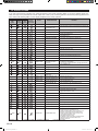
15. ERROR CODES
If you use a wired remote controller, error codes will appear on the remote controller display. If you use a wireless remote con-
troller, the lamp on the photodetector unit will output error codes by way of blinking patterns. See the lamp blinking patterns and
error codes in the following table. An error display is displayed only during operation.
Error display
Wired
remote
controller
Error code
Mode DESCRIPTION Remark
OPERATION
lamp
(green)
TIMER
lamp
(orange)
ECONOMY
lamp
(green)
(1) (1)
Communication
Serial communication error
•
When the indoor unit cannot receive the signal from the branch unit
•
When the branch unit cannot receive the signal from the indoor unit
(1) (2)
Communication
Remote controller
communication error
• Wired remote controller communication error
(1) (5)
Communication
Scan error
•
Check operation incompletion error (normally, operation disabled)
(2) (1)
Function setting
Initial setting error
• Wiring mistake
(2) (2)
Function setting
Indoor unit capacity error
• Indoor unit capacity error
(2) (3)
Function setting
Connection disabled (series error)
• Combination error
(2) (4)
Function setting
Connection unit number
error
• Connection unit number error (indoor unit)
• Connection unit number error (branch unit)
(3) (2)
Indoor unit
Indoor unit main PCB error
• Indoor unit PCB Model information error
(3) (5)
Indoor unit
Manual auto switch error
• Manual auto switch error
(4) (1)
Indoor unit
Room error
• Inlet thermistor error
(4) (2)
Indoor unit
Indoor unit Heat Ex. sensor error
• Indoor unit Heat Ex. Middle thermistor error
(5) (1)
Indoor unit
Indoor unit fan motor 1 error
• Main fan motor lock error
• Main fan motor revolution speed error
(5) (3)
Indoor unit
Water Drain error
• Drain pump error
(5) (15)
Indoor unit
Indoor unit error
• Indoor unit error
(6) (2)
Outdoor unit
Outdoor unit main PCB error
• Outdoor unit PCB Model information error
• Outdoor unit PCB microcomputer communication error
(6) (3)
Outdoor unit
Inverter PCB error
• Inverter error
(6) (4)
Outdoor unit
Active fi lter error, PFC
circuit error
• Voltage error stoppage permanently
• Voltage error (can restore)
• Over current protected operation stoppage permanently
• PFC hardware error
(6) (5)
Outdoor unit
IPM error
• Trip terminal L error
(6) (10)
Outdoor unit
Display panel error
• Microcomputers communication error
(7) (1)
Outdoor unit
Discharge thermistor error
• Discharge thermistor 1 error
(7) (2)
Outdoor unit
Compressor thermistor error
• Compressor thermistor 1 error
(7) (3)
Outdoor unit
Outdoor unit Heat Ex.
Sensor error
• Outdoor unit Heat Ex. liquid thermistor error
(7) (4)
Outdoor unit
Outdoor thermistor error
• Outdoor thermistor error
(7) (5)
Outdoor unit
Suction Gas thermistor error
• Suction Gas thermistor error
(7) (7)
Outdoor unit
Heat sink thermistor error
• Heat sink thermistor error
(8) (2)
Outdoor unit
Sub-cool Heat Ex. gas
thermistor error
• Sub-cool Heat Ex. gas inlet thermistor error
• Sub-cool Heat Ex. gas outlet thermistor error
(8) (3)
Outdoor unit
Liquid pipe thermistor error
• Liquid pipe thermistor 1 error
(8) (4)
Outdoor unit
Current sensor error
• Current sensor 1 error (stoppage permanently)
(8) (6)
Outdoor unit
Pressure sensor error
• Discharge pressure sensor error
• Suction pressure sensor error
• High pressure switch 1 error
(9) (4)
Outdoor unit
Trip detection
• Trip detection
(9) (5)
Outdoor unit
Compressor motor control error
• Rotor position detection error (stoppage permanently)
(9) (7)
Outdoor unit
Outdoor unit fan motor 1 error
• Duty error
(9) (9)
Outdoor unit
4-way valve error
• 4-way valve error
(10) (1)
Refrigerant system
Discharge temperature 1 error
• Discharge temperature 1 error
(10) (3)
Refrigerant system
Compressor temperature error
• Compressor 1 temperature error
(10) (5)
Refrigerant system
Pressure error 2
• Low pressure error
(13) (2)
Branch box
Unit fl ow divider error
• EEPROM access error
• Equipment type information error
• Serial communication error to outdoor unit
• Branch units serial communication error
• Serial communication error to indoor unit
• Liquid pipe thermistor error
• Gas pipe thermistor error
• Expansion valve full closure operation error
• Remote control communication error
• Branch unit error
•
Display mode : 0.5s ON / 0.5s OFF, ( )
: Number of fl ashing, : 0.1s ON / 0.1s OFF
Page is loading ...
-
 1
1
-
 2
2
-
 3
3
-
 4
4
-
 5
5
-
 6
6
-
 7
7
-
 8
8
-
 9
9
-
 10
10
-
 11
11
-
 12
12
-
 13
13
-
 14
14
-
 15
15
-
 16
16
-
 17
17
-
 18
18
-
 19
19
-
 20
20
-
 21
21


Fujitsu AUU18RLF Installation guide
- Category
- Split-system air conditioners
- Type
- Installation guide
Ask a question and I''ll find the answer in the document
Finding information in a document is now easier with AI
Related papers
-
Fujitsu ACUH18LUAS1 Installation guide
-
Fujitsu AUTG54LRLA Installation guide
-
-
Fujitsu ARU36RGLX Installation guide
-
Fujitsu HUG45LRLA Installation guide
-
Fujitsu AUU48RGLX Installation guide
-
-
Fujitsu UTY-RNNUM Installation guide
-
Fujitsu RDG12LLTA Installation guide
-
Fujitsu ARHG72LHTA Installation guide
Other documents
-
 AirStage ARUH60RLAV Installation guide
-
York AFFINITY R-410A User manual
-
Sanyo DHX4852 User manual
-
Sanyo SPW-AS93GH56 Installation guide
-
-
Sanyo C3672R Installation Instructions Manual
-
-
Panasonic CZ-ESWC2 Installation guide
-
-
Hitachi RAM-52QH5 Installation guide
