DuraWater 48k-56sxt-fm Installation guide
- Type
- Installation guide
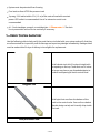
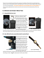
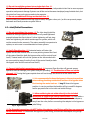
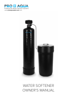
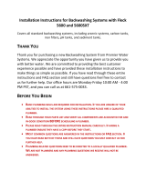
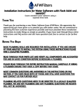
DuraWater 48k-56sxt-fm is an intelligent, fully automated All-in-One filtration system that treats water up to your needs. The installation is simple with the included instructions. The device is capable of eliminating iron and odors from well water, which can greatly improve the quality of your water. DuraWater 48k-56sxt-fm has a compact design, so it won't take up too much space in your home. It requires a 1.5-inch standpipe drain line, is capable of flowing at a rate of 12 gallons per minute, and can be used on water supplies between 20-90 PSI.
DuraWater 48k-56sxt-fm is an intelligent, fully automated All-in-One filtration system that treats water up to your needs. The installation is simple with the included instructions. The device is capable of eliminating iron and odors from well water, which can greatly improve the quality of your water. DuraWater 48k-56sxt-fm has a compact design, so it won't take up too much space in your home. It requires a 1.5-inch standpipe drain line, is capable of flowing at a rate of 12 gallons per minute, and can be used on water supplies between 20-90 PSI.


-
 1
1
-
 2
2
-
 3
3
-
 4
4
-
 5
5
-
 6
6
-
 7
7
-
 8
8
-
 9
9
-
 10
10
-
 11
11
-
 12
12
-
 13
13
-
 14
14
-
 15
15
-
 16
16
-
 17
17
-
 18
18
-
 19
19


DuraWater 48k-56sxt-fm Installation guide
- Type
- Installation guide
DuraWater 48k-56sxt-fm is an intelligent, fully automated All-in-One filtration system that treats water up to your needs. The installation is simple with the included instructions. The device is capable of eliminating iron and odors from well water, which can greatly improve the quality of your water. DuraWater 48k-56sxt-fm has a compact design, so it won't take up too much space in your home. It requires a 1.5-inch standpipe drain line, is capable of flowing at a rate of 12 gallons per minute, and can be used on water supplies between 20-90 PSI.
Ask a question and I''ll find the answer in the document
Finding information in a document is now easier with AI
Other documents
-
GE GFR0728PNDG Dimensions Guide
-
 Premier Water Systems WHSC948RO5 Owner's manual
-
 PRO+AQUA PRO-S-80E User manual
-
 AFWFilters Covers Air Injection Systems Owner's manual
-
Moen T900-001-B3D User manual
-
 Premier Water Systems BWF56FT1054GAC Owner's manual
-
Quality Water For Less FLECK 5800 SXT Installation guide
-
Everbilt THD1069 Operating instructions
-
 AFWFilters WS48-56SXT Installation guide
-
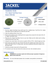 Jackel SFRC18G Installation guide


