Page is loading ...

Planet Dewy
90 A - 110 A
User instructions
GB

VERY IMPORTANT!
PLEASE MAKE SURE YOUR LOG BOOK ENCLOSED IS FILLED IN CORRECTLY.
ALL CORGI REGISTERED INSTALLERS CARRY A CORGI ID CARD.
BOTH SHOULD BE RECORDED IN YOUR CENTRAL HEATING LOG BOOK.
YOU CAN CHECK YOUR INSTALLER IS CORGI REGISTERED
BY CALLING ON 01256 372300

1
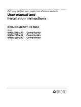
BOILER IGNITION (fig. 1)
Open the gas valve, lower the control
panel cover and activate the boiler by
rotating the selector knob to the summer
position ( ).
The lighting-up of the green
led ( ) will indicate that the apparatus is
switched-on and ready.
–
With the rotary switch in the summer
position ( ) the boiler will start-up upon
demand for domestic hot water, and run
at full power to reach the selected tempe-
rature. The gas feeding pressure will then
automatically vary to ensure that the
required temperature is kept constant.
– With the rotary switch in the winter
position ( ) once the boiler has rea-
ched the value set on the heating poten-
tiometer, it will start to modulate in auto-
matically in order to supply the required
power output to the system.
The operation of the boiler will be stop-
ped through the intervention of the ther-
mostat or “Logica Remote Control”.
TIME-CLOCK INSTRUCTIONS
Setting the time
Turn the clock dial in a clockwise direction
until it reads the time of the day.
Program setting
Press inwards the segments on the pro-
gram disk corresponding to the selected
switching periods.
Function 1: segment set outwards (C.H. “ON”)
Function 2: segment set inwards (C.H. “OFF”)
Manual override
0 = “OFF” permanently
= automatic programmed operation
1 = “ON” permanently
Programming characteristics
Cycle 24 hour
Number of actions per cycle 96
Program time per segment 15 min.
Min. interval between two actions 15 min.
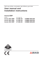
TEMPERATURES ADJUSTMENT (fig. 2)
– The D.H.W. temperature can be adju-
sted by turning the knob of the D.H.W.
potentiometer ( ).
When there is a demand for hot water,
the set temperature is displayed on the
red led scale from 35÷80°C and the yel-
low domestic hot water led lights-up at
the same time ( ).
– The C.H. temperature can be adjusted by
turning the knob of the C.H. potentiome-
ter ( ). The set temperature is indica-
ted on the red led scale from 35÷80°C
and the yellow heating led lights up at the
same time ( ).
To ensure optimal boiler efficiency at all
times, we recommend not to drop below
a minimum working temperature of 50°C.
TURNING OFF BOILER (fig. 1)
To turn off the boiler set the switch to
USER INSTRUCTIONS
WARNINGS
– In case of fault and/or incorrect equipment operation, deactivate it, without making any repairs or taking any direct
action. Contact an authorised technical staff.
– The installation of the boiler and any servicing or maintenance job must be carried out by qualified personnel. Under
no circumstances, the devices sealed by the manufacturer can be tampered with.
– It is absolutely prohibited to block the intake grilles and the aeration opening of the room where the equipment is
installed.
LIGHTING AND OPERATION
REMOTE
CONTROL
R
APRE
SPIA VERDE
Fig. 1
GREEN LED
OPEN

2
“OFF” and close the gas-feeding pipe tap
if the boiler remains inoperative for a long
period
CLEANING AND MAINTENANCE
It is advisable that the boiler is serviced
after 12 months of operation.
Preventative maintenance and
checking of the efficient operation of
the equipment and safety devices must
be carried out by C.O.R.G.I. registered
engineers.
The boiler is supplied with an electric
cable. Should this require replacement,
contact an authorized technical staff.
FAULT FINDING
–
Ignition lock-out
(fig. 3)
If the burners do not ignite, the red led
will light-up
( ).
To attempt a boiler restart, rotate the
selector knob to position
()
and release
it immediately, placing it in the summer
()
or winter
()
operation position
.
If the boiler lock-out re-occurs, contact
an authorised technical staff.
–
Insufficient water pressure
(fig. 4)
If the red "0.5" bar led starts flashing
the boiler will not function, to restart the
operation the system must be rechar-
ged, ask your installer to point out the fil-
ling loop and recharge the system until
the green 1 bar led lights up.
If all the leds are off, call the technical
Help Desk.
SPIA GIALLASPIA ROSSA
Fig. 2
SPIA ROSSA
Fig. 3
Fig. 4
SPIA ROSSA INTERMITTENTE
IN CONDIZIONE DI SICUREZZA
RED LED YELLOW LED
RED LED
FLASHING RED LED IN
SAFETY CONDITION

3
–
Safety thermostat trip
(fig. 5)
If the safety thermostat trips, the red
"35°C" led will start flashing. In order to
attempt a boiler restart, rotate the
selector knob to position ( ) and release
immediately, returning it to the summer
( ) or winter ( ) position.
If the boiler lock-out occurs again, call
authorised technical staff.
–
Other anomalies
(fig. 6)
If one of the red
“40÷80°C”
leds start
flashing, switch-off the boiler and try
again.
After 2 or 3 unsuccessful attempts, do
not try again, call the technical helpdesk.
With selector CR/OFF/EST/INV/
RESET of the "PLANET DEWY 90 A-
110 A " control panel in position ( ) all
the functions are managed by the
"Logica Remote Control" regulator.
The operating instructions are reported
inside the cover (fig. 7).
Each setting or modification is displayed
(fig. 8).
LOGICA REMOTE CONTROL
1
6
7
8
4
5
3
2
KEY
1 Display
2 Info button
3 Operating mode button: automatic operation
4 Operating mode button: manual operation
5 Operating mode button: availability
6 Cover with instruction compartment
7 Temperature knob
8 Presence button
Fig. 7
KEY
1 Display, time
2 Heating programme
3 Unit (%/C°)
4 Presence button display
5 External temperature
6 Ambient temperature
7 Holiday function
8 Operating mode
9 Line number/day
10 Burner on
11 Heating function
12 Domestic hot water/temperature/domestic
hot water load
Fig. 8
SPIA ROSSA INTERMITTENTE
Fig. 5
Fig. 6
SPIA ROSSA INTERMITTENTE
FLASHING RED LED
FLASHING RED LED

4
If your house is too warm or too cold, you can easily correct the set tempe-
rature by adjusting the temperature knob.
Before re-correcting, allow the temperature to stabilise.
Note: The temperature knob can only be used to correct the set temperature, while the redu-
ced temperature remains unaltered.
– Temperature correction
Rotating the knob towards the + sign increases the set tempera-
ture by approximately 1°C per notch.
Rotating the knob towards the – sign decreases the set tempera-
ture by approximately 1°C per notch.
Before correcting the temperature on the regulator, the thermostat valve temperatures
(if provided) must be set to the required temperature first.
Each time the info button is pressed, the fol-
lowing are displayed one after the other. The
temperature sensor continues to function
independently of the display
Day, time, ambient temperature
External temperature *
Domestic hot water temperature *
* This information appears only when the
relative sensor is connected or if it is tran-
smitted by the boiler regulator.
– Info button
(grey reference button)
The required operating mode is selected by
pressing the relative button with the corre-
sponding symbol. The selection is displayed
with the symbol
Automatic operation: the heating functions automatically in line with the set heating
programme. The programme can be switched-off for brief periods by pressing the
presence button.
Manual operation: the heating functions manually in line with the selection of the
presence button.
Availability: heating is deactivated.
– Selection of operating mode
(grey reference buttons)
OPERATION
During operation, the cover of the controller must be kept closed.

5
If the rooms remain unused for long periods of time, you can reduce
the temperature with the presence button, thus saving energy.
When the rooms are occupied, they can be heated by re-pressing the
presence button.
The current selection is shown on the display:
The current selection becomes permanent in manual mode , in automatic mode it
only lasts until the next heating programme switches-in.
– Presence button
Heating to the set temperature
Heating to the reduced temperature
NOTE:
In automatic mode, the apparatus switches between the set temperature and the reduced
temperature according to the timer programme. The switch-over of the temperatures in
manual mode is performed manually with the presence button.
– Temperature control
Set temperature:
Temperature during occupation of the rooms
(basic setting).
Reduced temperature:
Temperature during periods of absence or at night.
Domestic hot water temperature:
Temperature required for domestic hot water.
Before correcting the temperature on the regulator, the thermostat valve temperatures
(if provided) must be set to the required temperature first.
1
2
3
PROGRAMMING
When programming, the regulator panel must be open.
As soon as the cover is opened,
the display and the functions of
the buttons are switched. The
number in the box indicates the
programme line and can be
selected using the arrow but-
tons.
You can set or display the following values:
• Temperature up to
• Heating programme up to
• Day of the week and time up to
• Current values up to
• Holiday length
• Return to default values
1 3
4 11
12 14
15 17
18
19
– Heating/domestic hot
water programme
The heating programme can be used to pre-set the temperature switch-over times for one
week.
The weekly programme consists of 7 daily programmes.
One day programme allows three heating phases to be set-up. Each phase is defined by a start
and finish time.
Day programme n.8 is for domestic hot water (for setting by the heating engineer only).
If one of the phases is not necessary, enter the same start and finish times.

6
– Holiday function
For setting the number of days of absence.
The holiday symbol ( ), will appear on the display, the start day on the left (1 =
Monday / 7 = Sunday) and the number of holiday days on the right.
18
During the holiday period, the regulator will switch to availability mode.
When the set days have passed, the regulator will switch to automatic operation
mode.
NOTE:
The holiday function can be cancelled by pressing one of the operating mode buttons
– Current values
Display and setting of the slope of the characteristic heating curve. Choose a gradient
indicated at point 2.10.3 when the imposed room temperature is not reached.
Display of the current temperature in the boiler.
Display of the current burner power and operating mode ( = heating / =
domestic hot water)
15
16
17
– Setting the time
To set the day of the week
(1 = Monday / 7 = Sunday).
Setting the hour.
Setting the minutes.
The setting of the time will change when a full hour is reached.
12
13
14
The current time is adjusted with and keeping these buttons pressed will accele-
rate the adjustment.
Select the day required for the heating phases (1 = Monday... 7 = Sunday/8 = dome-
stic hot water programme)
Start of phase 1: heating in set mode
End of phase 1: heating in reduced mode
Start of phase 2: heating inset mode
End of phase 2: heating in reduced mode
Start of phase 3: heating inset mode
End of phase 3: heating in reduced mode
Copying a day programme
Press this button to copy the current heating programme to the next day.
Press this button to copy the current heating programme to the previous
day.
The next day is displayed as confirmation.
4
5
6
7
8
9
10
11

7
1
0
– Default value
To return the settings to their default values, press buttons and simul-
taneously for at least 3 seconds. A symbol will appear on the display as confirmation.
19
WARNING
The values in the following lines previously entered will be lost.
• Temperature and time programme up to
• Holiday duration
1 10
18
– Error display
Ignition lock-out
Rotate selector CR/OFF/EST/INV/RESET on the "PLANET DEWY 90 A-110 A" control panel
to the release position
()
to reset operation (fig. 3).
If the lock-out re-occurs, call authorised technical staff.
Safety thermostat trip
Rotate selector CR/OFF/EST/INV/RESET on the "PLANET DEWY 90 A-110 A" control panel
to the release position
()
to reset operation (fig. 5).
If the lock-out re-occurs, call authorised technical staff.
Domestic hot water sensor fault (SS)
Call authorised technical staff.
67
68
69
70
192
193
195
Heating sensor fault (SM)
Call authorised technical staff.
Insufficient water pressure
Reset operation using the boiler charge valve (fig. 4).
Plant overpressure
Call authorised technical staff.
Safety thermostat trips
Call authorised technical staff.
Ventilator
Call authorised technical staff.
No communication between the "Logica Remote Control" and the boiler.
Call authorised technical staff.


Cod. 6274211B - Documentation Dpt.
Sime Ltd
Westbourne House 80 Bagley Lane, Farsley, Leeds, LS28 5LY
Tel. 0870 9911114 - Fax 0870 9911115
www.sime.ltd.uk - e-mail: enquir[email protected]
/