Page is loading ...

1
IMPORTANT:
IMPORTANT:
Go to www.extron.com for the complete
product specications.
PMK 560 • Installation Guide
The Extron PMK 560 Pole Mount Kit, designed for use with the Extron PoleVault™ System, allows for easy mounting of PoleVault
products to a projector pole. It is used to mount the PoleVault system switcher, the associated power supply, and an accessory
device within an enclosure and below a suspended ceiling.
CAUTION: The maximum load for the PMK 560 is 15 lbs (6.8 kg).
ATTENTION : La charge maximum pour le PMK 560 est 6,8 kg (15 lbs).
Items included in the kit are:
• Covers (2)
• Base plate (1)
• Mounting plate (1)
• Tie wraps and pads (to secure power supply)
• 4-40 Screws (to mount devices) (3)
• Cover Screws (4)
NOTE: For full device installation, configuration, menus,
connector wiring, and operation details of the PoleVault
switcher, see the PoleVault System Installation Guide,
available at www.extron.com.
Installation
To install the PMK 560 in a PoleVault system:
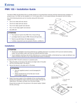
1. Remove the four cover screws from the center of the PMK 560
(see figure 1). Slide the two halves apart and remove them from
the base plate.
NOTE: If the PoleVault switcher and its power supply are
already installed, go directly to step 4.
2. To mount the PoleVault switcher, place the mounting plate,
with the raised tabs upwards, on the top surface of the
switcher and pass the two supplied 4-40 x 3/16 inch screws
into the top of the switcher (see figure 2,
1
). Secure the
mounting plate but do not overtighten.
ATTENTION:
• Use only supplied screws to avoid damaging the
switcher.
• Utilisez seulement les vis fournies pour ne pas
endommager le sélecteur.
3. Attach the associated power supply to the base plate with the
supplied tie wraps and pads, by passing them through the
appropriate slots and around the power supply (
2
).
Tighten until snug.
4. Loosen the four pipe collar set screws (
3
), and slide
the base plate up the pipe until it is touching the suspended
ceiling.
5. Level the base plate and secure it by fully tightening the set
screws.
NOTE: At least three set screws must come in contact
with the pipe.
6. Hook the combined plate and switcher into the PMK 560 base
plate (
4
). Secure it to the base plate with two screws.
PMK Covers (2)
Base Plate
To open, remove 4 cover screws
and slide the covers away.
Mounting Plate
LAN 1
LAN 3
LAN 2 LAN 4
L
R
DO NOT
GROUND
OR SHORT
S
PEAKER
OUTPUTS
4/8
Ω
- - A MAX
POWER
12V
HDMI
HDMI
1/2
SIG
LINK
SIG
LINK
3/4
5
6
INPUTS
OUTPUT
AUDIO OUT
PVS 407D
AMPLIFIED AUDIO OUT
PAGING
SENSOR
PVT IN
PVT IN
L
R
AUX
OVER PVT
REMOTE
VOICELIFT
LAN
INPUT 7
+V
L
R
RS-232
TxRx
IR
S G
G
C
LASS 2 WIRING
LAN
A
ttach mounting plate
to the top of th
e
PoleV
ault switcher.
Hook the combined mounting
plate and switcher into the
base plate and secure with
screws.
Projector
Pole
Attach
Power
Supply
Attach PMK to the pr
ojector
pole pipe collar with the four
10-32 set scr
ews.
PVS 407D
Switcher
1
2
3
4
Figure 1. PMK 560
• figure1
Figure 2. Attach the mounting plate to the switcher
and secure both to the base plate.
1 figure2

2
68-2385-01 Rev. B
11 19
© 2013-2019 Extron Electronics — All rights reserved. www.extron.com
All trademarks mentioned are the property of their respective owners.
Worldwide Headquarters: Extron USA West, 1025 E. Ball Road, Anaheim, CA 92805, 800.633.9876
For information on safety guidelines, regulatory compliances, EMI/EMF compatibility, accessibility, and related topics, see the
Extron Safety and Regulatory Compliance Guide on the Extron website.
7. Route the signal cables so that they exit the pipe via the cable access slot (see figure 3).
WARNING: Do not thread any high voltage power cabling, such as power supply or projector power cords, through the
projector pipe. This violates the National Electrical Code.
AVERTISSEMENT : Ne pas enfiler un câble d’alimentation haute tension, tel qu’un cordon électrique ou un câble de
projecteur, à travers le tube du projecteur. Cet acte est contraire au National Electrical Code (NEC) américain.
8. Attach the cables to the switcher and pull any excess cable back into the ceiling. Feed the output cables to the projector via
the cable access slot to the base of the pipe.
9. Continue installing the projector and other devices, following the directions of the relevant device manufacturer.
10. Slide the covers onto the base plate, passing the AC power cord out through the power cord slot between the covers (see
figure 3).
11. Slide the covers onto the base plate, passing the AC power cord out through the power cord slot between the covers).
Refer to the PoleVault System Installation Guide, available at www.extron.com, to complete the installation and setup.
LAN
1
L
AN 3
L
AN
2
LAN
4
L R
D
O
N
OT
GROUND
O
R SH
O
R
T
SP
EAKER
O
U
TP
U
TS
4
/8
Ω
- - A MAX
POWER
12V
HDMI
HDMI
1/2
SIG LINK SIG LINK
3/4
5
6
INPUTS
OUTPUT
AUD
I
O OUT
PVS 407D
AMPLIFIE
D
AUDIO
OUT
P
AGI
NG
SE
N
SOR
PVT IN
PVT IN
L
R
AUX
O
V
E
R PVT
R
E
MOTE
VOICELIFT
L
AN
INPUT
7
+V
L
R
RS-232
Tx
Rx
IR
S GG
CLAS
S
2 W
I
RI
NG
LAN
PVS 407D
Switcher
Projector
Pole
Cable Access Slot
Cable Slot
Cover
Power Supply
Power Cord Slot
PVS 305SA IP
Switcher
Power Supply
Figure 3. Attach the PMK to the pole, cable the PVS switcher, and then re-attach the
two covers (inset shows the PVS 305SA IP installation location).
2 figure3
/