Page is loading ...

1 L-1821-H
• Assembly
• Installation
• Operation
• Repair Parts
OWNER'S MANUAL
POLY CART, 17 CUBIC FOOT
MODEL:
PCT-17BH
This utility cart is
designed for use with lawn tractors
and lawn and garden tractors.
Important: This manual contains information for the safety
of persons and property. Read it carefully before
assembly and operation of the equipment!
Visit us on the web!
www.brinly.com

2 L-1821-H
================================================================================================
SAFETY LABELS
=================================================
SAFETY LABELS AND NOTATION
This symbol will help to point out important
safety precautions throughout this manual. It
means: ATTENTION! BECOME ALERT! YOUR
SAFETY IS INVOLVED.
The safety labels shown in this section are placed in important
areas on your product to draw attention to potential safety
hazards.
On your product safety labels, the words DANGER, WARNING
and CAUTION are used with the safety-alert symbol. DANGER
identies the most serious hazards.
The operator’s manual also explains any potential safety
hazards whenever necessary in special safety messages that
are identied with the word, CAUTION, and the safety-alert
symbol.
INTRODUCTION AND SAFETY
CUSTOMER RESPONSIBILITIES
- Please read & retain this manual. The instructions will enable to assemble and maintain your product properly.
- Please carefully read and observe the SAFETY SECTION of this manual.
- Follow a regular schedule in maintaining and caring for your Brinly-Hardy product.
CONGRATULATIONS on your new Brinly-Hardy Lawn Cart! This accessory has been designed, engineered and manufactured
to give you the best possible dependability and performance.
Should you experience any problem you cannot easily remedy, please do not hesitate to contact our knowledgeable customer
service department toll-free at 1-877-728-8224. We have competent, well trained technicians to help you with the assembly
and use of your Cart.
English Manual
TABLE OF CONTENTS
INTRODUCTION, REQUIRED
TOOLS, AND SAFETY .......... 2 - 4
PARTS ...................... 5 - 6
ASSEMBLY ................. 7 - 13
OPERATION .................. 14
MAINTENANCE ................ 14
SERVICE ..................... 15
WARRANTY ................... 16
Tools Required for Assembly:
================================================
• 1/2” Wrench (2)
• 9/16” Wrench (2)
• Pliers
• Gloves
SPECIFICATIONS
=================================================
Maximum Towing Speed ............................................. 8 mph
Bed Capacity ........................................................ 17 Cu. Ft.
Maximum Load ......................................................... 850 lbs
Maximum Tongue Weight .......................................... 100 lbs
Empty Weight ........................................................... 107 lbs
Tire; Size ................................................................ 16 x 6.5
Tire; Inflation Pressure .............................................. 28 PSI

3 L-1821-H
================================================================================================
WARNING
AVOID INJURY FROM EXPLOSION
• Do not place gas container in cart when lling
RIDERS CAN FALL OFF AND BE KILLED
• No riders in cart
B-7084
B-6535
TO HELP PREVENT BODILY INJURY DUE TO LOSS OF
STABILITY OR CONTROL
• Do not exceed maximum towing capacity of towing vehicle
listed in the vehicle operator’s manual.
• Do not exceed maximum cart load capacity listed in cart
operator’s manual.
• Reduce loaded cart weight on slopes &/or slippery surfaces.
• Do not exceed 8 mph (13 kph) when towing cart.
CAUTION
ATTENTION
POUR ÉVITER
LES BLESSURES
CAUSÉES PAR
UNE PERTE DE
STABILITÉ OU DE
CONTRÔLE
M151136
● Ne pas dépasser la
capacité de remor-
quage maximum du
véhicule remor-
queur indiquée dans
le livret d’entrentien
du véhicule
● Ne pas dépasser la
capacité de charge
maximum du chariot
indiquée dans le
livret d’entretien du
chariot
● Réduire la charge
du chariot sur les
pentes et/ou les
surfaces glissantes
● Ne pas dépasser
8 mph (13 km/h) lors
du remorquage du
chariot
CAUTION
TO HELP PREVENT
BODILY INJURY
DUE TO LOSS
OF STABILITY
OR CONTROL
• Do not exceed
maximum towing
capacity of towing
vehicle listed in the
vehicle operator’s
manual
●Do not exceed
maximum cart load
capacity listed in
cart operator’s manual
●Reduce loaded cart
weight on slopes
and/or slippery
surfaces
●Do not exceed 8 mph
(13 kph) when towing
cart
SAFETY
English Manual
GENERAL SAFETY NOTES ( Operation )
====================================================== ======================================================
To Help Prevent Bodily Injury Due to a
Loss of Stability or Control
• Do not exceed maximum towing capacity of towing vehicle
listed in the vehicle operator's manual.
• Do not exceed maximum cart load capacity listed in the cart
operator's manual.
• Reduce loaded cart weight on slopes and/or slippery surfaces.
• Do not exceed 8 mph when towing cart.
• Do not tow cart behind a ZTR (Zero Turn Radius) Mower.
• Do not tow cart behind a motor vehicle such as a car, truck,
ATV or UTV.
Safety
• Read the general safety operating precautions in your machine
operator's manual for additional safety information.
Operate Safely
• Use cart for intended purpose only.
• This machine is intended for use in lawn care and home
applications. Do not tow behind a vehicle on a highway or in
any high speed applications. Do not tow at speeds higher than
maximum recommended towing speed.

4 L-1821-H
================================================================================================
Operate Safely ( ...continued )
• Towing speed should always be slow enough to maintain
control. Travel slowly over rough ground.
• Do not let children or an untrained person operate the towing
vehicle or this machine.
• Do not let anyone, especially children, ride on the towing
vehicle, this machine or attachment. Riders are subject to
injury such as being struck by foreign objects and being thrown
off. Riders may also obstruct the operator's view, resulting in
the machine being operated in an unsafe manner.
• Check towing vehicle brake action before you operate. Adjust
or service brakes as necessary.
• Keep all parts in good condition and properly installed. Fix
damage immediately. Replace worn or broken parts. Replace
all worn or damaged safety and instruction decals.
• Do not modify the towing vehicle, this machine or safety devices.
Unauthorized modications to the machine or attachment may
impair its function and safety.
• Securely anchor all loads to prevent loads from falling out
during use.
• Keep all nuts, bolts and screws tight.
• Do not over inate tires.
• Do not restrict operator visibility during use.
• Ensure the operator is at a safe distance when dumping cart!
The Lock Bar that releases the bed has the potential to release
quickly.
• Do not modify hitch/trailer connection on cart.
• Distribute load evenly for safe travel and unloading of cart.
Towing Loads Safely
• Stopping distance increases with speed and weight of towed
load. Travel slowly and allow extra time and distance to stop.
• Total towed weight must not exceed limits specied in towing
vehicle operator's manual.
• Excessive towed load can cause loss of traction and loss of
control on slopes. Reduce towed weight when operating on
slopes.
• Never allow children or others in or on towed equipment.
• Use only approved hitches. Tow only with a machine that has
a hitch designed for towing. Do not attach towed equipment
except at the approved hitch point.
• Follow the manufacturer's recommendations for weight limits
for towed equipment and towing on slopes. Use counterweights
or wheel weights as described in the towing vehicle operator's
manual.
• Do not turn sharply. Use additional caution when turning or
operating under adverse surface conditions. Use care when
reversing. To avoid jack-kning, do not allow towing vehicle
wheels to contact drawbar.
• Do not shift to neutral and coast downhill.
Protect Bystanders
• Keep bystanders away when you operate a towed attachment.
• Before you back machine and attachment, look carefully
behind attachment for bystanders.
• Before you dump cart, look carefully behind attachment for
bystanders.
Keep Riders Off Towed Attachment
• Keep riders off of a towed attachment.
• Riders on a towed attachment are subject to injury, such as
being struck by objects and being thrown off the attachment
during sudden starts, stops and turns.
• Riders obstruct the operator's view, resulting in the attachment
being used in an unsafe manner.
• Keep riders off of hitch bracket.
Keep Body Parts From Under Drawbar. Before you
disconnect this machine from towing vehicle hitch plate:
• Unload cart. Stop on level ground.
• Stop machine engine.
• Lock machine park brake.
• Block attachment wheels.
• Make sure body parts are not under drawbar.
Cart Assembly
When assembling the cart, do the following:
• Do not discard the inner packing sleeve. A template
can be cut from the sleeve to make dividers for the cart.
• Place pieces of carton under the cart bed to avoid scratches.
• Put all bolt heads to the inside of the cart bed.
SAFETY
STOP
Installation Questions?
Missing Parts? Replacement Parts?
DON’T GO BACK TO
THE STORE!
Please call our Customer Service
Department, Toll Free: 877-728-8224
or customerservice@brinly.com
English Manual
GENERAL SAFETY NOTES ( Operation )

5 L-1821-H
================================================================================================
PARTS
English Manual
8
24
12
9
17
24
7
18
19
20
11
19
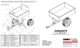
Ref. Description Part Number Qty.
7 Clevis B-3034-10 1
8 Foot Pedal 1008604 1
9 Spring (Foot Pedal) B-3303 1
11 Axle Support Bracket B-3308-10 1
12 Lock Bracket B-3520-10 1
17 Bed 1007473 1
18 Drawbar B-6957-10 1
19 Wheel 1009143 2
20 Axle B-6967 1
24 Longitudinal Support B-8026-10 2
28 Caution Label * B-6535 1
29 Warning Label * B-7084 1
30 Grip Tape * 1008603 1
31 Manual Group * L-1821ASM 1
32 Hardware Pack * Z-1873 1
Contents listed on
the following pg.
- Parts Bag * Z-1873-SUB 1
Contains Parts:
7, 8, 9, 12, 30, 31 & 32
Ref. Description Part Number Qty.
* Not Illustrated

6 L-1821-H
================================================================================================
English Manual
DO NOT RETURN PRODUCT IF YOU ARE MISSING PARTS.
Please Call: 1 (800) 972-6130
HARDWARE IDENTIFIER
Illustrations on this page
are to scale for faster
identication of hardware
during assembly.
Hitch Pin Cotter (x1)
D-146P . . . . . . . . . . . . . . . .
25
Hitch Pin: 1/2" x 2 1/2" (x1) . . . . . . . . . . . . . . . . . . . . . . . . .
13
B-3861
Retaining Ring
3/4” (x2) . . . . . . . . . . . .
14
B-4305
Screw: Round Head
5/16 x 1 1/4”
(x12) . . . . . . . . . . . . .
20M1020P
26
Nut: Hex Head
5/16” (x12) . . . . . . . . . . . . . . . .
4
30M1000P
Nut: Keps
3/8” (x2) . . . . . . . . . . . . . . . . . .
10
B-6299
Nut: Lock
5/16” (x2) . . . . . . . . . . . . . . . . .
22
B-1674P
Nut: Lock
3/8” (x1) . . . . . . . . . . . . . . . . . .
23
B-1675P
Washer: Lock
5/16” (x12) . . . . . . . . . . . . . . . .
5
40M1000P
Washer: Flat
5/16” (x24) . . . . . . . . . . . . . . .
45M1111P
6
Machine Busing
3/4” (x6) . . . . . . . . . .
45M2121P
15
Bolt: Hex Head,
5/16 x 3/4” (x2) . . . . . . . . .
2M1012P
2
Bolt: Hex Head
3/8 x 3 3/4” (x1) . . . . . . . . . . . . . . . . .
3
B-6298
Wheel Spacer
(x2) . . . . . . . . . . . . . . . . .
B-6978-01
21

7 L-1821-H
================================================================================================
x2
26
6
Assembly Step 1
4
6
5
24
17
4
+
5
+
6
6
+
26
x8
26
6
Assembly Step 2
4
6
5
17
11
6
+
26
4
+
5
+
6
ASSEMBLY
2. Secure each support
from inside the cart bed (17)
with one 5/16 x 1 1/4" Round Head
Screw (26), and 5/16" Flat Washer (6).
From the outside, add another 5/16" Flat Washer (6),
one 5/16" Lock Washer (5) and one 5/16" Hex Nut (4), as
shown. Assemble nger tight until all screws are installed.
3. Do NOT tighten nuts (yet).
Install Supports
1. Position the Longitudinal
Supports (24) over the
bed, as shown.
Hardware Panel 1
Install Axle Support
1. Position the Axle Support (11)
over slotted holes over the
Longitudinal Supports (24) and
bed (17).
2. Secure in place from inside the
cart bed (17) with one 5/16 x 1 1/4" Round
Head Screw (26), and 5/16" Flat Washer (6).
From the outside, add another 5/16" Flat Washer
(6), one 5/16" Lock Washer (5) and one 5/16" Hex
Nut (4), as shown. Assemble nger tight until all
screws are installed.
3. Do NOT tighten nuts (yet).
Hardware Panel 2
English Manual

8 L-1821-H
================================================================================================
ASSEMBLY
STARRED EDGE OF THE WASHER NEEDS TO BE FACING THE SPRING.
3
18
Begin to slide the 3/8 x 3-3/4 in. bolt (3)
through the drawbar (18).
Between the drawbar and the latch spring (9),
add one 3/8 in. keps nut (10) to the bolt (3) as illustrated.
NOTE: Foot pedal can be adjusted slightly while installing
bolt (3). This will help to align the bolt with the hole on the
other side of the drawbar.
9
10
8
10
Assembly Step 3
1. Align the cart foot pedal (8) through slot in drawbar (18)
with the notch in the foot pedal oriented towards the raised
tongue on the drawbar. See illustration.
2. While holding the foot pedal (8) in place, ip the drawbar
(18) over.
8
18
9
18
8
Assembly Step 4-A
Squeeze in the latch spring (9) arms and slide in place, as
illustrated. ALIGNMENT NOTES:
• The widest portion of the spring will straddle the
larger of the two drawbar (18) openings.
• The loop of the spring is slightly raised away from the
drawbar and aligns with base of the foot pedal (8).
• Narrow end of the spring rests against the drawbar (18).
Assembly Step 4-B
Hardware Panel 3
English Manual

9 L-1821-H
================================================================================================
ASSEMBLY
3
23
9
1. On the outside of the drawbar, add bolt (3) with a 3/8 in.
hex head locking nut (23) so that the foot pedal moves
forward and backward freely.
2. Tighten nuts (10) toward the spring, but allow movement.
Assembly Step 4-D
1. Pull the arms of the latch spring (9) up
and over the edges of the drawbar (18),
as shown.
Assembly Step 4-E
18
10
10
STARRED EDGE OF THE WASHER NEEDS TO BE FACING THE SPRING.
3
9
10
8
18
10
Assembly Step 4-C
Hardware Panel 3
Hardware Panel 3
Continue to run the bolt (3) through
the latch spring (9), and foot pedal (8).
Between the latch spring (9) and drawbar, add one
3/8 in. keps nut (10) to the bolt (3) as illustrated. Finally, run the
end of the bolt (3) through the other side of the drawbar (18).
NOTE: Foot pedal can be adjusted slightly while installing bolt (3). This will
help to align the bolt with the hole on the other side of the drawbar.
English Manual

10 L-1821-H
================================================================================================
ASSEMBLY
x2
x2
26
6
Assembly Step 5
Assembly Step 6
4
6
5
17
12
4
+
5
+
6
6
+
26
2. Secure the bracket (12)
from inside the cart bed (17) with
one 5/16 x 1 1/4" Round Head Screw (26),
and 5/16" Flat washer (6).
From the outside, add another 5/16" Flat Washer (6),
one 5/16" Lock Washer (5) and one 5/16" Hex Nut (4), as
shown. Assemble nger tight until all screws are installed.
3. Do NOT tighten nuts.
3. Install the clevis pin (13) through clevis and cart drawbar.
Secure with 1/8 in. hairpin cotter (25).
Install Lock Bracket
1. Position the Lock
Bracket (12) over the
bed, as shown.
Hardware Panel 3
Install Clevis
1. Position clevis (7) on the
cart drawbar (18) as illustrated.
2. Slide two 5/16 x 3/4 in. hex head bolts (2)
through the clevis (7) and the drawbar (18).
Secure beneath the drawbar (18) with two
5/16 in. nuts (22).
Hardware Panel 4
18
7
22
2
2
22
25
13
English Manual

11 L-1821-H
================================================================================================
11
20
12
8
Assembly Step 7
11
18
12
Install Drawbar
Add the Drawbar Assembly (18)
in place as shown.
ASSEMBLY
Install Axle
11
18
12
1. Slide the Axle (20) through the
Axle Support (11) as illustrated.
A light coating of grease
or oil will aid in inserting the
Axle (20) though the Axle
Support (11).
Assembly Step 8
2. Verify that the
lock bracket (12)
engages the foot
pedal (8).
NOTE: Adjustment can be made by loosening the two screws that secure
the lock bracket (12) and moving the lock bracket forward or back to change
engagement and / or ease of operation.
12
English Manual

12 L-1821-H
================================================================================================
20
14
ASSEMBLY
Assembly Step 9-B
Assembly Step 9-A
Use pliers to snap retaining ring (14) in to groove on axle (20). Two
extra bushings (15) are also provided in case you need to take up
end play on Axle (20).
NOTE: Wheels come without grease in them!
Use a grease gun to lubricate wheels and axle assembly prior to use.
Pump grease until grease starts coming out around bearing either
inside hub or outside hub.
15
15
15
15
21
21
19
19
Note: Install the wheels so that the grease fitting faces out.
To install wheels, assemble parts
on the axle (20) as follows:
- Wheel Spacer (21)
- Bushing (15)
- Wheel (19)
- Bushing (15)
Hardware Panel 6
Hardware Panel 6
English Manual

13 L-1821-H
================================================================================================
ASSEMBLY
Assembly Step 10
Flip the cart over.
Assembly is Complete!
Operation, Maintenance, and
Service information available on pages 14-15.
Additional info and videos are available on our website ( brinly.com )
OR you can scan this QR code:
English Manual

14 L-1821-H
================================================================================================
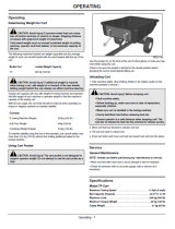
OPERATION AND MAINTENANCE
INSTALLING CART
CAUTION: AVOID INJURY! Before installing
cart, make sure dump lever is locked.
1. Lock cart in place: Lock bracket + foot pedal (8) .
2. Park towing vehicle safely (See Towing Vehicle Manual).
3. Align cart drawbar with towing vehicle drawbar.
4. Install hitch pin (13) through cart drawbar and
towing vehicle hitch. Secure clevis pin with 1/8 in.
spring locking pin.
8
13
REMOVING CART
CAUTION: AVOID INJURY, Before installing
cart, make sure transport latch is facing
toward cart dump lever and dump lever is
locked in place.
NOTE: Refer to illustrations in the Installing Section, earlier in
this manual.
1. Park towing vehicle safely (See Towing Vehicle Manual).
2. Unload cart.
3. Remove cotter pin and drawbar pin.
4. Push cart away from towing vehicle. Block cart wheels.
5. Install drawbar pin and cotter pin in cart drawbar for
storage.
CAUTION: AVOID INJURY! Keep body parts
from under drawbar.
UNLOADING CART
1. Park towing vehicle safely
(See Towing Vehicle Manual).
2. Move lock bar forward to release cart box.
3. Tilt cart bed back to unload cart.
4. Push cart down & move cart lock bar toward cart & lock
into place.
CAUTION: Avoid Injury! Before dumping cart:
Park towing vehicle safely.
Before backing up, make sure area is clear of
bystanders, especially children. Make sure cart is
installed to the towing vehicle. Evenly distribute
load before releasing lock bar.
Ensure the operator is at a safe distance when
dumping cart! The Lock Bar that releases the bed
has the potential to release quickly!
LUBRICATING
WHEEL BEARINGS
1. Lubricate each wheel bearing
with a multipurpose grease or
an equivalent.
2. Wash cart bed after each use to avoid damage to bed or
hardware.
3. Unload cart before performing any maintenance to cart
assembly, including changing flat tires, etc.
English Manual

15 L-1821-H
================================================================================================
The following is the maximum loaded cart weight:
Model Cart Loaded Weight Capacity
17P 850 lbs.
CAUTION: Avoid injury!
If additional weight is required when towing a
cart, add weight at or forward of the rear wheels.
Adding weight behind the rear wheels can affect
machine steering.
SERVICE
DETERMINING WEIGHT FOR CART
QUALITY CONTINUES
WITH QUALITY SERVICE
If you have installation questions, are missing parts or need
replacement parts, don’t go back to the store!
Please find your product serial number and model number,
then contact our Customer Service department:
In North America and Canada call
Toll-Free: 877-728-8224
Chat online: www.brinly.com
Email: customerservice@brinly.com
SERVICE
Additional info and videos
are available on our website
OR scan this QR code:
ONLINE www.brinly.com
PCT-17BH
CAUTION: AVOID INJURY! Excessive towed load can cause loss of traction and loss of control on slopes. Stopping
distance increases with speed and weight of towed load.
Total towed weight must not exceed combined weight of the towing vehicle, ballast and operator.
Cart capacity will vary with weight of towing vehicle and
operator. Add the weight of your towing vehicle to operator
weight to nd the maximum capacity of the cart.
With all cart usage, the cart load should be reduced when
operating on slopes or slippery surfaces to maintain stability.
EXAMPLE: If Towing Vehicle Weighs: 500 lbs.
Add Your Weight: 200 lbs.
Combined weight Equals: 700 lbs.
To maintain stability using the cart in this example, you cannot
safely carry more than 700 lbs. without rst adding additional
ballast to the towing vehicle.
English Manual

16 L-1821-H
The limited warranty set forth below is given by Brinly-Hardy
Company with respect to new merchandise purchased and
used in the United States, its possessions and territories.
Brinly-Hardy Company warrants the products listed below
against defects in material and workmanship, and will at its
option, repair or replace, free of charge, any part found to be
defective in materials or workmanship. This limited warranty
shall only apply if this product has been assembled, operated,
and maintained in accordance with the Owner’s manual furnished
with the product, and has not been subject to misuse, abuse,
commercial use, neglect, accident, improper maintenance,
alteration, vandalism, theft, fire, water, or damage because of
other peril or natural disaster.
Normal Wear Parts or components thereof are subject to
separate terms as follows: All normal wear parts or component
failures will be covered on the product for a period of 90 days.
Parts found to be defective within the warranty period will be
replaced at our expense. Our obligation under this warranty is
expressly limited to the replacement or repair, at our option, of
parts found to be defective in material and workmanship.
HOW TO OBTAIN SERVICE: Warranty parts replacements
are available, ONLY WITH PROOF OF PURCHASE, Through
our Pull Behind Accessories Customer Service Department. Call
877-728-8224.
This limited warranty does not provide coverage in the following
cases:
a) Routine maintenance items such as lubricants and
filters.
b) Normal deterioration of the exterior finish due to
use or exposure.
c) Transportation and/or labor charges.
d) The warranty does not include commercial and/or
rental use.
No implied warranty, including any implied warranty of
merchantability of fitness for a particular purpose, applies
after the applicable period of express written warranty
above as to the part as identified below. No other express
warranty whether written or oral, except as mentioned
above, given by any person or entity, including a dealer
or retailer, with respect to any product, shall bind Brinly-
Hardy Co. During the period of the warranty, the exclusive
remedy is repair or replacement of the product as set forth
above.
The provisions as set forth in this warranty provide the sole
and exclusive remedy arising from the sale. Brinly-Hardy
Company shall not be liable for incidental or consequential
loss or damage including, without limitation, expenses
incurred for substitute or replacement lawn care services
or for rental expenses to temporarily replace a warranted
product.
Some states do not allow the exclusion or limitation of incidental
or consequential damages, or limitations on how long an implied
warranty lasts, so the above exclusions or limitations may not
apply to you.
During the warranty period, the exclusive remedy is replacement
of the part. In no event shall recovery of any kind be greater that
the amount of the purchase price of the product sold. Alteration
of safety features of the product shall void this warranty. You
assume the risk and liability for loss, damage, or injury to you
and your property and/or to others and their property arising out
of the misuse or inability to use this product.
This limited warranty shall not extend to anyone other than the
original purchaser or to the person for whom it was purchased
as a gift.
HOW STATE LAW RELATES TO THIS WARRANTY: This
limited warranty gives you specific legal rights, and you may
also have other rights which vary from state to state.
IMPORTANT: The Warranty period stated below begins with
the PROOF OF PURCHASE. Without the proof of purchase,
the Warranty period begins from the date of manufacture
determined by the serial number manufacturing date.
CART WARRANTY PERIOD:
The warranty period for this lawn cart is as follows: Steel Frame
Parts – 2 Years. Poly Bed – 2 Years. Tires and Wheels are
normal wear parts - 90 days.
MANUFACTURER’S LIMITED WARRANTY FOR
BRINLY PULL-BEHIND ACCESSORIES
Brinly-Hardy Company • 3230 Industrial Parkway • Jeffersonville, IN 47130 • (877) 728-8224
English Manual
/