Page is loading ...

OMM156786 K8
JOHN DEERE
WORLDWIDE COMMERCIAL & CONSUMER
EQUIPMENT DIVISION
OMM156786 K8
All information, illustrations and
specifications in this manual are based on
the latest information at the time of
publication. The right is reserved to make
changes at any time without notice.
COPYRIGHT© 2008
Deere & Co.
John Deere Worldwide Commercial and
Consumer Equipment Division
All rights reserved
Previous Editions
COPYRIGHT© 2006
M1567 86
K8
Utility Cart
17P
OPERATOR’S MANUAL
North American Version
Litho in U.S.A.

Product Identification - 1
PRODUCT IDENTIFICATION
Product Identification
Product Compatibility
This utility cart is designed for use with lawn tractors and lawn and garden
tractors.
Record Purchase Information
Record your purchase information in the spaces provided below.
DATE OF PURCHASE:
_________________________________________
DEALER NAME:
_________________________________________
DEALER PHONE:
_________________________________________
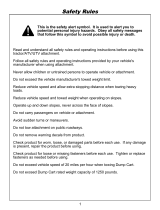
Safety Labels
Understanding The Machine Safety Labels
The machine safety labels shown in this section are placed
in important areas on your machine to draw attention to
potential safety hazards.
On your machine safety labels, the words DANGER,
WARNING, and CAUTION are used with this safety-alert symbol.
DANGER identifies the most serious hazards.
The operator’s manual also explains any potential safety hazards
whenever necessary in special safety messages that are identified with
the word, CAUTION, and the safety-alert symbol.
CAUTION
B7086B
TO HELP PREVENT BODILY INJURY OR EQUIPMENT DAMAGE
• Read owners’ manual
• Use only with lawn and garden tractors
• Do not ride in cart
• Do not exceed 8 mph
• Do not exceed towing capacity listed in the vehicle manual.
• Reduce load on slopes and slippery areas.

Safety - 2
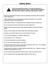
SAFETY
WARNING
B7084B
AVOID INJURY FROM EXPLOSION
• Do not place gas container in cart when filling
RIDERS CAN FALL OFF AND BE KILLED
• No riders in cart
Safety
Read Safety in Machine Operator’s Manual
Read the general safety operating precautions in your machine operator’s
manual for additional safety information.
Operate Safely
• This attachment is intended for use in lawn care and home applications.
Do not tow behind a vehicle on a highway or in any high speed application.
Do not tow at speeds higher than maximum recommended towing speed.
• Towing speed should always be slow enough to maintain control. Travel
slowly over rough ground.
• Do not let children or an untrained person operate machine.
• Do not let anyone, especially children, ride on machine or attachment.
Riders are subject to injury such as being struck by foreign objects and
being thrown off. Riders may also obstruct the operator’s view, resulting in
the machine being operated in an unsafe manner.
• Check machine brake action before you operate. Adjust or service
brakes as necessary.
• Keep all nuts and bolts tight to be sure the equipment is in safe working
condition.
• Keep all parts in good condition and properly installed. Fix damage
immediately. Replace worn or broken parts. Replace all worn or damaged
safety and instruction decals.
• Do not modify machine or safety devices. Unauthorized modifications to
the machine or attachment may impair its function and safety.
• Securely anchor all loads to prevent loads from falling.
• Distribute load evenly for safe travel and unloading of cart.
• Do not obstruct the operator’s view during use.
Towing Loads Safely
• Stopping distance increases with speed and weight of towed load. Travel
slowly and allow extra time and distance to stop.
• Total towed weight must not exceed limits specified in towing vehicle
operator’s manual.
• Excessive towed load can cause loss of traction and loss of control on
slopes. Reduce towed weight when operating on slopes.
• Never allow children or others in or on towed equipment.
• Use only approved hitches. Tow only with a machine that has a hitch
designed for towing. Do not attach towed equipment except at the
approved hitch point.
• Follow the manufacturer’s recommendations for weight limits for towed
equipment and towing on slopes. Use counterweights or wheel weights as
described in the machine operator’s manual.
• Do not turn sharply. Use additional caution when turning or operating
under adverse surface conditions. Use care when reversing.
• Do not shift to neutral and coast downhill.
Protect Bystanders
• Keep bystanders away when you operate a towed attachment.
• Before you back machine and attachment, look carefully behind
attachment for bystanders.
Keep Riders Off Towed Attachment
Keep riders off of a towed attachment.
Riders on a towed attachment are subject to injury, such as being struck
by objects and being thrown off the attachment during sudden starts,
stops and turns.
Riders obstruct the operator's view, resulting in the attachment being used
in an unsafe manner.
Keep riders off of hitch bracket.
Avoid Injury From Drawbar
Before you disconnect an attachment from machine hitch plate:
• Unload attachment.
• Stop attachment on level ground.
• Stop machine engine.
• Lock machine park brake.
• Block attachment wheels.
• Make sure hands, feet or other body parts are not under drawbar.

Assembly - 3
ASSEMBLY
Assembly
Parts in Kit
MX38815a
Bag of Parts (Hardware)
Parts in Kit (Not Shown)
Tools Required
Tools required for assembly:
• 1/2 in. wrench (2)
• 9/16 in. wrench (2)
• Pliers
• Flat blade screwdriver
A
E
N
B
C
D
F
O
G
H
K
L
M
I
J
Qty. Description
10 Slotted Head Screw, 5/16 x 1-1/4 in. (A)
2 Bolt, 5/16 x 3/4 in. (B)
1 Spring Locking Pin, 1/8 in. (C)
2 Spacer, Wheel (D)
1 Clevis Pin, 1/2 x 2-1/2 in. (E)
6 Bushing, 3/4 in. (F)
2 Nut, w/Star Washer, 3/8 in. (G)
1 Locknut, 3/8 in. (H)
2 Locknut, 5/16 in. (I)
10 Lockwasher, 5/16 in. (J)
2 Retaining Ring, 3/4 in. (K)
20 Washer, Flat, 5/16 in. (L)
10 Nut, 5/16 in. (M)
1 Spring, Latch (N)
1 Bolt, 3/8 x 3-3/4 in. (O)
Qty. Description
1Cart
2 Support, Longitudinal
1Lock Bracket
1 Axle Support
1Axle
2Wheel
1Drawbar
1Lock Bar
1Clevis

Assembly - 4
ASSEMBLY
Assemble Cart
When assembling cart, do the following
• Do not discard cardboard bed divider, it can be used as a template for
making dividers for the cart.
• Place pieces of carton under cart box to help avoid scratching finish.
• Put all bolt heads to the inside of the cart box.
Install Supports
MX41739
1. Place the longitudinal supports (A) over the bottom of the cart (B).
2. Secure supports with two 5/16 x 1-1/4 in. slotted head screws (D), four
5/16 in. flat washers (E), two 5/16 in. lock washers (F), and two 5/16 in.
nuts (G). Assemble hardware finger tight until both screws are installed.
Do not tighten nuts at this time.
Install Axle Support
MX41738
1. Place axle support (A) onto slotted holes in longitudinal supports (B) on
bottom of cart (C).
2. Install eight 5/16 x 1-1/4 in. slotted head screws (D) and eight 5/16 in.
flat washers (E), from inside cart box through axle support. Place eight
additional 5/16 in. flat washers (E), eight 5/16 in. lockwashers (F) and
eight 5/16 in. nuts (G) on screws. Assemble hardware finger tight until all
eight screws are installed.
3. Tighten all fasteners for longitudinal supports (B) and axle support (A).
Install Lock Bracket
NOTE: Make sure notch on lock bracket is facing to the front of the
cart.
MX41737
1. Place lock bracket (A) the cart.
2. Install two 5/16 x 1-1/4 in. slotted head screws (B) and two 5/16 in. flat
washers (C) through cart box (from inside cart box) and lock bracket.
NOTE: Lock bracket has slots in it to adjust forward or backward.
3. Secure with two additional 5/16 in. flat washers (C), two 5/16 in.
lockwashers (D) and two 5/16 in. nuts (E). Tighten securely.
A
B
G
F
E
E
D
A
D
E
G
F
E
G
F
E B
B
C
A
B
C
C
E
C
D
C
D
E

Assembly - 5
ASSEMBLY
Assemble Cart Lock Bar
MX38819
Picture Note: Bottom of drawbar shown. Right graphic shows
assembled view.
1. Place cart lock bar (A) through slot in drawbar (B) with notch (C) in lock
bar to rear of cart.
NOTE: Nuts with attached star washers should be installed on each
side of the cart lock bar so it is centered.
Pull up on lock bar while installing bolt. This will help to align the
bolt with the hole on the other side of the drawbar.
2. Install one 3/8 x 3-3/4 in. bolt (D) and one 3/8 in. nut with attached star
washer (E), latch spring (F), and a second 3/8 in. nut with attached star
washer (E) through drawbar and lock bar.
3. With lock bar centered, and ends of spring on brackets of drawbar, as
shown, tighten nuts securely.
4. Secure bolt with 3/8 in. locknut (G) so lock bar moves forward and
backward freely.
Install Clevis
MX38820
1. Install clevis (A) onto cart drawbar (B) with 1/2 x 2-1/2 in. clevis pin (C)
and 1/8 in. spring locking pin (D).
2. Install two 5/16 x 3/4 in. bolts (E) through clevis and cart drawbar, and
fasten with two 5/16 in. locknuts (F).
3. Tighten locknuts.
Install Cart Drawbar and Axle
MX38821
1. Place drawbar (A) onto axle support (B) and lock bracket (C).
NOTE: A light coating of grease or oil on axle will aid in inserting the
axle through the axle support.
2. Slide axle (D) through axle support and drawbar.
3. Verify that the lock bracket (C) engages the lock bar (E). Adjustment
can be made by loosening the two slotted head screws that secure the
lock bracket, and moving the lock bracket forward or rearward to change
engagement or ease of operation.
B
A
G
D
E
E
F
C
A
C
E
F
B
D
F
C
E
A
D
B

Installing - 6
INSTALLING
Install Wheels
NOTE: Two extra 3/4 in. bushings are provided to take up any extra
space on axle.
MX38822
1. Slide one wheel spacer (A) and one 3/4 in. bushing (B) on both axle (C)
ends.
NOTE: Put a small amount of grease on each end of axle, before
installing wheels. This will make installing wheels on axle easier.
2. Put one wheel (D) (valve stem to the outside) on axle.
NOTE: Use a pliers to snap retaining ring into groove on axle.
3. Put second 3/4 in. bushing (B) and one retaining ring (E) on axle.
4. Repeat steps for other wheel.
5. Inflate tires to correct tire pressure.
6. Grease wheel bearings with John Deere multipurpose grease or an
equivalent.
Installing
Installing Cart
MX36820
1. Lock cart lock bar (A) in place.
2. Park machine safely. (See Parking Safely in the Safety section.)
3. Align cart drawbar with machine drawbar.
4. Install clevis pin (B) through cart drawbar and machine drawbar. Secure
clevis pin with 1/8 in. spring locking pin.
Removing
Removing Cart
NOTE: Refer to illustrations in the Installing Section, earlier in this
manual.
1. Park machine safely. (See Parking Safely in the Safety section.)
2. Unload cart.
3. Remove spring locking pin and clevis pin.
4. Push cart away from machine. Block cart wheels.
5. Install clevis pin and spring locking pin in cart drawbar for storage.
C
E
B
D
C
E
A
c CAUTION: Avoid injury! Before installing cart, make sure
dump lever is locked in place.
c CAUTION: Avoid injury! Before installing cart, make sure
transport latch is facing toward cart dump lever and dump lever is
locked in place.
c CAUTION: Avoid injury! Keep hands, feet and other body
parts away from under drawbar.
A
B

Operating - 7
OPERATING
Operating
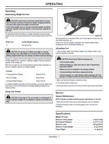
Determining Weight for Cart
The following maximum loaded cart weight capacities are the average
weight of each cart model loaded with dry sand leveled with the top of the
cart.
The amount you can carry in your cart is dependent on two factors:
• the combined weight of the pulling machine, the operator weight, and
potential front ballast,
• as well as the maximum capacity of the cart.
Begin by adding the operator weight to the machine weight. If this total is
less than the maximum cart capacity, you can carry more in the cart by
adding front ballast to the machine. You can continue to add ballast until
you reach the maximum capacity of the cart.
The maximum capacity you carry in this cart cannot be more than the total
of the machine weight, the weight of the operator and any ballast, or the
maximum capacity of the cart.
To maintain stability using the cart in this example, you cannot safely carry
more than 317 kg (700 lb) without first adding additional ballast to the
towing machine.
Unloading Cart
1. Park machine safely. (See Parking Safely in the Safety section.)
2. Move cart lock bar forward to release cart box.
3. Tilt cart box back to unload cart.
4. Push cart down and move cart lock bar toward cart and lock into place.
Service
General Maintenance
NOTE: Unload cart before performing any maintenance or service.
• Lubricate wheel bearings annually or more frequently with heavy use.
• Wash cart bed after each use to avoid damage to bed or hardware.
• Check tire pressure with an accurate gauge, add or remove air if
necessary.
Specifications
Model 17P Cart
Maximum Towing Speed . . . . . . . . . . . . . . . . . . . . . . . . 13 kph (8 mph)
Box Capacity (Heaped) . . . . . . . . . . . . . . . . . . . . . . . . 0.48 m
3
(17 cu ft)
Maximum Load. . . . . . . . . . . . . . . . . . . . . . . . . . . . . . . . 453 kg (1000 lb)
Maximum Tongue Weight . . . . . . . . . . . . . . . . . . . . . . . . . 45 kg (100 lb)
Empty Weight . . . . . . . . . . . . . . . . . . . . . . . . . . . . . . . . . . . 47 kg (105 lb)
Tires
Size . . . . . . . . . . . . . . . . . . . . . . . . . . . . . . . . . . . . . . . . . . . . . . 16.00x6.5
Inflation Pressure . . . . . . . . . . . . . . . . . . . . . . . . . . . . . 193 kPa (28 psi)
Getting Quality Service
John Deere Quality Continues with Quality Service
John Deere provides a process to handle your questions or problems,
should they arise, to ensure that product quality continues with quality
parts and service support.
Follow the steps below to get answers to any questions you may have
about your product.
1. Refer to your attachment and machine operator manuals.
2. In North America or Canada, call John Deere Special Services at 1-
866-218-8622 and provide product serial number (if available) and model
number.
c CAUTION: Avoid injury! Excessive towed load can cause
loss of traction and loss of control on slopes. Stopping distance
increases with speed and weight of towed load.
Total towed weight must not exceed combined weight of pulling
machine, operator and front ballast, or the maximum capacity of
the cart.
Model Cart Loaded Weight Capacity
17P 453 kg (1000 lb)
Example:
If Towing Machine Weighs: 226 kg (500 lb)
Add Your Weight: 90 kg (200 lb)
Combined Weight Equals 317 kg (700 lb)
c CAUTION: Avoid injury! Before dumping cart:
• Park machine safely.
• Before backing up, make sure area is clear of bystanders,
especially children.
• Make sure cart is installed to the towing machine.
/