Supermicro C7H61 User manual
- Category
- Server/workstation motherboards
- Type
- User manual
This manual is also suitable for

C7H61
C7H61-L
USER’S MANUAL
Revision 1.0c

Manual Revision 1.0c
Release Date: May 24, 2013
Unless you request and receive written permission from Super Micro Computer, Inc., you may not
copy any part of this document. Information in this document is subject to change without notice.
Other products and companies referred to herein are trademarks or registered trademarks of their
respective companies or mark holders.
Copyright © 2013 by Super Micro Computer, Inc. All rights reserved.
Printed in the United States of America
The information in this User’s Manual has been carefully reviewed and is believed to be accurate.
The vendor assumes no responsibility for any inaccuracies that may be contained in this document,
makes no commitment to update or to keep current the information in this manual, or to notify any
person or organization of the updates. Please Note: For the most up-to-date version of this
manual, please see our web site at www.supermicro.com.
Super Micro Computer, Inc. ("Supermicro") reserves the right to make changes to the product
described in this manual at any time and without notice. This product, including software and docu-
mentation, is the property of Supermicro and/or its licensors, and is supplied only under a license.
Any use or reproduction of this product is not allowed, except as expressly permitted by the terms
of said license.
IN NO EVENT WILL SUPER MICRO COMPUTER, INC. BE LIABLE FOR DIRECT, INDIRECT,
SPECIAL, INCIDENTAL, SPECULATIVE OR CONSEQUENTIAL DAMAGES ARISING FROM THE
USE OR INABILITY TO USE THIS PRODUCT OR DOCUMENTATION, EVEN IF ADVISED OF
THE POSSIBILITY OF SUCH DAMAGES. IN PARTICULAR, SUPER MICRO COMPUTER, INC.
SHALL NOT HAVE LIABILITY FOR ANY HARDWARE, SOFTWARE, OR DATA STORED OR USED
WITH THE PRODUCT, INCLUDING THE COSTS OF REPAIRING, REPLACING, INTEGRATING,
INSTALLING OR RECOVERING SUCH HARDWARE, SOFTWARE, OR DATA.
Any disputes arising between manufacturer and customer shall be governed by the laws of Santa
Clara County in the State of California, USA. The State of California, County of Santa Clara shall
be the exclusive venue for the resolution of any such disputes. Supermicro's total liability for all
claims will not exceed the price paid for the hardware product.
FCC Statement: This equipment has been tested and found to comply with the limits for a Class B
digital device pursuant to Part 15 of the FCC Rules. These limits are designed to provide reason-
able protection against harmful interference in a residential installation. This equipment generates,
uses, and can radiate radio frequency energy and, if not installed and used in accordance with the
manufacturer’s instruction manual, may cause interference with radio communications. However,
there is no guarantee that interference will not occur in a particular installation. If this equipment
does cause harmful interference to radio or television reception, which can be determined by turn-
ing the equipment off and on, you are encouraged to try to correct the interference by one or more
of the following measures:
•Reorient or relocate the receiving antenna.
•Increase the separation between the equipment and the receiver.
•Connect the equipment into an outlet on a circuit different from that to which the
receiver is connected.
•Consult the dealer or an experienced radio/television technician for help.
California Best Management Practices Regulations for Perchlorate Materials: This Perchlorate warn-
ing applies only to products containing CR (Manganese Dioxide) Lithium coin cells. “Perchlorate
Material-special handling may apply. See www.dtsc.ca.gov/hazardouswaste/perchlorate”.
WARNING: Handling of lead solder materials used in this prod-
uct may expose you to lead, a chemical known to the State of
California to cause birth defects and other reproductive harm.

iii
Preface
Preface
This manual is written for system integrators, PC technicians and
knowledgeable PC users. It provides information for the installation and use of the
C7H61 motherboard.
About This Motherboard
The C7H61 supports a single 2nd and 3rd generation Intel® Core™ i7/i5/
i3, Pentium, Celeron desktop processor in an LGA 1155 socket. With the Intel® H61
Express chipset built in, the C7H61 motherboard offers excellent balance of price/
performance for entry level or embedded applications. Please refer to our website
(http://www.supermicro.com/products/) for processor and memory support updates.
This product is intended to be installed and serviced by professional technicians.
Manual Organization
Chapter 1describesthefeatures,specicationsandperformanceofthemother-
board, and provides information on the Intel H61 Express chipset.
Chapter 2 provides hardware installation instructions. Read this chapter when in-
stalling the processor, memory modules and other hardware components into the
system. If you encounter any problems, see Chapter 3, which describes trouble-
shooting procedures for video, memory and system setup stored in the CMOS.
Chapter 4 includes an introduction to the BIOS, and provides detailed information
on running the CMOS Setup utility.
Appendix A provides BIOS Error Beep Codes.
Appendix B lists software program installation instructions.
Appendix C contains UEFI BIOS Recovery instructions.

iv
Conventions Used in the Manual:
Special attention should be given to the following symbols for proper installation and
to prevent damage done to the components or injury to yourself:
Danger/Caution: Instructions to be strictly followed to prevent catastrophic sys-
tem failure or to avoid bodily injury
Warning: Critical information to prevent damage to the components or data loss.
Important: Important information given to ensure proper system installation or
to relay safety precautions.
Note: Additional Information given to differentiate various models or pro-
vides information for correct system setup.
C7H61 User’s Manual

v
Contacting Supermicro
Contacting Supermicro
Headquarters
Address: Super Micro Computer, Inc.
980 Rock Ave.
San Jose, CA 95131 U.S.A.
Tel: +1 (408) 503-8000
Fax: +1 (408) 503-8008
Email: [email protected] (General Information)
[email protected] (Technical Support)
Web Site: www.supermicro.com
Europe
Address: Super Micro Computer B.V.
Het Sterrenbeeld 28, 5215 ML
's-Hertogenbosch, The Netherlands
Tel: +31 (0) 73-6400390
Fax: +31 (0) 73-6416525
Email: [email protected] (General Information)
[email protected] (Technical Support)
[email protected] (Customer Support)
Asia-Pacic
Address: Super Micro Computer, Inc.
4F, No. 232-1, Liancheng Rd
Chung Ho Dist., New Taipei City 235
Taiwan
Tel: +886-(2) 8226-3990
Fax: +886-(2) 8226-3991
Web Site: www.supermicro.com.tw
Technical Support:
Email: [email protected]
Tel: +886-(2)-8226-3990

vi
Table of Contents
Preface
About This Motherboard ................................................................................................ iii
Manual Organization .....................................................................................................iii
Conventions Used in the Manual: .................................................................................iv
Contacting Supermicro ...................................................................................................v
Chapter 1
Introduction
1-1 Overview ......................................................................................................... 1-1
Checklist .......................................................................................................... 1-1
Motherboard Features ..................................................................................... 1-7
1-2 Chipset Overview ......................................................................................... 1-10
Intel H61 Express Chipset Features ............................................................. 1-10
1-3 Special Features ............................................................................................1-11
Recovery from AC Power Loss ......................................................................1-11
1-4 PC Health Monitoring .....................................................................................1-11
Fan Status Monitor with Firmware Control ...................................................1-11
Environmental Temperature Control ..............................................................1-11
System Resource Alert ..................................................................................1-11
1-5 ACPI Features ............................................................................................... 1-12
Slow Blinking LED for Suspend-State Indicator ........................................... 1-12
1-6 Power Supply ................................................................................................ 1-12
1-7 Super I/O ....................................................................................................... 1-13
Chapter 2
Installation
2-1 Static-Sensitive Devices .................................................................................. 2-1
Precautions ..................................................................................................... 2-1
Unpacking ....................................................................................................... 2-1
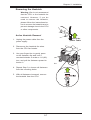
2-2 Processor and Heatsink Installation................................................................ 2-2
Installing the LGA1155 Processor ................................................................. 2-2
Installing an Active CPU Heatsink with Fan ................................................... 2-5
Removing the Heatsink ................................................................................... 2-7
2-3 Installing DDR3 Memory ................................................................................. 2-8
DIMM Installation ............................................................................................ 2-8
Removing Memory Modules ........................................................................... 2-8
Memory Support .............................................................................................. 2-9
C7H61 User’s Manual

vii
Table of Contents
Memory Population Guidelines ....................................................................... 2-9
2-4 Motherboard Installation ................................................................................ 2-10
Tools Needed ................................................................................................ 2-10
Location of Mounting Holes .......................................................................... 2-10
Installing the Motherboard .............................................................................2-11
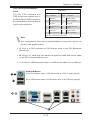
2-5 Connectors/IO Ports ...................................................................................... 2-12
Backplane I/O Panel ..................................................................................... 2-12
ATX PS/2 Keyboard/Mouse Ports ............................................................ 2-13
Universal Serial Bus (USB) ...................................................................... 2-14
Ethernet Ports .......................................................................................... 2-15
BackPanelHighDenitionAudio(HDAudio) ........................................ 2-15
HDMI Port ................................................................................................. 2-16
VGA Port .................................................................................................. 2-16
VESA DisplayPort ..................................................................................... 2-16
Serial Port (COM1) ................................................................................... 2-16
Front Control Panel ....................................................................................... 2-17
FrontControlPanelPinDenitions............................................................... 2-18
Power LED .............................................................................................. 2-18
HDD LED .................................................................................................. 2-18
NIC1/NIC2 (LAN1/LAN2) .......................................................................... 2-19
Overheat (OH)/Fan Fail ............................................................................ 2-19
Reset Button ........................................................................................... 2-20
Power Button ........................................................................................... 2-20
2-6 Connecting Cables ........................................................................................ 2-21
ATX Main PWR & CPU PWR Connectors (JPW1 & JPW2) ................... 2-21
Fan Headers (Fan 1 ~ Fan 4) .................................................................. 2-22
Chassis Intrusion (JL1) ........................................................................... 2-22
Internal Buzzer (SP1) ............................................................................... 2-23
Speaker (JD1) .......................................................................................... 2-23
Onboard Power LED (JLED1) .................................................................. 2-24
Serial Ports (COM1 ~ COM8) .................................................................. 2-24
DOM PWR Connector (JSD1) .................................................................. 2-25
Legacy Wake-On-LAN (JWOL) ................................................................ 2-25
Wake-On-Ring (JWOR) ............................................................................ 2-26
SPDIF IN / SPDIF OUT (JSPDIF_IN/JSPDIF_OUT) ............................... 2-26
TPM Header (JTPM1) .............................................................................. 2-27
Front Accessible Audio Header ................................................................ 2-27
LPT1 Header (PRINTER) ......................................................................... 2-28

viii
2-7 Jumper Settings ............................................................................................ 2-29
Explanation of Jumpers ................................................................................ 2-29
CMOS Clear (JBT1) ................................................................................. 2-30
PCI Slot SMB Enable (JI2C1/C2/C3/C4) ................................................. 2-30
Intel ME Manufacturing Mode (JPME2) ................................................... 2-31
Audio Enable/Disable (JPAC1) ................................................................. 2-31
USB Wake-Up (JUSB1) .......................................................................... 2-32
Watch Dog Timer Reset (JWD1) .............................................................. 2-32
2-8 Onboard Indicators ........................................................................................ 2-33
LAN 1/LAN 2 LEDs .................................................................................. 2-33
Onboard Power LED (LED1) .................................................................. 2-33
2-9 SATA Connections ......................................................................................... 2-34
SATA Connections (I-SATA0~I-SATA5) .................................................... 2-34
Chapter 3
Troubleshooting
3-1 Troubleshooting Procedures ........................................................................... 3-1
Before Power On ............................................................................................ 3-1
No Power ........................................................................................................ 3-1
No Video ......................................................................................................... 3-2
Memory Errors ............................................................................................... 3-2
LosingtheSystem’sSetupConguration ....................................................... 3-2
3-2 Technical Support Procedures ........................................................................ 3-2
3-3 Frequently Asked Questions ........................................................................... 3-3
3-4 Battery Removal and Installation .................................................................... 3-5
Battery Removal .............................................................................................. 3-5
Proper Battery Disposal .................................................................................. 3-5
3-5 Returning Merchandise for Service................................................................. 3-6
Battery Installation ........................................................................................... 3-6
Chapter 4
BIOS
4-1 Introduction ...................................................................................................... 4-1
Starting BIOS Setup Utility .............................................................................. 4-1
HowToChangetheCongurationData ......................................................... 4-1
How to Start the Setup Utility ......................................................................... 4-2
4-2 Main Setup ...................................................................................................... 4-2
System Overview: The following BIOS information will be displayed: ....... 4-3
System Time/System Date ........................................................................ 4-3
C7H61 User’s Manual

ix
Table of Contents
Supermicro C7H61 ..................................................................................... 4-3
BIOS Version .............................................................................................. 4-3
ME Firmware Version ................................................................................. 4-3
Build Date ................................................................................................... 4-3
Processor ................................................................................................... 4-3
Type of Processor ...................................................................................... 4-3
Speed ......................................................................................................... 4-3
Physical Count ........................................................................................... 4-3
Logical Count ............................................................................................. 4-3
System Memory ........................................................................................ 4-3
Size............................................................................................................. 4-3
4-3 AdvancedSetupCongurations...................................................................... 4-4
Boot Feature ................................................................................................. 4-4
Quiet Boot .................................................................................................. 4-4
AddOn ROM Display Mode ........................................................................ 4-4
Bootup Num-Lock ....................................................................................... 4-4
Wait For 'F1' If Error ................................................................................... 4-4
Interrupt 19 Capture ................................................................................... 4-5
PowerConguration ........................................................................................ 4-5
Watch Dog Function ................................................................................... 4-5
Power Button Function ............................................................................... 4-5
Restore on AC Power Loss ........................................................................ 4-5
Resume on RTC Alarm .............................................................................. 4-5
Processor & Clock Options .......................................................................... 4-5
Clock Spread Spectrum ............................................................................ 4-6
Hardware Prefetcher (Available when supported by the CPU) ................. 4-6
Adjacent Cache Line Prefetch (Available when supported by the CPU) ... 4-6
Intel® Virtualization Technology (Available when supported by the CPU) 4-6
Execute-Disable Bit Capability (Available when supported by the OS and
the CPU) ..................................................................................................... 4-6
Intel
®
AES-NI .............................................................................................. 4-6
Intel
®
Hyper Threading Technology (Available when supported by the OS
and the CPU) ............................................................................................. 4-6
Active Processor Cores .............................................................................. 4-7
Power Technology ...................................................................................... 4-7
Turbo Boost Technology (Available when Intel® EIST technology is Enabled)
4-7
Factory Long Duration Power Limit............................................................ 4-7
Long Duration Power Limit ......................................................................... 4-8

x
Factory Long Duration Maintained ............................................................ 4-8
Long Duration Maintained ......................................................................... 4-8
Recommended Short Duration Power Limit ............................................... 4-8
Short duration power limit .......................................................................... 4-8
ChipsetConguration ................................................................................... 4-8
SouthBridgeConguration ........................................................................ 4-10
IDE/SATAConguration ............................................................................. 4-12
SATA Mode ............................................................................................... 4-12
PCIe/PCI/PnPConguration ..................................................................... 4-13
PCI ROM Priority ...................................................................................... 4-13
PCI Latency Timer .................................................................................... 4-13
Active State Power Management ............................................................. 4-13
PCIe Max Read Request Size ................................................................. 4-13
PCI Slot 1, 2, 3, 4, 5 Option ROM ........................................................... 4-13
PCIe Slot 6 & 7 Option ROM ................................................................... 4-14
Load Onboard LAN1/LAN2 Option ROM ................................................. 4-14
SuperIOConguration ............................................................................. 4-14
Nuvoton LPC I/O - NCT6776F ................................................................. 4-14
Serial Port 1 / Serial Port 2 ...................................................................... 4-14
Serial Port 1 Settings ............................................................................... 4-14
Serial Port 2 Settings ............................................................................... 4-14
PS2 KB/MS Wake up ............................................................................... 4-14
Nuvoton LPC I/O - NCT6106D................................................................. 4-15
Serial Port 3 ............................................................................................. 4-15
Serial Port 3, Settings .............................................................................. 4-15
Serial Port 3/Port 4 Mode ........................................................................ 4-15
Serial Port 4 ............................................................................................. 4-15
Serial Port 4, Settings .............................................................................. 4-15
Serial Port 3/Port 4 Mode ........................................................................ 4-15
Serial Port 5 ............................................................................................. 4-16
Serial Port 5, Settings .............................................................................. 4-16
Serial Port 6 ............................................................................................. 4-16
Serial Port 6, Settings .............................................................................. 4-16
Serial Port 7 ............................................................................................. 4-16
Serial Port 7, Settings .............................................................................. 4-16
Serial Port 8 ............................................................................................. 4-17
Serial Port 8, Settings .............................................................................. 4-17
Parallel Port .............................................................................................. 4-17
C7H61 User’s Manual

xi
Parallel Port Settings ................................................................................ 4-17
Parallel Port Mode .................................................................................... 4-17
HardwareHealthConguration .................................................................. 4-18
Fan Speed Control Mode ......................................................................... 4-18
CPU Temperature ..................................................................................... 4-18
System Temperature / Peripheral Temperature ....................................... 4-19
Fan 1 ~ Fan 4 Speed ............................................................................... 4-19
VCORE, 12V, VDIMM, 5VCC, VTT_CPU, AVCC, 3.3VCC, VSB, VBAT . 4-19
ACPIConguration ..................................................................................... 4-20
High Precision Event Timers .................................................................... 4-20
Suspend Mode ......................................................................................... 4-20
Trusted Computing ..................................................................................... 4-20
TrustedComputingConguration ............................................................ 4-20
4-3 Security Settings ........................................................................................... 4-21
Administrator Password .......................................................................... 4-21
User Password: ........................................................................................ 4-21
Boot Sector Virus Protection .................................................................... 4-21
4-4 Boot Settings ................................................................................................ 4-22
Setup Prompt Timeout ............................................................................. 4-22
Boot Options Priority .................................................................................. 4-22
Boot Option #1, Boot option #2, Boot Option #3, etc .............................. 4-22
Network Devices, Hard Disk Drives ......................................................... 4-22
Add New Boot Option ................................................................................... 4-22
Delete Boot Option ..................................................................................... 4-22
4-5 Exit Options ................................................................................................... 4-23
Save Changes and Exit ........................................................................... 4-23
Discard Changes and Exit ...................................................................... 4-23
Discard Changes ...................................................................................... 4-23
Restore Defaults ....................................................................................... 4-23
Save As User Defaults ............................................................................. 4-24
Restore User Defaults .............................................................................. 4-24
Boot Override ........................................................................................... 4-24
Table of Contents

xii
LaunchEFIShellfromlesystemdevice ................................................. 4-24
Reset System with ME disabled Mode ................................................................. 4-24
Appendix A
BIOS Error Beep Codes
A-1 BIOS Error Beep Codes .................................................................................A-1
Appendix B
Software Installation Instructions
B-1 Installing Drivers ..............................................................................................B-1
B-2 ConguringSuperDoctor
®
III .......................................................................... B-2
Appendix C
UEFI BIOS Recovery Instructions
C-1 An Overview to the UEFI BIOS ......................................................................C-1
C-2 How to Recover the UEFI BIOS Image (-the Main BIOS Block)....................C-1
C-3 To Recover the Boot Sector Using a USB-Attached Device ..........................C-1
C7H61 User’s Manual

Chapter 1: Introduction
1-1
Chapter 1
Introduction
1-1 Overview
Checklist
Congratulations on purchasing your computer motherboard from an acknowledged
leader in the industry. Supermicro boards are designed with the utmost attention to
detail to provide you with the highest standards in quality and performance.
Please check that the following items have all been included with your motherboard.
If anything listed here is damaged or missing, contact your retailer.
The following items are included in the retail box.
•One (1) Supermicro Motherboard
•Six (6) SATA cables
•One (1) I/O shield
•One (1) Quick Reference Guide
Note: For your system to work properly, please follow the links below to
download all necessary drivers/utilities and the user's manual for your
motherboard.
•SMCI product manuals: http://www.supermicro.com/support/manuals/
•Product Drivers and utilities: ftp://ftp.supermicro.com/
Warning: For safety considerations, please refer to the complete list of
safety warnings posted on the Supermicro website at http://www.supermi-
cro.com/about/policies/safety_information.cfm.
If you have any questions, please contact our support team at support@supermicro.
com.

1-2
C7H61 User’s Manual
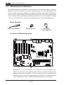
C7H61 Motherboard Image
Note: All graphics shown in this manual were based upon the latest PCB Revision
available at the time of publishing of the manual. The motherboard you've received
may or may not look exactly the same as the graphics shown in this manual.

Chapter 1: Introduction
1-3
C7H61-L Motherboard Image
Note: All graphics shown in this manual were based upon the latest PCB Revision
available at the time of publishing of the manual. The motherboard you've received
may or may not look exactly the same as the graphics shown in this manual.

1-4
C7H61 User’s Manual
JPW2
JPW1
JWOL1
1
3
10
9
1
DIMM1
DIMM3
JF1
1
2
15
Tested to Comply
With FCC Standards
FOR HOME OR OFFICE USE
DESIGNED IN USA
2
J14
1
7
10
J13
1
2
JUSB30
19
11 10
MH10
1
JD1
+
SP1
JSD1
1
JTPM1
2
1
20
19
I-SATA0
1
I-SATA1
I-SATA2
I-SATA3
A-SATA0
A-SATA1
JITP1
60
2
59
1
B1
+
128
1
2
J34
COM2
1
5
6
9
COM5
1
5
COM6
1
5
6
9
COM7
1
5
6
9
COM8
1
5
6
9
1
5
6
COM3
9
1
5
6
COM4
9
BIOS LICENSE
1
JWOR1
JP2
JP1
JSPDIF_OUT
JSPDIF_IN
JI2C3JL1 JI2C4 JBT1
JP3
1
JPME2
JI2C1
1
1
JI2C2
JUSBLAN1
JUSBLAN2
A
LED1
C
LED2
C
A
R474
JPUSB1
1
JWD1
1
JPAC1
JLED1
1
1
JCPUVRD_SMB
FAN4
FAN1
1
FAN3
4
4 1
FAN2
MH6
MH7
JAUDIO1
103
128
64
39
38
2-3:Disable(Default)
1-2:Enable
JPUSB1:USB WAKE UP
2-3:Disable
1-2:RST(Default)
JWD1:Watch Dog
OFF:NORMAL
ON:ME MANUFACTURING MODE
JPME2
VCC
GND
SW
RST
SW
PWR
GND
PWR
LED-
LED-
HDD
LED+
HDD
LED+
PWR
PRINTER
SLOT6 PCI-E 2.0/3.0 X16
SLOT5 PCI 33MHz
SLOT4 PCI 33MHz
SLOT3 PCI 33MHz
OFF:DISABLE
ON:ENABLE
JI2C3/JI2C4:I2C BUS FOR PCI SLOT
AUDIO AC97 AND HD AUDIO JUMPER
USB10/11
USB8/9
USB3.0-0/1
JLED1:
JL1:
3PIN POWER LED
CHASSIS
AUDIO FP
SLOT1 PCI 33MHz
BUZZER
SLOT2 PCI 33MHz
JBT1
JTPM1:TPM/PORT80
CMOS CLEAR
ON:CLEAR
OFF:NORMAL
JWOR:WAKE ON RING
JD1:
SPEAKER:1-4
BUZZER:3-4
JPAC1:ONBOARD AUDIO ENABLE/DISABLE
1-2:ENABLE
2-3:DISABLE
ON:AC'97
JHD_AC1:
OFF:HD AUDIO
SATA DOM PWR
SLOT7 PCI-E 2.0 X1
UNB NON-ECC DDR3 DIMM REQUIRED
HD AUDIO
JWOL:WAKE ON LAN
DIMMA1 DIMMB1
JI2C1/JI2C2:I2C BUS FOR PCI-E SLOT
OFF:DISABLE
ON:ENABLE
RST
ON
PWR
LAN2/
USB4/5
LED
OH/FF
X
LED
HDD
NIC1
NIC2
LED
PWR
USB2/3
LAN1/
HDMI/DP
VGA/COM1
/CPU FAN
INTRUSION
KB/MOUSE & USB0/1
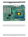
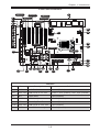
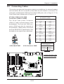
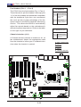
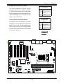
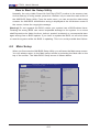
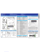
C7H61 Motherboard Layout
Important Notes to the User
•See Chapter 2 for detailed information on jumpers, I/O ports and JF1 front
panel connections.
•" " indicates the location of "Pin 1".
•Jumpers not indicated are for testing only.
•When LED1 (Onboard Standby Power LED Indicator) is on, the system is
plugged in. Unplug the power cable before installing or removing any com-
ponents.
supported on the C7H61 only

Chapter 1: Introduction
1-5
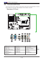
C7H61 Quick Reference
JPW2
JPW1
JWOL1
1
3
10
9
1
DIMM1
DIMM3
JF1
1
2
15
Tested to Comply
With FCC Standards
FOR HOME OR OFFICE USE
DESIGNED IN USA
2
J14
1
7
10
J13
1
2
JUSB30
19
11 10
MH10
1
JD1
+
SP1
JSD1
1
JTPM1
2
1
20
19
I-SATA0
1
I-SATA1
I-SATA2
I-SATA3
A-SATA0
A-SATA1
JITP1
60
2
59
1
B1
+
128
1
2
J34
COM2
1
5
6
9
COM5
1
5
COM6
1
5
6
9
COM7
1
5
6
9
COM8
1
5
6
9
1
5
6
COM3
9
1
5
6
COM4
9
BIOS LICENSE
1
JWOR1
JP2
JP1
JSPDIF_OUT
JSPDIF_IN
JI2C3JL1 JI2C4 JBT1
JP3
1
JPME2
JI2C1
1
1
JI2C2
JUSBLAN1
JUSBLAN2
A
LED1
C
LED2
C
A
R474
JPUSB1
1
JWD1
1
JPAC1
JLED1
1
1
JCPUVRD_SMB
FAN4
FAN1
1
FAN3
4
4 1
FAN2
MH6
MH7
JAUDIO1
103
128
64
39
38
2-3:Disable(Default)
1-2:Enable
JPUSB1:USB WAKE UP
2-3:Disable
1-2:RST(Default)
JWD1:Watch Dog
OFF:NORMAL
ON:ME MANUFACTURING MODE
JPME2
VCC
GND
SW
RST
SW
PWR
GND
PWR
LED-
LED-
HDD
LED+
HDD
LED+
PWR
PRINTER
SLOT6 PCI-E 2.0/3.0 X16
SLOT5 PCI 33MHz
SLOT4 PCI 33MHz
SLOT3 PCI 33MHz
OFF:DISABLE
ON:ENABLE
JI2C3/JI2C4:I2C BUS FOR PCI SLOT
AUDIO AC97 AND HD AUDIO JUMPER
USB10/11
USB8/9
USB3.0-0/1
JLED1:
JL1:
3PIN POWER LED
CHASSIS
AUDIO FP
SLOT1 PCI 33MHz
BUZZER
SLOT2 PCI 33MHz
JBT1
JTPM1:TPM/PORT80
CMOS CLEAR
ON:CLEAR
OFF:NORMAL
JWOR:WAKE ON RING
JD1:
SPEAKER:1-4
BUZZER:3-4
JPAC1:ONBOARD AUDIO ENABLE/DISABLE
1-2:ENABLE
2-3:DISABLE
ON:AC'97
JHD_AC1:
OFF:HD AUDIO
SATA DOM PWR
SLOT7 PCI-E 2.0 X1
UNB NON-ECC DDR3 DIMM REQUIRED
HD AUDIO
JWOL:WAKE ON LAN
DIMMA1 DIMMB1
JI2C1/JI2C2:I2C BUS FOR PCI-E SLOT
OFF:DISABLE
ON:ENABLE
RST
ON
PWR
LAN2/
USB4/5
LED
OH/FF
X
LED
HDD
NIC1
NIC2
LED
PWR
USB2/3
LAN1/
HDMI/DP
VGA/COM1
/CPU FAN
INTRUSION
KB/MOUSE & USB0/1
1
2
DIMMA1
3
4
5
6
7
9
8
12
11
10
13
14
16
15
17 18
21
23
22
24
25
26
27
28
29
31
30
32
33
36
35
34
37
38
39
40
41
44
45
DIMMB1
SLOT5
SLOT6
SLOT7
SLOT3
SLOT2
SLOT1
SLOT4
19
20
Jumpers
# Name Description Default
5 JPAC1 Audio Enable Pins 1-2 (Enabled)
8,10 JI2C3,JI2C4 SMB Header for PCI Slots C7H61-L: Short (Enabled), C7H61: Open (Disabled)
12 JBT1 CMOS Reset Open (Disabled)
13 JPUSB1 USB Wake-Up Pins 2-3 (Disabled)
32 JWD1 Watch Dog Timer Reset Pins 1-2 (Reset)
41,42 JI2C2,JI2C1 SMB Header for PCIE Slots Open (Disabled)
43 JPME2 Intel ME Manufacturing Mode Pins 1-2 (Disabled)
42
43

1-6
C7H61 User’s Manual
Connectors
# Name Description
1 Backpanel I/O See "Connectors/IO Ports", page 1-13
2 AUDIO FP Front Panel Audio Header
3 JWOL Legacy Wake-On-LAN Header
4,14 COM2, COM3~8 COM2 Header, COM3~8 (supported on the C7H61 only)
6,7 S/PDIF OUT, S/PDIF IN S/PDIF OUT/IN Digital Audio Headers
9 JL1 Chassis Intrusion Header
11 JWOR Wake-On-Ring Header
15 USB 3.0 1/0 USB Header 1/0 (3.0) (supported on the C7H61 only)
16,45 USB10/11,8/9 USB 2.0 Header 10/11,8/9
17,20 A-SATA 0,1 (ASMedia) SATA 3.0 Ports (up to 6Gb/s)
18 JTPM1 Trusted Platform Module (TPM) Header
19 JSD1 Disk-On-Module (DOM) Power Header
24,22,23,21 I-SATA 0,1,2,3 (Intel) SATA 2.0 Ports
25 B1 System Battery
26,28,37,39 FAN 3,2,1,4 System FAN Headers 3,2,1 (CPU FAN),4
27 U5 BIOS Chip
29,40 JPW1,JPW2 24-Pin, 4-Pin Aux Power Supply Connectors
31 JF1 Front Panel Control Header
33 JLED1 3-Pin Power LED Header
34 Test Header Reserved for OEM
35 JD1 External Speaker Header (Pins 2-3 shorted for internal buzzer)
36 SP1 Internal Buzzer
38 CPU Socket H2 for an LGA 1155 CPU
44 PRINTER LPT1 Header (supported on the C7H61 only)
LED Indicators
# Name Description Color/State Status
30 LED1 Onboard Standby PWR LED Green: Solid on Standby Power is On

Chapter 1: Introduction
1-7
Notes:
1. CPU Overclocking is supported by this motherboard; however, SMCI does not recommend CPU Overclocking and cannot
resume any responsibility or liability of out_of_spec. overclocking.
2. CATERR_LED is for internal testing only.
Motherboard Features
CPU Single 2nd and 3rd generation Intel® Core™ i7/i5/i3,
Pentium, Celeron desktop processor, LGA 1155 socket
Memory Supports up to 16GB of Unbuffered (UDIMM) non-ECC
DDR3 1600/1333/1066 MHz in 2 memory slots.
Supports dual-channel memory bus
DIMM sizes
UDIMM 1 GB, 2 GB, 4GB, and 8GB
Chipset Intel® H61 Express
Expansion Slots One (1) PCI Express 2.0 x1 slot
One (1) PCI Express 2.0/3.0 x16 slot
Five (5) PCI 33 MHz slots
Network Connections Two (2) Gigabit Ethernet Controllers:
LAN1: Intel 82579V
LAN2: Intel 82574L
Two (2) RJ-45 Rear I/O Panel Connectors with Link and
Activity LEDs
I/O Devices SATA Connections
SATA 3.0 (6Gb/s) Two (2) A-SATA 0~1, via ASMedia
SATA 2.0 (3Gb/s) Four (4) I-SATA 0~3, via Intel H61
USB Devices
Six (6) USB 2.0 ports on the rear I/O panel
All models: Four (4) Front Accessible USB 2.0 ports on
two headers
C7H61 only: Two (2) Front Accessible USB 3.0 ports on
one header
Keyboard/Mouse
One shared PS/2 Keyboard/Mouse port on the I/O
backpanel
Serial (COM) Ports
C7H61: Seven (7) Serial Port headers (COM2~COM8)
C7H61-L: One (1) Serial Port header (COM2)
C7H61: One (1) Serial Port on the back panel (COM1)
Audio
Five (5) Female Mini Jacks for High Denition Audio on
the Back Panel
Front Panel Audio Header
One (1) SP/DIF Optical Out on the back panel
SP/DIF In and SP/DIF Out Headers

1-8
C7H61 User’s Manual
Super I/O
Nuvoton NCT6776F
BIOS 64 Mb AMI BIOS
®
SPI Flash BIOS
Play and Plug (PnP), PCI 3.0, ACPI 4.0, USB Keyboard
and SMBIOS 2.7
Power Conguration ACPI/ACPM Power Management
Main Switch Override Mechanism
Keyboard Wake-up from Soft-Off
Internal/External Modem Ring-On
Wake-On-LAN (WOL) Header
Power-on mode for AC power recovery
PC Health Monitoring CPU Monitoring
Onboard voltage monitors for Vcore, BAT, 3.3V, 3VSB, 5V,
12V, VTT CPU, VDIMM
CPU 3+1 phase switching voltage regulator
CPU/System overheat LED and control
CPU Thermal Trip support
Intel Adaptive Thermal Monitor support
Fan Control
Fan status monitoring with rmware 4-pin (Pulse Width
Modulation) fan speed control
Low noise fan speed control
System Management PECI (Platform Environment Conguration Interface) 3.0
support
System resource alert via SuperDoctor
®
III
SuperDoctor III, Watch Dog
Chassis Intrusion header and detection
CD Utilities BIOS ash upgrade utility
Drivers and software for Intel® H61 Express chipset utili-
ties (available for download)
Other ROHS 6/6 (Full Compliance, Lead Free)
Dimensions ATX form factor (12.0" x 9.6")
Page is loading ...
Page is loading ...
Page is loading ...
Page is loading ...
Page is loading ...
Page is loading ...
Page is loading ...
Page is loading ...
Page is loading ...
Page is loading ...
Page is loading ...
Page is loading ...
Page is loading ...
Page is loading ...
Page is loading ...
Page is loading ...
Page is loading ...
Page is loading ...
Page is loading ...
Page is loading ...
Page is loading ...
Page is loading ...
Page is loading ...
Page is loading ...
Page is loading ...
Page is loading ...
Page is loading ...
Page is loading ...
Page is loading ...
Page is loading ...
Page is loading ...
Page is loading ...
Page is loading ...
Page is loading ...
Page is loading ...
Page is loading ...
Page is loading ...
Page is loading ...
Page is loading ...
Page is loading ...
Page is loading ...
Page is loading ...
Page is loading ...
Page is loading ...
Page is loading ...
Page is loading ...
Page is loading ...
Page is loading ...
Page is loading ...
Page is loading ...
Page is loading ...
Page is loading ...
Page is loading ...
Page is loading ...
Page is loading ...
Page is loading ...
Page is loading ...
Page is loading ...
Page is loading ...
Page is loading ...
Page is loading ...
Page is loading ...
Page is loading ...
Page is loading ...
Page is loading ...
Page is loading ...
Page is loading ...
Page is loading ...
Page is loading ...
Page is loading ...
Page is loading ...
Page is loading ...
Page is loading ...
Page is loading ...
Page is loading ...
Page is loading ...
Page is loading ...
Page is loading ...
Page is loading ...
Page is loading ...
-
 1
1
-
 2
2
-
 3
3
-
 4
4
-
 5
5
-
 6
6
-
 7
7
-
 8
8
-
 9
9
-
 10
10
-
 11
11
-
 12
12
-
 13
13
-
 14
14
-
 15
15
-
 16
16
-
 17
17
-
 18
18
-
 19
19
-
 20
20
-
 21
21
-
 22
22
-
 23
23
-
 24
24
-
 25
25
-
 26
26
-
 27
27
-
 28
28
-
 29
29
-
 30
30
-
 31
31
-
 32
32
-
 33
33
-
 34
34
-
 35
35
-
 36
36
-
 37
37
-
 38
38
-
 39
39
-
 40
40
-
 41
41
-
 42
42
-
 43
43
-
 44
44
-
 45
45
-
 46
46
-
 47
47
-
 48
48
-
 49
49
-
 50
50
-
 51
51
-
 52
52
-
 53
53
-
 54
54
-
 55
55
-
 56
56
-
 57
57
-
 58
58
-
 59
59
-
 60
60
-
 61
61
-
 62
62
-
 63
63
-
 64
64
-
 65
65
-
 66
66
-
 67
67
-
 68
68
-
 69
69
-
 70
70
-
 71
71
-
 72
72
-
 73
73
-
 74
74
-
 75
75
-
 76
76
-
 77
77
-
 78
78
-
 79
79
-
 80
80
-
 81
81
-
 82
82
-
 83
83
-
 84
84
-
 85
85
-
 86
86
-
 87
87
-
 88
88
-
 89
89
-
 90
90
-
 91
91
-
 92
92
-
 93
93
-
 94
94
-
 95
95
-
 96
96
-
 97
97
-
 98
98
-
 99
99
-
 100
100


Supermicro C7H61 User manual
- Category
- Server/workstation motherboards
- Type
- User manual
- This manual is also suitable for
Ask a question and I''ll find the answer in the document
Finding information in a document is now easier with AI
Related papers
-
Supermicro X10SLV-Q User manual
-
Supermicro Supero C7H61-L Quick Reference Manual
-
Supermicro X9SAE User manual
-
-
Supermicro X10SLQ User manual
-
-
-
Supermicro MBD-X9SRA-B User manual
-
-
Other documents
-
SYBA SY-PEX50043 Datasheet
-
DFI KD171 Reference guide
-
Shenzhen Exvist Technology ITS2WB11 User manual
-
 Supero X10SLQ Quick Reference Manual
-
SUPER MICRO Computer X10SLQ User manual
-
 Supero X10SLQ User manual
-
 Supero X9SAE-V User manual
-
BCM BC67Q Quick Start Card
-
Gigabyte GA-3CCWV-RH User manual
-
Renesas PCIe USB 3.0 Controller Card User manual


