Page is loading ...

www.mellanox.com
SwitchX 36 Port FDR IB Switch
Installation Guide
P/N:MSX6025T-1SFR, MSX6025T-1BRR, MSX6025F-1SFR, MSX6025F-1BRR, MSX6036T-1SFR,
MSX6036T-1BRR, MSX6036F-1SFR, MSX6036F-1BRR
Rev 1.5

Document Number: 3489
Rev 1.5
Mellanox Technologies
2
Mellanox Technologies
350 Oakmead Parkway Suite 100
Sunnyvale, CA 94085
U.S.A.
www.mellanox.com
Tel: (408) 970-3400
Fax: (408) 970-3403
Mellanox Technologies, Ltd.
Beit Mellanox
PO Box 586 Yokneam 20692
Israel
www.mellanox.com
Tel: +972 (0)74 723 7200
Fax: +972 (0)4 959 3245
Mellanox®, Mellanox logo, BridgeX®, ConnectX®, CORE-Direct®, InfiniBridge®, InfiniHost®, InfiniScale®, PhyX®,
SwitchX®, Virtual Protocol Interconnect® and Voltaire® are registered trademarks of Mellanox Technologies, Ltd.
Connect-IB™, FabricIT™, MLNX-OS™, ScalableHPC™, Unbreakable-Link™, UFM™ and Unified Fabric Manager™ are
trademarks of Mellanox Technologies, Ltd. All other trademarks are property of their respective owners.
© Copyright 2012. Mellanox Technologies. All Rights Reserved.
NOTE:
THIS HARDWARE, SOFTWARE OR TEST SUITE PRODUCT (“PRODUCT(S)”) AND ITS RELATED
DOCUMENTATION ARE PROVIDED BY MELLANOX TECHNOLOGIES “AS-IS” WITH ALL FAULTS OF ANY
KIND AND SOLELY FOR THE PURPOSE OF AIDING THE CUSTOMER IN TESTING APPLICATIONS THAT USE
THE PRODUCTS IN DESIGNATED SOLUTIONS. THE CUSTOMER'S MANUFACTURING TEST ENVIRONMENT
HAS NOT MET THE STANDARDS SET BY MELLANOX TECHNOLOGIES TO FULLY QUALIFY THE
PRODUCTO(S) AND/OR THE SYSTEM USING IT. THEREFORE, MELLANOX TECHNOLOGIES CANNOT AND
DOES NOT GUARANTEE OR WARRANT THAT THE PRODUCTS WILL OPERATE WITH THE HIGHEST
QUALITY. ANY EXPRESS OR IMPLIED WARRANTIES, INCLUDING, BUT NOT LIMITED TO, THE IMPLIED
WARRANTIES OF MERCHANTABILITY, FITNESS FOR A PARTICULAR PURPOSE AND NONINFRINGEMENT
ARE DISCLAIMED. IN NO EVENT SHALL MELLANOX BE LIABLE TO CUSTOMER OR ANY THIRD PARTIES
FOR ANY DIRECT, INDIRECT, SPECIAL, EXEMPLARY, OR CONSEQUENTIAL DAMAGES OF ANY KIND
(INCLUDING, BUT NOT LIMITED TO, PAYMENT FOR PROCUREMENT OF SUBSTITUTE GOODS OR SERVICES;
LOSS OF USE, DATA, OR PROFITS; OR BUSINESS INTERRUPTION) HOWEVER CAUSED AND ON ANY
THEORY OF LIABILITY, WHETHER IN CONTRACT, STRICT LIABILITY, OR TORT (INCLUDING NEGLIGENCE
OR OTHERWISE) ARISING IN ANY WAY FROM THE USE OF THE PRODUCT(S) AND RELATED
DOCUMENTATION EVEN IF ADVISED OF THE POSSIBILITY OF SUCH DAMAGE.

Switch X SX60XX 36 port FDR Switch Installation Guide
Rev 1.5
Mellanox Technologies
3
Table of Contents
Table of Contents 3
List of Figures 4
Revision History 5
About this Manual 6
Intended Audience 6
Related Documentation 6
Document Conventions 6
Mellanox Part Numbering Legend 8
Chapter 1 Installing the Switch in the Rack 9
1.1 Minimum and Maximum Rack Depth for these Switches. 9
1.2 Rack Mounting 9
1.2.1 Installation Kits 9
1.2.2 Mechanical Installation 10
1.3 Package Contents and Installation 10
1.3.1 Installing the Switch in the Rack 10
1.3.2 Grounding the Switch 15
1.3.3 Power Connections and Initial Power On 16
Chapter 2 Internally Managed Vs. Externally Managed 18
Chapter 3 Configuring the Switch 19
3.1 Introduction 19
3.2 Externally Managed Switches 19
3.3 Managed (Internally Managed) Switches 19
3.3.1 Configuring the Switch for the First Time 19
3.4 Rerunning the Wizard 24
Chapter 4 Connecting to the Switch Platform 25
4.1 Starting an SSH Connection to the Switch (CLI) 25
4.2 Starting a WebUI Connection to the Switch 25
4.3 Resetting the Switch 26
Appendix A Transferring the Power Cord 28
Appendix B QSFP Interface 31
Appendix C RJ45 Console and Ethernet Interfaces 33
Appendix D Replacement Parts Ordering Numbers 34

Rev 1.5
Mellanox Technologies
4
List of Figures
Figure 1: Rack Rail Kit Parts 11
Figure 2: Placement of Switch in Rack 12
Figure 3: Mounting Options 13
Figure 4: Screwing on the Rail 13
Figure 5: Inserting the Caged Nuts 14
Figure 6: Slide the Rail into the Rail Slide 14
Figure 7: Status LEDs 5 Minutes After Power On 15
Figure 8: Two Power Inlets - Electric Caution Notifications 17
Figure 9: Console Port 19
Figure 10: Web UI Login Page 26
Figure 11: Reset Button 26
Figure 12: Transfer Power Cord 28
Figure 13: Install the Switch Slide 29
Figure 14: Transfer Power Cord Finished 30

Switch X SX60XX 36 port FDR Switch Installation Guide
Rev 1.5
Mellanox Technologies
5
Revision History
Table 1 - Revision History of this Installation Guide
Revision Date Details
1.5 September 2012 Reduced the OPNs on the title page to those in the Price book.
1.4 August 2012 Converted Visio graphics to Mechanical drawings
Added figure 2.
1.3 January 2012 Fixed wizards, Added IPv6
1.2 Oct. 2011 Removed clip references from Appendix A.
1.1 July 17, 2011 Replaced the reference to Har 000022. Har 000022 is now in the MTUSB kit
and not packed with the switch.
1.0 July 04, 2011 Initial release

Rev 1.5
Mellanox Technologies
6
About this Manual
This manual describes the installation and set-up instructions of the Mellanox SX60XX switch
family, which is based on the SwitchX IB switch device.
Intended Audience
This manual is intended for users and system administrators responsible for installing and setting
up the switch platform.
The manual assumes familiarity with the InfiniBand
®
architecture specification.
Related Documentation
The documentation set accompanying the SX60XX top of rack switch platform includes the fol-
lowing:
All of these documents can be found on the Mellanox Website. They are available either through
the product pages or through the support page with a login of user and password.
Document Conventions
When discussing memory sizes, MB and MBytes are used in this document to mean size in mega
bytes. The use of Mb or Mbits (small b) indicates size in mega bits.
Table 2 - Reference Documents
Document Name Description
InfiniBand Architecture Specification, Vol. 1,
Release 1.2.1
The InfiniBand Architecture Specification that is provided
by IBTA
Switch Hardware User Manual This document contains HW descriptions, LED assign-
ments and HW specifications among other things.
Mellanox MLNX-OS SwitchX Software
User Manual
This document contains information regarding configuring
and managing Mellanox Technologies’ SwitchX Switch
Platforms.
MLNX-OS Software WebUI User’s Manual WebUI user’s manual for MLNX-OS
MLNX-OS Software Command Reference Guide Command Reference Guide for MLNX-OS listing all of the
commands available through MLNX-OS with explanations
and examples.
MLNX-OS Software Configuration Guide Configuration Guide for MLNX-OS displaying different
configuration scenarios.

Switch X SX60XX 36 port FDR Switch Installation Guide
Rev 1.5
Mellanox Technologies
7
This symbol makes recommendations to the user.
This symbol indicates information that is helpful to the user.
This symbol indicates a situation that can potentially cause damage to hardware or
software.
BEWARE! This symbol indicates a situation that can potentially cause personal injury
or damage to hardware or software.

Rev 1.5
Mellanox Technologies
8
Mellanox Part Numbering Legend
Mellanox Part Numbering Legend
Place Field Decoder
M Mellanox Technologies
SX System Type SwitchX Switch
P Protocol 60 = IB
90 = VPI
MM Port and
Management
Options
25 = 36 Ports externally managed
36 = 36 ports internally managed
C InfiniBand
Port Config
F = FDR, T = FDR10, Q = QDR, D = DDR
- Separator
P # Power Sup-
plies
0=0, 1=1, 2=2....
F Form factor S = standard depth, B = short depth
Y Air Flow
direction
R= Connector side to PSU side airflow
F= PSU side to Connector side airflow
R RoHS R = RoHS6

Switch X SX60XX 36 port FDR Switch Installation Guide
Rev 1.5
Mellanox Technologies
9
1 Installing the Switch in the Rack
1.1 Minimum and Maximum Rack Depth for these Switches.
This switch can be installed in any standard 19” rack with depths of 40cm to 80cm.
Make sure that the Installation kit you have is compatible with your rack.
To use the SwitchX series switch in a rack deeper than 60cm, order the switch with the standard
depth, or order the MSX60-SKIT installation kit. The both of these solutions will allow you to
install the switch in a 19” rack whose vertical supports are between 60cm and 80cm apart.
1.2 Rack Mounting
The switch platform can be rack mounted and is designed for installation in a standard 19” rack.
The power side of the switch includes a hot-swap power supply module, a blank cover for an
optional second PSU for redundancy, and a hot-swap fan tray. There are two possible air flow
directions. Be sure that the switch air flow direction is compatible with your system, rack, and
PSUs. The connector side of the switch has the QSFP ports, system LEDs, and management con
-
nection ports.
The switch platform contains auto-sensing 100 - 240 VAC connections for all possible PSUs.
The installer should use a rack capable of supporting the mechanical and environmental character-
istics of a fully populated platform.
1.2.1 Installation Kits
There are two Installation kit options. One long and one short. Both the standard and the short
switches can be mounted using the long rail kit. The short kit will only work with the short switch.
See “Mellanox Part Numbering Legend” on page 8 for explanation of the switch depth according
to the Model numbers.
The rack mounting holes conform to the EIA-310 standard for 19-inch racks. Take pre-
cautions to guarantee proper ventilation in order to maintain good airflow at ambient
temperature. Cable routing in particular should not impede the air exhaust from the
chassis.
Table 3 - Installation Kit According to Rack Size
Kit OPN Rack Size
MSX60-BKIT 40-60 cm
MSX60-SKIT 60-80 cm

Installing the Switch in the Rack
Rev 1.5
Mellanox Technologies
10
1.2.2 Mechanical Installation
The switch platform can be rack mounted and is designed for installation in a standard 19” rack.
The power side of the switch includes a hot-swap power supply module, a blank cover for an
optional second PS unit for redundancy, and a hot-swap fan tray. There are two possible air flow
directions. Be sure that the switch air flow direction is compatible with your system, rack, and PS
units. The connector side of the switch has the QSFP ports, system LEDs, and management con
-
nection ports.
The switch platform contains auto-sensing 100 - 240 VAC connections for all possible PS units.
The installer should use a rack capable of supporting the mechanical and environmental character-
istics of a fully populated platform.
1.3 Package Contents and Installation
Before you install your new SX6036 switch, unpack the system and check to make sure that all the
parts have been sent, check this against the parts list below. Check the parts for visible damage that
may have occurred during shipping.
The switch comes packed with the following items:
• 1 X – switch
• 1 X – installation kit
• 1 X – power cable for each PS unit – Type C13-C14
See “Replacement Parts Ordering Numbers” on page 34 to order power cords for various
countries.
A single power cord for each power supply unit can be ordered at no extra charge
• 1 X – Harness
HAR000028 – Harness RS232 2M cable – DB9 to RJ-45 for SX6036 switches
• 1 X – Quick Start Guide
• 1 X – China RoHS statement
1.3.1 Installing the Switch in the Rack
Tools and Customer Supplied Parts:
The rack mounting holes conform to the EIA-310 standard for 19-inch racks. Take pre-
cautions to guarantee proper ventilation in order to maintain good airflow at ambient
temperature. Cable routing in particular should not impede the air exhaust from the
chassis.
If anything is damaged or missing, contact your customer representative immediately.
For customer support go to:
www.mellanox.com =>Support => Customer Support Portal Login
• Phillips Screwdrivers #1 and #2 • Grounding screw
• ESD strap • Grounding wire sufficient to reach a valid ground.
• ESD mat

Switch X SX60XX 36 port FDR Switch Installation Guide
Rev 1.5
Mellanox Technologies
11
For racks from 60cm to 80cm deep either use the standard depth switches with the long rail kit or
the short switches with the long rail kit.
Parts included in the rail kit:
Figure 1: Rack Rail Kit Parts
1. Place the ESD mat on the floor where you will be working and put on the ESD strap. Make
sure the ESD strap is touching your skin and that the other end is connected to a verified
ground.
2. Choose which side of the switch you want even with the rack vertical support. Either the side
with the power supply units or the side with the QSFP connectors can be even with one of
the vertical rack supports.
• 2 rails • 16 recessed flat head screws You will have extras!
• 2 rail slides • 10 caged nuts
• 2 switch slides • 10 pan head screws M6
Switch slide x2
Rail x2
Rail slide x2

Installing the Switch in the Rack
Rev 1.5
Mellanox Technologies
12
Figure 2: Placement of Switch in Rack
Things to consider before choosing where to mount the rails and rail slides.
The distance between the rack and the door can be as little as 4 cm on one side of the rack and as
much as 18 cm on the other side of the rack. Keep in mind that there can be as many as 3618 cables
connected to the switch.
Do you want the connector side recessed in the rack to allow for a larger cable bending
radius? It is possible to recess the connector side by 5cm by optional placement of the switch
rails. See
Figure 3,“Mounting Options”.
Will the connector side be recessed past other equipment in the rack and will this be prob-
lematic?
The installation kit allows for a 2” recess of the switch past the vertical support.
1
9
"
(
4
8
2
.
6
m
m
)
Switch
Connector side
Spine side
Cable with
recommended
bending radius
Insufficient room for
recommended bending
radius
Doors
Doors

Switch X SX60XX 36 port FDR Switch Installation Guide
Rev 1.5
Mellanox Technologies
13
Figure 3: Mounting Options
3. Decide which mounting option you want to use.
4. Screw the switch slides onto the switch. Use 5 flat head screws for short switches and 7
screws for standard depth switches, to connect each switch slide.
Figure 4: Screwing on the Rail
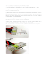
To use the rail kit to transfer the power cord from the connector side to the power side
go now to
“Transferring the Power Cord” on page 28.
5 screws per side are needed for the short switch
7 screws per side are needed for the standard switch
There are 16 screws in the kit; you will have left over screws.

Installing the Switch in the Rack
Rev 1.5
Mellanox Technologies
14
Figure 5: Inserting the Caged Nuts
5. Clip 6 caged nuts into the holes in the rack on the side of the rack you will be sliding the
switch into. Check that both sides of the switch, power side and connector side, are at the
same level in the rack.
6. Clip 4 more caged nuts into the holes on the opposite side of the rack. Check that both sides
of the switch, left and right, are the same level in the rack.
7. Slide the rail into the rail slide.
8. Using two of the bolts for each corner install the rails and rail slides in the rack. Do not
tighten the bolts yet.
Figure 6: Slide the Rail into the Rail Slide
Side you will slide
the switch into
Second side
This side of the rail kit goes on the side of the rack you will
slide the switch into. This is the same side of the switch that
will be next to the vertical support.

Switch X SX60XX 36 port FDR Switch Installation Guide
Rev 1.5
Mellanox Technologies
15
9. Slide the switch into the rails.
10. Tighten the bolts to 9.2 Nm or 81.5 pound inches.
11. Put the switch into place and screw the bolts into the nuts. Tighten the bolts to 9.2 Nm or
81.5 pound inches.
12. Ground the switch.
13. Plug in the power cables.
14. Check the Status LEDs and confirm that all of the LEDs show status lights consistent with
normal operation.
Figure 7: Status LEDs 5 Minutes After Power On
15. You can start connecting all of the cables to the switch.
1.3.2 Grounding the Switch
Check to determine if your local or national electrical codes require an external ground to all IT
components. If so, connect a ground wire to one of the casing screws and connect the other end to
a valid ground. If you choose to not use the ground screw, make sure that the rack is properly
Warning: Any yellow or red status LEDs are cause for concern and must be dealt with
immediately.
It can take up to 5 minutes to boot up, during which time the status LED may indicate
red.
FDR and FDR10 are only guaranteed to work with approved Mellanox Cables.
Caution: Slide/rail mounted equipment is not to be used as a shelf or a work space.

Installing the Switch in the Rack
Rev 1.5
Mellanox Technologies
16
grounded and that there is a valid ground connection between the chassis of the switch and the
rack. Test the ground using an Ohm meter.
1.3.3 Power Connections and Initial Power On
The switch platform ships with one or two Power Supply Units. For switches with only one unit
installed, a second PSU may be installed at a later time. Each supply has a separate AC receptacle.
The input voltage is auto-adjusting for 100 - 240 VAC, 50-60Hz power connections. The power
cords should be standard 3-wire AC power cords including a safety ground and rated for 15A or
higher.
Some national and/or local codes may require IT components to be bonded and exter-
nally grounded (not including the power cord ground). You must follow all national
and local codes when installing this equipment.
Caution: The switch platform will automatically power on when AC power is applied.
There is no power switch. Check all boards, power supplies, and fan tray modules for
proper insertion before plugging in a power cable.
Caution: After inserting a power cable and confirming the green system status LED
light is on; make sure that the Fan Status indicator shows green.
If the fan status indicator is not green then unplug the power connection and check that
the fan module is inserted properly and that the mating connector of the fan unit is free
of any dirt and/or obstacles.
Caution: When turning off the switch, make sure ALL Connector LEDS are off to
ensure a powered down status.

Switch X SX60XX 36 port FDR Switch Installation Guide
Rev 1.5
Mellanox Technologies
17
Figure 8: Two Power Inlets - Electric Caution Notifications
Do not hot swap the power supply if your switch has only one power supply. You must
power down the system to replace the power supply unit when there is only one PSU in
the switch.
CAUTION
Risk of electric shock and energy
hazard. The two PSUs are indepen-
dent.
Disconnect all power supplies to
ensure a powered down state inside
of the switch platform.
ACHTUNG
Gafahr des elektrischen
Schocks. Entferrnen des
Netzsteckers elnes Netzteils
spannungsfrei. Um alle Einhi-
eten spannungsfrei zu machen
sind die Netzstecker aller
Netzteile zu entfernen
ATTENTION
Risque de choc et de danger
e’lectriques. Le de’branchment
d’une seule alimentation stabi-
lise’e ne de’branch uniquement
qu’un module “Alimentation Sta-
bilise’e”. Pour isoler com-
pletement le module en cause, Il
faut de’brancher toutes les alimen-
tations stabilise’es.

Internally Managed Vs. Externally Managed
Rev 1.5
Mellanox Technologies
18
2 Internally Managed Vs. Externally Managed
The following table shows which switches come with a management CPU and which do not.
Externally managed (unmanaged) switches are plug and play out of the box. All switches come
with the latest firmware burned on the flash. Updating the firmware stack for the externally man
-
aged switches is done in-band only. When a new firmware release is available (e-mail notification)
you can upgrade the device through a link to the Mellanox web-page firmware download site.
All internally managed switches have internal chassis management and can support IB fabric of up
to 648 nodes. Internally managed switches need an initial configuration before they will start
working.
Table 4 - Switch Management
Family
Internally/
Externally
Managed
Management Connections
SX6025 Externally
managed
(unmanaged)
Plug and Play
All firmware updates should be done in-band using Mellanox firmware
management tools. I2C port access using MTUSB-1 device is required
for firmware updates if in-band burning is not possible.
SX6036 Internally
managed
RS232 cable DB9 to RJ45 included in the box to connect to host PC for
initial configuration of the switch. After initial configuration the switch
can be managed through the Ethernet port using a remote connection.

Switch X SX60XX 36 port FDR Switch Installation Guide
Rev 1.5
Mellanox Technologies
19
3 Configuring the Switch
3.1 Introduction
The procedures described in this chapter assume that you have already installed and powered-on
your switch according to the instructions in the Switch Installation Guide, this document.
3.2 Externally Managed Switches
Unmanaged (Externally managed) switches, that is the SX6025 switches, do not get configured.
On unmanaged switches, the CONSOLE, Ethernet, and USB connectors are not found do not
work. Instead there is an I2C connector.
The unmanaged switches are Plug and Play and all firmware updates should be done in-band. The
I2C connection should only be used if the firmware image was corrupted to the point that the reg
-
ular firmware tools cannot successfully reburn the correct image.
When you install the switch, it comes with the latest firmware burned on the board. You will not
need to burn firmware unless you get notification from Mellanox that a newer version of firmware
for your switch has been released.
3.3 Managed (Internally Managed) Switches
Internally managed switches must be configured before they will work. Follow the procedures
below to configure the switch.
3.3.1 Configuring the Switch for the First Time
Step 1. Connect the host PC to the Console (RJ-45) port of the switch system using the supplied cable.
The Console ports for SX60XX systems are shown below as examples.
Figure 9: Console Port
36
35
34
CONSOLE
MGT
1
2
SX6036
Connect the host
PC to here.

Configuring the Switch
Rev 1.5
Mellanox Technologies
20
Step 2. Configure a serial terminal program (for example, HyperTerminal, minicom, or Tera Term) on
your host PC with the settings described in
Table 5.
Step 3. Login (from a serial terminal program) as admin and use admin as password. This starts the
Mellanox configuration wizard.
Step 4. Go through the Mellanox configuration wizard. Table 6 shows an example of a wizard session.
Make sure to connect to the Console RJ-45 port of the switch and not to the (Ethernet)
MGT port.
No remote IP connection is available at this stage.
Table 5 - Serial Terminal Program Configuration
Parameter Setting
Baud Rate 9600
Data bits 8
Stop bits 1
Parity None
Flow Control None
Table 6 - Configuration Wizard Session - IP Configuration by DHCP (Sheet 1 of 2)
Wizard Session Display (Example) Comments
Mellanox configuration wizard
Do you want to use the wizard for initial configura-
tion? yes
You must perform this configuration the first time you
operate the switch or after resetting the switch. Type
‘y’ and then press <Enter>.
Step1: Hostname? [switch-1] If you wish to accept the default hostname, then press
<Enter>. Otherwise, type a different hostname and
press <Enter>.
/