Page is loading ...

0
Professional Remote Weather Station
Model WS-2306
Operation Manual

1
Professional Remote Weather Station
Model WS2306
Operation Manual
Table of Contents
Page
1. Introduction………………………………………………. .......2
2. Intended use………………………………………… .............2
Weather Station…………… ...............................................2
System requirements for PC use…………. ........................3
Installation for the USB adaptor driver ...............................3
Features of the base station………… ................................4
Features of the thermo-hygro sensor…………...................4
Features of the wind sensor………….................................5
Features of the rain sensor ................................................5
3. Safety Notes ......................................................................5
4. Packaged contents ............................................................6
5. Setting up...........................................................................7
6. Operation using cable connection or wireless 433MHz .....9
7. LCD overview...................................................................11
8. Function test ....................................................................12
9. Mounting ..........................................................................12
10. Resetting & factory settings .............................................18
11. Function description.........................................................19
12. Operation keys.................................................................21
13. Basic programming modes ..............................................23
14. MIN/MAX programming modes........................................24
15. Alarm programming modes..............................................25
16. Auto-memory for stored values ........................................33
17. Changing batteries...........................................................33
18. Interferences and problems with operation ......................34
19. Transmission range .........................................................35
20. Cleaning and maintenance ..............................................35
21. Specifications...................................................................36
22. Warranty Information .......................................................38

2
This Operation Manual is part of this product and should be kept in a
safe place for future reference. It contains important notes on setup and
operation.
Please see www.heavyweather.info for a complete IM, FAQ and
downloads of the most current software.
1. Introduction
Thank you for purchasing this Professional Remote Weather Station.
Designed for everyday use, the weather station will prove to be an
asset of great value for your personal use in the home or office.
Please read this instruction manual thoroughly to fully understand the
correct operation of your weather station and benefit from its unique
features.
2. Intended Use
Weather Station
The base station measures the indoor environment of its surrounding
area and receives weather data from the following three outdoor
sensors:
1) Thermo-Hygro Sensor
2) Wind Sensor
3) Rain Sensor
The received data is continuously updated to bring you the latest
weather information on the base station’s LCD. The outdoor thermo-
hygro sensor is the main data communication unit since both the wind
and rain sensors are connected to the thermo-hygro sensor for
operating power and rely on it to communicate to the base station.
Weather data sent from the thermo-hygro sensor can be done by
wireless 433MHz transmission (up to 100 metres in open space) or by
cable connection.
Using the enclosed 2 metre computer cable and CD-ROM, you can
install the Heavy Weather software to your PC and access the latest
weather information from your PC and upload up to 175 sets of
recorded weather data received by the base station. Recorded data
can be used to generate statistics and charts onto your spreadsheets
(175 sets of data is stored in the base even if the PC is switched
OFF). The software itself does not set any limits as to how many data
sets can be transferred to PC.
This weather station is designed to work easily with your PC, simply
connect and disconnect the PC cable at any time.

3
System Requirements for PC use:
The minimum system requirement for use of this “Heavy Weather”
software is:
Operating system: Windows 98, Windows 2000, Vista, XP Pro and
Home Editions.
Processor: Pentium 166 MHz or above
RAM: 32MB of RAM or above
Hard disk: 20MB free space
CD-ROM drive
Installation for the USB adaptor driver
1- Find the Heavy Weather CD-ROM within the packaging.
2- Plug in the USB adaptor to the computer.
3- Follow the Windows Installation steps to find the driver.
Select “Install" from a list of specific location (Advanced)”
4- Install the CD-ROM to CD drive.
5- From the list that appears select:
E:\USB\ (where E: is the location of the CD drive).
Note:
For the latest USB adaptor driver, please visit:
http://www.ftdichip.com/Drivers/VCP.htm
For the detail installation instruction for the USB adaptor, please visit:
http://www.ftdichip.com/Documents/InstallGuides.htm
After installing the USB Adaptor Driver check in Device Manager to
confirm that Windows has recognized the adaptor:
To determine which COM Port your USB adaptor is on:
1- Find MY COMPUTER and “right click” the icon.
2- Select MANAGE.
3- Click on DEVICE MANAGER.
4- You should see COM Ports listed with numbers after them Ex:
Communications Port (COM 1), USB to Serial Bridge (COM 4).
If you do not see a COM setting, your computer does not recog-
nize your USB driver.
5- If the USB adaptor is not on COM port 1, 2, 3 or 4 you will need
to change it.
6- Double click the COM Port Ex: (COM 7) this will bring up a
Communications Port Properties Box. Click the Port Settings
Tab, Click Advanced.
7- Click the Drop Down next to the COM port number and select
Com 1, 2, 3, or 4. If they are IN USE see your computer person
BEFORE changing.

4
After configuring the adaptor, connect the weather station and open
the Heavy Weather software. Click SETUP button and select the
proper COM Port. Data should begin to download within a minute or
two.
Features of the base station:
• Displays time and date
• Display of extensive weather data, in all cases with
programmable alarm functions for certain weather conditions as
well as records of all minimum and maximum values along with
time and date of their recordings.
• Indoor and outdoor temperature displays in degrees Celsius or
Fahrenheit (user selectable).
• Indoor and outdoor relative humidity displays.
• Air pressure reading in hPa or Hg, absolute or relative (user
selectable).
• Detailed display of rainfall data in 1 hour, 24 hours, total since
last reset (user selectable in mm or inch).
• Wind speed in km/h, mph, m/s, knots or Beaufort scale (user
selectable).
• Wind direction display with LCD compass as well as numerical
(e.g. 225°) and abbreviated characters (e.g. SW).
• Wind chill temperature display.
• Dew point temperature display.
• Weather forecast display by weather icons (sunny, cloudy, rainy).
• Weather tendency indicator.
• Storm warning alarm.
• E.L. back light.
• Simultaneous display of all weather data with individual settings
by the user.
• COM port for easy connection to your PC.
• All the weather data from the base station and up to 175 sets of
• weather history data with user adjustable measuring intervals
can be recorded and uploaded to your PC.
Features of the Thermo-Hygro Sensor
The thermo-hygro sensor measures the outdoor temperature and
relative humidity. It also collects the readings from the rain and wind
sensors before transmitting the data to the base station by wireless
433MHz or by the 10 metre cable included in this set.

5
Features of Wind sensor
The wind sensor measures wind speed and wind direction and sends
the data to the thermo-hygro sensor, which in turn transmits the data
to the base station. Operating power is taken from the thermo-hygro
sensor using a 10 metre cable connection. The wind sensor takes
“samples” at 60 second intervals and sends the peak sample at every
updated interval.
Features of Rain sensor
The rain sensor measures the rainfall and sends the data to thermo-
hygro sensor, which in turn transmits the data to the base station.
Operating power is taken from the thermo-hygro sensor by a 10 metre
cable connection.
3. Safety Notes
• Damage caused by failure to comply with this instruction manual
will invalidate any guarantee! The manufacturer and supplier will
not be held liable for damages due to failure to comply with this
instruction manual or from data inaccuracies that may occur with
this product!
• In case of harm or damage to a person or property caused by
improper handling or failure to comply with this instruction
manual, the manufacturer and supplier cannot be held liable.
• For reasons of safety and operation, alterations to this device are
strictly prohibited.
• To operate the weather station, use only the supplied adaptor
and batteries of the recommended type.
• Do not leave discharged batteries in the device as these may
corrode and release chemicals that may damage the unit.
• Inserting batteries in an incorrect polarity will cause damage to
this product.
• This product is not a toy and should be kept out of the reach of
children.
• Do not dispose of new or used batteries in a fire as they may
explode or release dangerous chemicals.
• This product is not to be used for medical purposes or for public
information.
• Any modification or alteration to this product is strictly prohibited
without the manufacturer’s authorization and may prohibit the
user’s further use of this product.

6
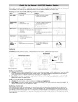
4. Packaged Contents
Before setting up, carefully unpack the contents onto a table or flat
surface and check that the following are complete:
Item: Consisting of: Fittings: Illustration:
Base
Station
• Main unit
• AD/DC 240V power
Adaptor - optional use
(included)
Thermo-
Hygro
Sensor
• Main unit
• Rain
protection
cover
• 10 metre cable -
optional connection to
the base station
(included)
• Wall mounting screws
• Plastic anchors for
screws
Wind
Sensor
• Main unit with
wind vane
• 10 metre
cable (already
attached to
the main unit)
• Mast holder
• 1 x U-bolts for mast
holder
• 2 x Washers
• 2 x Nuts
• 2 x cable ties to
secure wind and rain
cords
Rain
Sensor
• Main unit
(base and
funnel)
• 10 metre
cable (already
attached to
the main unit)
Heavy
weather
PC
software
(Beta 2.0)
CD-Rom format
(English version
only)
• 2 metre PC serial
cable for PC
connection - optional
use (included)

7
Battery
compartment
Sockets
and PC
COM port
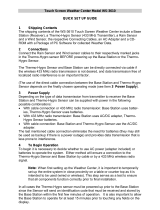
5. Setting up
It is always best to set up on a table inside before mounting your
sensors. This way you can perform a function test (section 8).
First, choose to use the 240V adaptor (included in this set) or
batteries for operation. Both these methods allow for operation using
wireless 433MHz transmission or cable connection between the base
station and the sensors and setting up for both methods is as follows:
Base Station:
Socket for
Thermo-
Hygro
Sen
sor
Socket for
Adaptor
PC COM
Port

8
Setting up using batteries:
Important: To avoid operating problems, please take note of
battery polarity if inserting any batteries.
1) Pull away the air flow cover of the thermo-hygro sensor to reveal
the three sockets (for the wind sensor, rain sensor and the base
station)
2) Connect the attached cables of wind and rain sensors to the
corresponding sockets of the thermo-hygro sensor by clicking
them into place.
3) Open the battery cover of the thermo-hygro sensor located below
the three sockets and insert 2 x AA, IEC LR6, 1.5V batteries and
close the cover.
4) Open the base station’s battery cover located at the back of the
unit and insert 3 x AA, IEC LR6, 1.5V batteries into the battery
compartment and close the battery cover.
Sensor sockets
Battery
Compartment
Battery Cover
Thermo
-
Hygro Sensor
Sensor sockets

9
Setting up using the AC adaptor:
1) Power up all the sensors as described in setting up using
batteries above.
2) Using the AC adaptor (included), plug it into the mains wall outlet
first and power up the base station by inserting the adaptor jack
into the DC 6.0V socket located on the side of the base station.
Every time the thermo-hygro sensor is powered up (for example after
a change of batteries), a random security code is transmitted and this
code must be synchronized with the base station to receive weather
data.
When the base station is powered up, a short beep will sound and all
LCD segments will light up for about 5 seconds before it enters into a
15 minute learning mode to learn the sensors security code.
E.L. backlight:
When using the power adaptor or under battery operation, the E.L.
backlight will switch on for 15 seconds when any button is pressed.
6. Operation using cable connection or wireless 433MHz
Cable Connection:
Using this method of operation will provide interference free transfer
of the weather data from the sensors to the base station. The data
sending interval from the sensors to the base station will also be more
frequent compared to using 433MHz transmission and will result in
higher power consumption. Therefore batteries will have a shorter life
span for cable connection compared to using 433MHz.
To operate using cable connection, simply use the enclosed 10 metre
cable and connect the thermo-hygro sensor to the base station. Once
the connection is detected, the base station will automatically
continue reading the data from the sensor.
The user may at any time switch from cable connection to using
433MHz (or vice versa) by simply disconnecting (or connecting) the
cable from the base station to the sensor. When the base station
detects no cable connection to the sensors, the base station will
automatically change to using 433 MHz for reception of the weather
data from the sensors.
The data receiving intervals are as follows:
- Using cable connection data is updated every 8 seconds.
- Using wireless 433 MHz data is updated from 16 to 128 second
intervals depending on wind speed and rain activity.

10
Using the AC adaptor to operate the base station will also supply
power to the sensor if the cable is connected to it. Batteries used for
433MHz transmission may be left in the sensor when using cable
connection for power back up in case of AC power failure. A loss of
power would desynchronize the base station and the sensor and no
weather data will be received. To synchronize the units so that the
weather data can be received, press and hold the PLUS (+) key for 2
seconds. However in general, batteries that will not be used for long
periods should be removed to avoid leakage.
Wireless 433MHz transmission:
Using 433MHz wireless transmission of weather data from the sensor
to the base station will provide users greater freedom as to where
units can be positioned without the need to be restricted by cable.
Note:
If no outdoor weather data is displayed or the signal to the sensors is
lost during setting up, mounting, changing of batteries to the sensor or
plugging or unplugging cables, simply press and hold the PLUS (+)
key for 2 seconds and a short beep will sound to synchronize the
base station to the sensors. Without synchronization, weather data
will not be received.

11
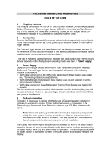
1. Low battery indicator
2. Date display
3. Time zone display
4. Date, seconds, alarm time and time
zone
5. Alarm icon
6. Weather forecast icons
7. Weather tendency indicator
8. Pressure alarm display
9. hPa/inHg air pressure unit
10. Pressure units (relative or absolute)
11. 433MHz reception icon
12. Rainfall display
13. Indoor, outdoor, humidity, dew point,
wind chill, rainfall alarm icon
14. 24h, 1h or total hour display
15. Humidity display as RH%
16. Rainfall units (inch or mm)
17. Temperature display units (ºC or ºF)
18. Outdoor temperature/humidity display
19. Indoor temperature/humidity display
20. Dew point temperature display
21. Wind chill temperature display
22. Wind alarm icon
23. Wind information for Min/Max speed
and wind speed low, high, direction
alarm
24.
Wind direction and speed (m/s, knots,
Beaufort, km/h or mph) display
25. Alarm buzzer ON/OFF icon
26. General alarm icon
7. LCD Overview
The following illustration shows the full segments of the LCD for
description purposes only and will not appear like this during
normal operation and use.
15
1
2
3
4
5
6
7
8
9
12
11
13
14
16
22
10
18
19
21
20
17
23
24
25
26

12
8. Function test
Once the weather station is powered up, perform a function test by
checking that the weather data is received. To do this, press the
DISPLAY, PRESSURE or WIND keys to toggle through the relevant
LCD sections:
1) Indoor temperature and humidity
2) Outdoor temperature and humidity
3) Outdoor wind chill
4) Dew point
5) Rainfall 24 hour
6) Rainfall 1hour
7) Rainfall Total
8) Relative and absolute pressure
9) Wind speed, wind direction and wind direction in degrees
If any readings cannot be received from the sensors, lines (- - -) will
be displayed in the respective weather sections of the LCD. In this
case, check that all cables are correctly inserted into the correct
sockets and/or check the batteries in the outdoor thermo-hygro
sensor and press and hold the PLUS (+) key for 2 seconds and a
short beep will sound to synchronize the base station to the sensors
otherwise no weather data will be received.
Some weather readings such as wind speed and direction may not
appear immediately on the LCD if the wind-fan or vane of the wind
sensor is moved. This is due to the set reading time intervals for the
wind readings. However the current wind speed or direction will be
displayed once the time reading interval is reached. For rainfall, the
interval readings may take up to 2 minutes before the data is
displayed on the LCD.
9. Mounting
Important Note
Prior to drilling mounting holes and permanently affixing any of the
units, please ensure the following points are considered:
• Cable lengths of the units meet with your distance requirements
at the point of fixing
• Signals from the sensors can be received by the base station at
points of mounting

13
Accessories: adding cable extensions
Wired Extension Cable.
When you require additional length to properly mount your sensor,
you can use a Wired Extension Cable. The Extension Cable is 10
metres in length and comes with the appropriate connecter attached.
Please visit your local electrical retailer to purchase.
Phone cable and connections have more resistance than our exten-
sion cable and is not recommended for use. Using phone ca-
ble/connection may damage your sensors.
Warning: Never cut, splice, shorten, or modify your sensor cables or
extension cables. Doing so may damage your sensors and will void
your Warranty.
Please Note: On all stations with corded sensors, the thermo-hygro
sensor powers the Wind and Rain sensors. Therefore, adding exten-
sions to a battery only unit will shorten battery life in the thermo-hygro
sensor.
When securing the cables during mounting, ensure that the base
station can receive the weather data since increasing the cables
length may also increase levels of interference and result with
reception difficulties. Interference levels will greatly depend on the
surrounding area for example setting up on or near metal piping may
considerably reduce reception.
For best results, do not add more than 100 metres of extension cable
from item to item onto the existing cable lengths as this may reduce
reception levels. Again, reception and interference levels will greatly
depend on the surrounding environment at your point of mounting.
Note:
It is important to keep all the connected extension heads away from
rain, moisture and other extreme weather conditions as exposure can
cause short circuits and damage to this item.
Wired Extension Cables

14
Base Station
With two foldable legs at the back of the unit, the base station can be
placed onto any flat surface or wall mounted at the desired location by
the hanging holes also at the back of the unit. It is important to check
that the 433MHz (if using wireless connection) can be received before
permanently mounting any of the units. Should the base station not
display the 433MHz weather data from the sensors, then relocate the
units. Once the signals are received, the system can be affixed. Also
if you have selected to use cable connection, ensure that distances
can reach all desired locations before affixing any unit permanently
Mounting the Wind Sensor onto a mast
First, check that the wind-fan and the wind-vane can rotate freely
before fixing the unit. For correct and accurate readings it is
important to mount the sensor so that the front (marked E) is pointing
in East-West direction. The wind cups must be below the mounting
bracket. The wind sensor should now be mounted using the screws
provided onto a mast to allow the wind to travel around the sensor
unhindered from all directions (ideal mast size should be from
Ø16mm – Ø33mm).
Place the Wind sensor as high as you can install it. In most cases
1.22-1.83 m above the peak of your roof (or more) is required for
accurate readings. (Avoid tall trees or other obstructions that may
block or reflect the wind).Carefully thread the cord through the mast
and be sure the cord fits in the slot designed to prevent pinching. Be
sure not to overtighten U bolts to mast, as they can crack the mast.
Cords should be secured from blowing about as this may cause
static.
Avoid: Transmitting antennas, using PVC pipe (unless electrical
grade), improper extension cords and modifications of the cords in
any way.
Please note most recording stations have sensors mounted 10.1
metres up or higher.
Vertical mast
Wind fan
Fixed with N
y
lon
strap

15
Once the wind sensor is fixed onto the mast, connect the cable to the
corresponding thermo-hygro sensor socket so that operating power
supply can be received and data can be transmitted to the base
station. Be sure to leave a small amount of cord below the thermo-
hygro sensor as a “drip loop” to prevent water from running into the
ports of the sensor.
It is NOT RECOMMENDED to mount the sensors with the nylon
straps as they may stretch in extreme weather. Straps are excellent to
secure wind and rain cords from blowing about.
1. Unlock the mounting bracket from the remote wind speed sensor
leaving the wire going through the bracket.
2. Place two nylon straps through the slots on the mounting bracket.
3. Place the remote wind speed sensor in your desired location.
4. Fasten the two nylon straps securely around the mounting
location.
5. Slide the remote wind speed sensor onto the bracket making
sure to lock it in place.
Mounting the Rain Sensor
Base portion
Funnel portion
Horizontal panel
Wind
vane
Fixed with
screw

16
For accurate results, the rain sensor should be securely mounted
onto a horizontal surface at least 1.0 metre above the ground and in
an open area away from trees or other coverings where rainfall may
be reduced causing inaccurate readings. Placing the gauge extremely
high is generally not a good idea as you may need to periodically
clear debris such as leaves, spider nests etc.
When securing into place, check that rain excess will not collect and
store at the base of the unit but can flow out between the base and
the mounting surface (test by pouring clean water).
Install the Rain gauge on a level platform that is stationary. If the
gauge isn't level it will read low, and if it isn't stationary wind may
cause it to read rain that isn't falling. Tip: Be sure not to screw the
rain sensor down too tightly as that will result in a low or inaccurate
reading. On the bottom of the sensor there are 4 holes that can be
used to screw the gauge down. First remove the cover. You have to
push in the tabs on the sides and then pull the cover off. There will
be a teeter-totter that has a metal bar for an axis. Pull the metal bar
out with pliers. The teeter-totter can then be removed giving you
access to the screw holes. You may also choose to mount with
25mm (1 inch) strips of silicone gel along the base. Be sure to leave
gaps for water to run out.
After mounting the rain sensor, connect the cable to the thermo-hygro
sensor at the corresponding socket so power supply can be received
and data can be transmitted to the base station. Be sure to leave a
small amount of cord below the thermo-hygro sensor as a “drip loop”
to prevent water from running into the ports of the sensor.
The rain sensor is now operable. For testing purposes, very slowly
pour a small amount of clean water into the rain sensor funnel. The
water will act as rainfall and will be received and displayed at the
base station after about 2 minutes delay i.e. when the reading interval
is reached (to clear this testing data on the base station, refer to the
section “MIN/MAX Mode” below).

17
Mounting the thermo-hygro Sensor
An ideal mounting place for the thermo-hygro sensor would be the
outer wall beneath the extension of a roof, as this will protect the
sensor from direct sunlight and other extreme weather conditions.
To wall mount, use the 2 screws to affix the wall bracket to the
desired wall, plug in the thermo-hygro sensor to the bracket and
secure both parts by the use of the supplied screw to prevent tipping
and ensure that the cables from the wind and rain sensors are
correctly plugged in otherwise data transmission errors could occur.
Place the Outdoor sensor in a well-shaded area that is protected from
direct rainfall and sun, as it will read high if exposed to the sun. If the
sensor gets too wet it will never read accurate humidity again, so take
care to ensure that it will not be exposed to a downpour. Light inci-
dental exposure to water typically will not harm the sensor.
You can also build a small roof or box for it if you do not have an
overhang. Please be sure it is well vented.
NOTE: For best 433 MHz reception mount the thermo-hygro
sensor on an outside wall near the location of the base station.
Air Flow
Cover
Wall Bracket
Main Unit

18
10. Resetting & factory settings
As previously mentioned, in the event of a power reset to the sensor
(for example a change of batteries), the base station has to
synchronize to the sensor again otherwise no weather data will be
received. To do this, simply press and hold the PLUS (+) key for 2
seconds and a short beep will sound to synchronize the base station
to the sensor. When the units are synchronized, the data will be
received again and the base station will return to normal operation
mode.
Do not remove batteries or unplug the AC adaptor of the base station
otherwise all 175 sets of recorded weather history data for
transferring to the PC will be lost (for full details of PC use, please see
PC user manual in the enclosed Heavy Weather CD-ROM).
Factory Reset: However if you wish to make a full reset of the base
station and return to the original factory settings, simultaneously press
and hold the PRESSURE and WIND keys for about 10 seconds. The
base station will beep once and the entire LCD will light up for 5
seconds and go back to the original factory settings. This process will
clear all previous user defined values and all weather history
recordings.
Factory default settings:
The following table shows the factory default values of the weather
station:
Matter: Default Setting:
Time 0:00
Date 01.01.2001
Time zone 0
Alarm time 0:00
Relative air pressure 1013.0 hPa
Weather-picture threshold 3 hPa
LCD contrast level 5 (1-8 levels)
Rainfall per impulse 0.518mm
Storm alarm 5 hPa
Relative air pressure
alarm
960.0 hPa
(low)
1040.0 hPa
(high)
Indoor temperature alarm 10.0°C (low) 30.0ºC (high)
Outdoor temperature
alarm
0.0ºC (low) 40.0ºC (high)
Indoor humidity alarm 35%RH (low) 65%RH (high)
Outdoor humidity alarm 45%RH (low) 70%RH (high)
Wind chill alarm 10.0ºC (low) 30.0ºC (high)

19
Dew point alarm 0.0ºC (low) 20.0ºC (high)
Rainfall 24h alarm 50.0mm
Rainfall 1h alarm 1.0mm
Wind Speed 1km/h (low) 100km/h (high)
Wind direction alarm None set
Note:
All alarm default values are deactivated at the start up and any alarm
must be activated by the user otherwise it will not sound.
11. Function Description of the Weather Station
After setting up, the following data will be displayed in different
sections on the LCD. If this is not the case please observe the notes
on “Interferences” below.
Time & Date (LCD Section 1)
Press the PLUS (+) key to change the format of date display between
date/month/year, weekday/date/month, seconds, alarm set time and
time zone.
LCD Section 1:
Time, date, seconds, time zone,
weather forecasting icons with
tendency arrows, air pressure,
and respective alarms sections
LCD Section 2
:
Indoor and outdoor temperature
and relative humidity, wind chill,
dew point, rainfall, and
respective alarms se
c
tions
LCD Section 3:
Wind direction, wind speed, and
respective alarms sections
/