Page is loading ...

INSTALLATION INSTRUCTIONS
for the
Asepsis 21 Duo Wall /Cabinet Mount
SECTION I - REQUIREMENTS
1. PHYSICAL REQUIREMENTS................................................................................... 1
2. SUGGESTED ROOM LAYOUT ................................................................................. 2
3. ELECTRICAL REQUIREMENTS .............................................................................. 2
4. WATER SUPPLY REQUIREMENTS ......................................................................... 2
5. AIR SUPPLY REQUIREMENTS ................................................................................ 2
SECTION II - INSTALLATION
1. UNPACKING THE CARTONS ................................................................................... 3
2. UTILITIES CONNECTION BOX (J BOX) INSTALLATION ......................................... 3
3. ELECTRICAL CONNECTIONS TO THE CONNECTION BOX (J BOX) .................... 3
4. INSTALLING THE MOUNT & FLEX ARM (WALL MOUNT ALTERNATIVE) ............ 4
5. INSTALLING THE MOUNT & FLEX ARM (CABINET MOUNT ALTERNATIVE) ...... 5
6. INSTALLING THE DUO UNIT ................................................................................... 6
7. TUBING CONNECTIONS ......................................................................................... 7
8. UMBILICAL TUBING CONNECTIONS
TO THE UTILITIES CONNECTION BOX (J BOX) ....................................................... 8
SECTION III - CONTROLS
1. ASEPSIS 21 HANDPIECE DELIVERY SYSTEM CONTROLS................................. 9
2. EXTERNAL CONTROLS AND FUNCTIONS .......................................................... 10
SECTION IV - PURGING AND TESTING THE SYSTEM
PURGING AND TESTING THE SYSTEM .................................................................... 11
SECTION V - FINAL CHECK LIST
FINAL CHECK LIST ...................................................................................................... 12
TPW1494 Rev. L
TM
Style F

Duo Wall/Cabinet Mount Installation Instructions - 1
INSTALLATION INSTRUCTIONS
for the
Asepsis 21
Duo Wall /Cabinet Mount
(Rear Delivery System)
TM
SECTION I -REQUIREMENTS
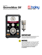
1. PHYSICAL REQUIREMENTS
Before installing, ensure that the physical requirements of the unit are met (See Figure 1 and 2). This unit is
designed to be mounted to a wall or cabinet and to function as a rear delivery system.
Figure 1
12.00" RANGE
OF TRAVEL
32.00"
FLOOR
48.00"
WAL L
AF1156
WALL
21.00"
17.50"
FLOOR
24.00"
12.00"
32" Low Position
44" High Position
15.25"
22.00"
27.52"
13.75"
FLOOR
3.62"
5/16-18 Screw
(4 Required)
FLOOR
15.50" 4.00"
Cabinet Mount Alternative
(Mount Without
Wall Frame)
See Figure 3
for wall frame
mounting dimensions
Return To Table Of Contents

2 - Duo Wall/Cabinet Mount Installation Instructions
2. SUGGESTED ROOM LAYOUT
The room layout shown is a suggestion and is
not meant to be restrictive in any way. This layout
may be altered to fit the situation or suit the
doctor's personal preferences (See Figure 2).
3. ELECTRICAL REQUIREMENTS
Before connecting the line cord to an appropriate
receptacle, make certain that the circuit is
protected by a 15-amp circuit breaker for 120-
VAC models, or a 7.5-amp breaker for 240-VAC
models. Ensure that all wiring is grounded and
all electrical codes are observed.
WARNING - Potential shock hazard
with possible personal injury. To
reduce shock hazard, observe all
electrical codes.
4. WATER SUPPLY REQUIREMENTS
A 1/2 I.D. copper supply line, reduced to 3/8"
O.D. copper tubing as near the shut-off valve as
possible is required. The water pressure should
be in the range of 30-50 psi. A suitable pressure
reducing valve is essential for trouble free
operation if the pressure exceeds the
recommended range.
5. AIR SUPPLY REQUIREMENTS
A 1/2" I.D. copper supply line reduced to 3/8"
O.D. copper tubing as near the shut-off valve as
possible is required.
The air pressure must be between 75-100 psi at
the valves. A pressure reducer should be
installed if the pressure exceeds 100 psi.
For maximum life and trouble free operation, the
air supply must be clean and dry. It is
recommended that a moisture separator and
filter be installed as near the connection as
possible and accessible for periodic cleaning.
SECTION I - REQUIREMENTS (CONT)
Figure 2
Return To Table Of Contents

Duo Wall/Cabinet Mount Installation Instructions - 3
SECTION II - INSTALLATION
1. UNPACKING THE CARTONS
The unit is shipped in two cartons containing the
following items:
LARGE BOX
Large work surface
Asepsis 21 instrument head and fixed arm
assembly
Flex arm assembly
Tub or tray assembly
SMALL BOX
Wall mounting frame and cover
Wall mount kit (bearing plate, hardware, etc.)
Installation instructions (this manual), an
operator’s manual, and warranty card
Check for signs of damage to the carton or to the
contents. Make sure all items listed above are
present. If there is any evidence of damage due to
shipping or if any of the items are missing from the
carton, notify the shipper at once. Be careful not to
discard any small parts or instruction sheets with
the packing material.
2. UTILITIES CONNECTION BOX
INSTALLATION
The installation of the utilities connection box should
be performed by a qualified technican. Refer to the
installation plan TP1191 supplied with the
connection box. This plan may be used as a
template to locate the utilities for connection.
Please consider the following before beginning:
The connection box can be installed anywhere
in the room within the range of the 8 foot
umbilical that will connect the box to the unit.
Locate the box where the incoming service
lines will not cause an obstruction.
Air and water are the only services required
unless a heated syringe or lighted handpieces
are to be used.
Waste lines, vacuum lines or auxiliary low
voltage wiring are not necessary unless
separate devices requiring these services are
to be used.
The location of the incoming services on the
installation plan are suggestions and can be
altered to suit the situation.
3. ELECTRICAL CONNECTIONS TO THE
CONNECTION BOX (J BOX)
Domestic - Make the electrical connections to the
J box as shown in Instruction TPW1487.
International - Make the electrical connections to
the J box as shown in Instruction TPW1511. These
J boxes have accessible fuses located on the front
of the box.
DANGER: Turn off all electrical power
at the power source before making
primary electrical connections.
RATING FOR 120 VOL T UNIT
KNIGHT by MIDMARK, Versailles, Ohio USA
120 VOLTS 50/60 Hertz Air: 80/100 PSI
Water: 30/50 PSI
15 amps Max Total Connected Load
RATING FOR 240 VOL T UNIT
KNIGHT by MIDMARK, Versailles, Ohio USA
240 VOLTS 50/60 Hertz Air: 80/100 PSI
Water: 30/50 PSI
7.5 amps Max Total Connected Load
Return To Table Of Contents

4 - Duo Wall/Cabinet Mount Installation Instructions
SECTION II - INSTALLATION (CONT)
4. INSTALLING THE MOUNT AND FLEX
ARM (WALL MOUNT ALTERNATIVE)
The unit can be attached to any wall sound enough
to support the unit in operation. Please use the
following instructions:
1. The unit is supplied with a mounting frame that
has been predrilled with 8 mounting holes on
16" centers. Use the frame as a template to
locate these holes on the wall (See Figure 3).
2. Using the eight lag screws and washers
provided, attach the frame to the wood studs
of a wood frame constructed wall (See
Figure 4).
3. Attach the frame cover to the frame using the
four #10 panel screws provided.
4. Mount the flex arm assembly and the bearing
plate to the mounting frame using four 1/4"-20
hex bolts and washers. Do not tighten all the
way.
5. Check the level at the flex arm bearing housing
(See Figure 5). Using the four adjustment set
screws in the flex arm mount, make sure the
flex arm is plumb in all positions. Tighten the
four 1/4"-20 Hex Bolts that were left loose in
step 4.
Figure 3
Figure 5
Figure 4
FLEX
ARM ASSY
#10 PANEL
SCREW
A
DJUSTMENT
SET SCREWS
BEARING
PLATE
FRAME
COVER
FRAME
WALL
2 x 4 STUD
1/4-20 HEX BOLT
(For wall mount)
FLAT WASHER
5/16 LAG
SCREW
AF1159
WASHER
LOCKWASHER
AF1162
WALL
FRAME
MARK 8 MOUNTING
HOLE LOCATIONS
ON WALL
2 x 4 STUD
FLEX ARM
BEARING HOUSING
A
F1166
SPIRIT LEVEL
Return To Table Of Contents

Duo Wall/Cabinet Mount Installation Instructions - 5
SECTION II - INSTALLATION (CONT)
Figure 6
5. INSTALLING THE MOUNT AND FLEX
ARM (CABINET MOUNT
ALTERNATIVE)
The unit can be attached to any cabinet sound
enough to support the unit in operation. Please use
the following instructions:
1. Using the bearing plate as a template, located
and drill the mounting holes (See Figure 6).
2. Install the bearing plate on the cabinet by
inserting two 8-32 painted screws through the
bearing plate and into the 1/4" holes in the
cabinet. Position the backing plate on the back
side of the cabinet and tighten the screws (See
Figure 7).
3. Mount the flex arm assembly onto the bearing
plate using four 1/4"-20 hex bolts and washers.
Do not tighten all the way.
4. Check the level at the flex arm bearing housing
(See Figure 5). Using the four adjustment set
screws in the flex arm mount, make sure the
flex arm is plumb in all positions. Tighten the
four 1/4"-20 Hex Bolts that were left loose in
step 3.
A
F
1
1
6
3
CABINET
DRILL THRU
1/4" 2 PLACES
DRILL THRU
3/8" 4 PLACES
USE BEARING PLATE TO
LOCATED HOLES FOR DRILLING
5/16-18 SCREW
8-32 PAINTED
SCREW
WASHER
AF1160
CABINET
BACKING
PLATE
(threaded
holes)
A
DJUSTMENT
SET SCREWS
FLEX
ARM ASSY
BEARING PLATE
Figure 7
Return To Table Of Contents

6 - Duo Wall/Cabinet Mount Installation Instructions
6. INSTALLING THE DUO UNIT
After the mount and flex arm assembly is installed
and level, the duo unit fixed arm assembly is
mounted to the flex arm. Please use the following
instructions:
1. Remove the bottom cover by removing the four
screw covers, screws and screw bases (See
Figure 8).
2. Thread the full length of the umbilical down
through the flex arm bearing and insert the fixed
arm hub into the flex arm bearing (See Figure 9).
Make certain the plastic washer is in
the position shown in Figure 7 before
seating the fixed arm hub into the
bearing.
3. Tighten the lower 1/4"-20 set screw (stainless
steel) to hold the outer umbilical hose in the
bearing.
4. Tighten the upper 1/4"-20 set screw ( brass
tipped) until the desired fixed arm rotation
friction is obtained.
5. Connect the 1/8" green air brake control tube
(located at the mid point of the umbilical) to the
1/8" green air brake cylinder tube (located
through the access hole on the bottom of the
flex arm .
6. Replace the bottom cover. Take care not to
pinch the green air brake control tube.
6. Route the umbilical to the utilities connection
box and make the connections (See Figure 10
and 11).
SECTION II - INSTALLATION (CONT)
FLEX ARM
SCREW COVER
SCREW
BOTTOM COVER
SCREW BASE
AF1165
Figure 9
Figure 8
FLOOR
WALL
DUO UNIT
FIXED ARM ASSY
FLEX ARM BEARING
BRASS TIPPED
SET SCREW
STAINLESS STEEL
SET SCREW
PLASTIC
WASHER
FIXED
A
RM HUB
BOTTOM COVER
BUTTON HEAD SCREWS
CONNECTION
FOR AIR BRAKE
FLEX ARM
ASSY
1/2"-20
SET SCREW
PRE-SET
UMBILICAL
AF1164
Return To Table Of Contents

Duo Wall/Cabinet Mount Installation Instructions - 7
Figure 10
7. TUBING CONNECTIONS
When connecting the umbilical tubings to the unit
or other tubing, use the plastic retainers to secure
the connection (Refer to Figure 10).
1/8" Tubing Connection
1. Slip the retainer (large end first) onto the tubing.
2. Push tubing onto the barb fitting and slide the
retainer forward over the tubing on the barb
fitting.
3. Break the large collar loose and slide it toward
the fitting and over the small collar.
1/4" Tubing Connection
1. Slip the retainer onto the tubing with the large
opening toward the end of the tubing.
2. Push the tubing onto the barb fitting.
3. Slide the retainer over the tubing on the barb
fitting.
SECTION II - INSTALLATION (CONT)
Return To Table Of Contents

8 - Duo Wall/Cabinet Mount Installation Instructions
8. UMBILICAL TUBING CONNECTIONS TO THE UTILITIES CONNECTION BOX (J BOX)
SECTION II - INSTALLATION (CONT)
Figure 11 shows the connections to be made inside
the J box. Refer to installation plan TP1191
supplied. This plan may be used as a template to
locate the utilities for connection. The installation
should be performed by a qualified technician.
Figure 11
WATER
AIR
ELECTRICAL
BOX
2" x 4"
BOX FOR
POWER
SUPPLY
(not supplied)
UMBILICAL
VACUUM
HOSE
1/4" BLUE
WATER TUBE
FROM
UMBILICAL
3/8" BLACK
AIR TUBE
FROM
UMBILICAL
3/8"
TUBE
SUPPLIED
1/8" RED
AIR TUBE
FROM
UMBILICAL
WATER
SHUT OFF
VALVE
IN
OUT
Return To Table Of Contents

Duo Wall/Cabinet Mount Installation Instructions - 9
1. ASEPSIS 21 HANDPIECE DELIVERY SYSTEM CONTROLS LOCATED UNDER COVER
A complete set of handpiece and syringe adjustments are located directly under the magnetically held cover
for protection against contamination. Lift up either back corner of cover for easy removal. All controls are
labeled with symbols identifying their function. A description follows and their locations are identified below.
I 2 3 HANDPIECE COOLANT WATER
VOLUME
Adjusts the amount of coolant water to each
respective handpiece.
4 5 6 DRIVE AIR PRESSURE SETTING
Individual adjustments are provided - one for
each respective handpiece. Use to set
maximum handpiece pressure indicated on
gage. Refer to handpiece manufacturer’s
specifications for proper setting.
7 SYRINGE AIR VOLUME ADJUSTMENT
Controls the volume of air to the syringe and
effects air water spray pattern.
8 SYRINGE WATER VOLUME ADJUSTMENT
Controls the volume of water to the syringe and
effects water spray pattern.
SECTION III - CONTROLS
Figure 12
9 COOLANT AIR VOLUME ADJUSTMENT
This adjustment controls the volume of coolant
delivered to each handpiece. It effects the spray
pattern of air and water at the handpiece. If the
handpiece has a coolant air connection in the
handpiece itself, this adjustment will have no
effect and can be completely shut off.
I 0 HANDPIECE PRESSURE GAGE
Indicates individual handpiece pressure when
handpiece is operating.
11 12 13 MAGNETIC LATCHES
These hold the cover in place.
14 HANDPIECE COOLANT WATER FLUSH
BUTTON
controls the coolant water flush valve located
on the underside of the delivery head.
Return To Table Of Contents

10 - Duo Wall/Cabinet Mount Installation Instructions
2. EXTERNAL CONTROLS AND FUNCTIONS:
MASTER ON /OFF VALVE
Located on the bottom of the instrument head
directly behind the handpiece holder bar
support, this two position toggle control turns
the main air and water on or off the utilities box.
Up position is on.
AUTOMATIC HANDPIECE ACTIVATION
The automatic kink valves are designed to
permit activation of the selected handpiece
when it is removed from its holder. Drive air
will be delivered to the withdrawn handpiece
when the foot control is depressed.
WET/DRY FOOT CONTROL
The disc-type foot control operates the selected
handpiece at varying speeds depending upon
the foot pressure applied to the disc.
Positioning the coolant water selector toggle
allows coolant water for wet cutting to be
selected by the motion of the foot. Applying
foot pressure to the disc will operate the
selected handpiece and, if turned on, water
spray.
WATER ON/OFF VALVE
Located on the foot control, this switch provides
water for coolant spray to the handpiece when
the switch is moved forward to the “On” position
(toward blue dot) and the foot control is
depressed (wet cutting). When the valve is in
the “Off’ position, water will not be delivered to
any handpiece.
WATER OUTLET AND FLOW CONTROL
Located on the front panel of the unit, the water
outlet provides water for hydrocolloid tubing or
other accessories. The water is controlled by
a flow control knob located next to the water
outlet. Turning the knob clockwise will
decreases water flow and counterclockwise
increases the flow.
ASSISTANT'S INSTRUMENTATION
A saliva ejector, HVE and syringe are standard
instrumentation on the unit. They are positioned
on a movable holder that slides into the console
or on the chair headrest.
SECTION III - CONTROLS (CONT)
Return To Table Of Contents

Duo Wall/Cabinet Mount Installation Instructions - 11
When the installation is complete you should purge the system to clear the tubing of
any foreign material and to purge the air out of the water tubing. This also serves to
test the equipment for proper function.
1. Before attaching the handpieces, turn on the
air, water and vacuum to the utilities
connection box.
2. Open the shut-off valves in the utilities
connection box.
3. Turn on the master valve lever on the Asepsis
21 head.
4. Lift the cover off the Asepsis 21 head and
turn the coolant water and coolant air volume
controls adjustment knobs completely open.
5. Remove a handpiece hose from its holder.
6. Depress the foot control to operate the coolant
water and drive air for 30 seconds.
7. Depress the coolant water flush button on the
underside of the Asepsis 21 head to allow
the water to flow for 30 seconds.
8. Repeat this procedure with each handpiece
hose.
9. Operate the air and water for both doctor and
assistant's syringes for 30 seconds.
10. Install the handpieces.
11. Set the coolant water and coolant air volume
controls to the desired position.
SECTION IV - PURGING AND TESTING THE SYSTEM
Return To Table Of Contents

12 - Duo Wall/Cabinet Mount Installation Instructions
SECTION V - FINAL CHECK LIST
When all the assembly and installation procedures are completed, the unit should be
checked out in accordance with the following check list to ensure that assembly is
complete and that all controls function properly.
Check complete system for any air or water leaks.
Check to make sure there is proper air and water flow to the handpieces.
Check the drive air pressure for the handpiece being used to make sure it is set correctly.
Check the syringes for proper function and water flow.
Be sure the person who will operate the unit receives the Operator's Manual and any other appropriate
information or instructions.
If any optional equipment has been installed, make sure it is properly installed and functioning as intended.
Return To Table Of Contents


Midmark Corporation P O Box 286 60 Vista Drive
Versailles Ohio 45380-0286 www.midmark.com
Phone: 937-526-3662 Fax: 937-526-5542
Return To Table Of Contents
/