American Standard 238AA115.020 Installation guide

Category
Sanitary ware
Type
Installation guide
REMOVE OLD TOILET
a. Close toilet supply valve and flush tank completely. Towel or sponge remaining water from tank and bowl.
b. Disconnect and remove supply line. NOTE: If replacing valve, first shut off main water supply!
c. Remove old mounting hardware, remove toilet and plug floor waste opening to prevent escaping sewer gases.
d. Remove closet bolts from flange and clean away old wax, putty, etc. from base area.
NOTE: Mounting surface must be clean and level before new toilet is installed!
SAVE FOR FUTURE USE
3
2
1
CLOSET
FLANGE
CLOSET
BOLTS
7301416-100 Rev. L 1/16
A
FINISHED WALL
FINISHED FLOOR
SUPPLY
AS
REQ'D.
CAUTION: PRODUCT IS FRAGILE. TO AVOID BREAKAGE AND POSSIBLE INJURY HANDLE WITH CARE!
Product names listed herein are trademarks of AS America Inc.
© AS America Inc. 2016
NOTE: Pictures may not exactly define contour of china and components.
ROUGHING-IN DIMENSIONS:
NOTE: Distance from wall to closet flange centerline must be as listed below:
A = 12" (305mm)
A
WAX RING
SEALANT
5
4
INSTALL WAX SEAL
Invert toilet on floor (cushion to prevent damage),
and install wax ring evenly around waste flange
(horn), with tapered end of ring facing toilet. Apply
a thin bead of sealant around toilet base.
POSITION TOILET ON FLANGE
a. Unplug floor waste opening and install toilet on closet flange so bolts project
through mounting holes.
b. Loosely install retainer washers and nuts. Side of washers marked "THIS
SIDE UP" must face up!
CLOSET
BOLT
NUT
TAPERED
WASHER
FLANGE
Thank you for selecting American Standard – the benchmark of fine quality for over 100 years. To ensure
this product is installed properly, please read these instructions carefully before you begin. (Certain
installations may require professional help.) Also be sure your installation conforms to local codes.
!
INSTALLATION INSTRUCTIONS
Siphonic Ultra-High Efficiency Two-Piece Toilets
H2Optimum
Single Flush Models 288AA / 288CA / 288DA
H2Option
®
Dual Flush Models 2886 / 2887 / 2889
Certified by
IAPMO R&T
INSTALL CLOSET BOLTS
Install closet bolts in flange channel
and slide into place parallel to wall.
RECOMMENDED TOOLS AND MATERIALS
Putty Knife Regular Screwdriver Adjustable Wrench Sealant Tape Measure
Hacksaw Wax Ring/Gasket Flexible Supply Tube Closet Bolts Carpenters Level
7301416-100 Rev. L 1/16
6
8
7
INSTALL TOILET
a. Position toilet squarely to wall and, with a rocking motion, press bowl
down fully on wax ring and flange. Alternately tighten nuts until toilet
is firmly seated on floor.
CAUTION:
DO NOT OVERTIGHTEN NUTS
OR BASE MAY BE DAMAGED!
b. Install caps on washers. (If necessary, cut bolt height to size before
installing caps.)
c. Smooth off the bead of sealant around base. Remove excess sealant.
INSTALL TANK
a. Insert rubber grommets through holes in the tank then
insert bolts through holes in the grommets.
b. Install large rubber gasket over threaded outlet on bottom
of tank and lower tank onto bowl so that tapered end of
gasket fits evenly into bowl water inlet opening.
c. With tank parallel to wall, alternately tighten nuts until tank
is snugged down evenly against bowl surface.
INSTALL TOILET SEAT Install toilet seat in accordance with manufacturer's directions.
CLOSET FLANGE
CLOSET BOLT
NUT
WASHER
BOLT CAP
!
- 2 -
CAUTION:
DO NOT OVERTIGHTEN NUTS MORE
THAN REQUIRED FOR A SNUG FIT!
9a 9b
Before continuing, determine the type of water supply connection you have from the chart below
and use the appropriate assembly parts required to properly reconnect the water supply.
CAUTION: DO NOT USE
CONE WASHER WITH
PLASTIC SUPPLY LINE.
These parts must be used as
illustrated to ensure water-tight
connection. Use of existing
coupling nut may result in water
leakage. Water supply tube or
pipe must extend at least 1/2"
inside threaded shank of valve
(does not apply to flanged tubing).
Use existing coupling
nut and washer.
Use existing spiral cone
washer. Fluidmaster cone
washer may not seal
completely on spiral type
supply line.
Captive cone washers
already included. No
additional washers needed.
CAUTION: Overtightening of LOCK
NUT or COUPLING NUT could result
in breakage and potential flooding.
METAL / COPPER
FLARED TUBING
METAL FLANGED
TUBING
METAL SPIRAL
TUBING
VINYL / BRAIDED
CONNECTOR
LOCK NUT
LOCK NUT
LOCK NUT
LOCK NUT
COUPLING
NUT
COUPLING
NUT
EXISTING
COUPLING
NUT
COUPLING
NUT
WATER
SHUT-OFF
WATER
SHUT-OFF
WATER
SHUT-OFF
WATER
SHUT-OFF
CONE
WASHER
EXISTING
CONE
WASHER
EXISTING
WASHER
!
!
WARNING: Do not use plumbers putty, pipe dope, or any other sealant on the water supply
connection to this tank. If the connection leaks after hand tightening, replace the supply line. If
the connection continues to leak with the new supply line, replace the fill valve.
Warranty is void if any type of sealant is used on the water supply connection.
With correct washers in place (see
Step 9a), tighten COUPLING NUT
1/4 turn beyond hand tight.
DO NOT OVERTIGHTEN.
RUBBER
GASKET
TANK MTG.
BOLTS
WASHER/NUT
RUBBER
GROMMET
7301416-100 Rev. L 1/16
- 3 -
10
FLUSH BUTTONS ON TANK
The Light Flush Button (with 3 dots) should line up over the blue actuator on the flush tower in the tank.
The Heavy Flush Button (with 9 dots) should line up over the white actuator on the flush tower in the tank.
Light Flush Button (with 3 dots) for liquid waste.
Heavy Flush Button (with 9 dots) for solid waste.
TIPS:
If the bowl still does not flush properly after following the steps outlined in the troubleshooting guide, remove the tank lid and push one of the flush
buttons on top of the flush valve in the tank. If the flush appears to be normal, you will need to adjust the length of the threaded rods for the push
buttons mounted on the tank lid with the settings as follows:
1. Turn the lid upside down.
2. Loosen the black plastic lock nut.
3. Adjust the white threaded rod one turn counterclockwise.
4. Re-tighten the black plastic lock nut.
5. Put lid back on tank and test the flush. If it is still not flushing properly, repeat Tips Steps 1 through 4 (above) until the problem is resolved.
6. If one counterclockwise turn is too much and causes the flush valve to stay open, adjust 1/2 turn clockwise and tighten lock nut.
A
WHITE
THREADED ROD
INSTALL & ADJUST ROD
LENGTH TO 2-7/8" (75mm)
BLACK PLASTIC
LOCK NUT
BLACK PLASTIC
LOCK NUT
WHITE
THREADED ROD
Install the Button Rods (see A below) by threading into
lower button until 2-7/8" (75mm) rod length is achieved.
ADJUSTMENTS
a. Adjust water level. Water level should be adjusted
to level indicated on tank by adjusting as follows:
1. Major water level adjustment - see Page 4
2. Minor water level adjustment - see Page 4
b. Flush Valve Setting Adjustments
*
:
c. Refill Control set at 2
NOTE: All other settings will result in either more
or less water and are not recommended.
To remove Flush Valve, apply slight
downward pressure and twist it until the
flush valve disengages from the bayonet.
To reinstall Flush Valve, reverse the
above procedure.
FLUSH VALVE
SETTINGS
Heavy Flush Float
Heavy Flush Door
Light Flush Float
Rell Float Cup
Rell Door
8
5
12
8
2
WITHOUT
LINER
5-1/2
5
9
7
2
WITH
LINER
4
2
9
8½
0
FULL
MIN
2#-01
POM
MAX
7
5
3
1
1
1
FULL
MIN
2#-01
POM
MAX
7
5
3
1
7
5
3
1
1
1
PUSH BUTTON
SILICON
SEAL
WATER LINE
HALF
MIN
2#-01
POM
MAX
1
1
6
5
HEAVY FLUSH
FLOAT
ADJUSTMENT
*
HEAVY FLUSH
DOOR
ADJUSTMENT
*
LIGHT FLUSH
FLOAT
ADJUSTMENT
*
REFILL DOOR
*
REFILL
FLOAT
CUP
*
2
FULL
MIN
MAX
7
5
3
1
1
1
DUAL FLUSH MODELS ONLY
FOR SINGLE FLUSH MODELS GO TO STEP 11
Continued on
next page
See table (Step 10b) for
Flush Valve Setting Adjustments
*
7301416-100 Rev. L 1/16
- 4 -
11
MAJOR WATER ADJUSTMENT
MINOR WATER ADJUSTMENT
Remove the clip as per the drawing.
Install the clip as per the drawing.
BODY
CLIP
SCREW
SCREW
INLET PIPE
Unscrew the fill valve body
counterclockwise, push the
body up or down to the desired
height and refasten valve body
by turning clockwise.
1 2
BODY
CLIP
INLET PIPE
3
1 2 3
Slide tab in the “Open” direction
as shown in the drawing.
To reduce water level:
lower the float to the
desired height and rotate
the thumb screw
counterclockwise. This
will move the float down.
(As per drawing)
To increase water
level: Rotate thumb
screw clockwise, lift the
float and the water
level will correspond.
Set the float to the
desirable position.
(As per drawing)
Slide the tab to the “CLOSE”
position as per the drawing.
CLIP
CLIP
Adjust water level to level indicated on
tank by turning water level adjustment
knob to move float cup up or down.
WATER LEVEL
ADJUSTMENT KNOB
TRIP LEVER ROD
FLUSH
VALVE
FLAPPER
WATER SUPPLY LINE
TANK TO BOWL GASKET
APPROXIMATE
WATER LEVEL
FLUSH
VALVE
CHAIN
FILL VALVE
OR WATER
CONTROL
FLOAT CUP
FLOAT
REFILL TUBE
OVERFLOW
TUBE
FLAPPER
SEAL
WATER LEVEL ADJUSTMENT (DUAL FLUSH TANK ONLY)
SINGLE FLUSH MODELS ONLY
CARE AND CLEANING
When cleaning your toilet, wash it with mild, soapy water, rinse thoroughly with clear water and dry with a soft cloth. Avoid
detergents, disinfectants, or cleaning products in aerosol cans. NEVER use abrasive scouring powders or abrasive pads on
your toilet seat. Some bathroom chemicals and cosmetics may damage the seat's finish.
WARNING: Do not use in-tank cleaners. Products containing chlorine (calcium hypochlorite) can seriously damage fittings in
the tank. This damage can cause leakage and property damage.
American Standard shall not be responsible or liable for any tank fitting damage caused by the use of cleaners
containing chlorine (calcium hypochlorite).
!
7301416-100 Rev. L 1/16
- 5 -
In the United States:
American Standard Brands
P.O. Box 6820
Piscataway, New Jersey 08855
Attention: Director of Customer Care
For residents of the United States, warranty
information may also be obtained by calling
the following toll free number: (800) 442-1902
www.americanstandard.com
In Canada:
AS Canada, ULC
5900 Avebury Rd.
Mississauga, Ontario
Canada L5R 3M3
Toll Free: (800) 387-0369
www.americanstandard.ca
In Mexico:
American Standard B&K Mexico
S. de R.L. de C.V.
Via Morelos #330
Col. Santa Clara
Ecatepec 55540 Edo. Mexico
Toll Free: 01-800-839-1200
www.americanstandard.com.mx
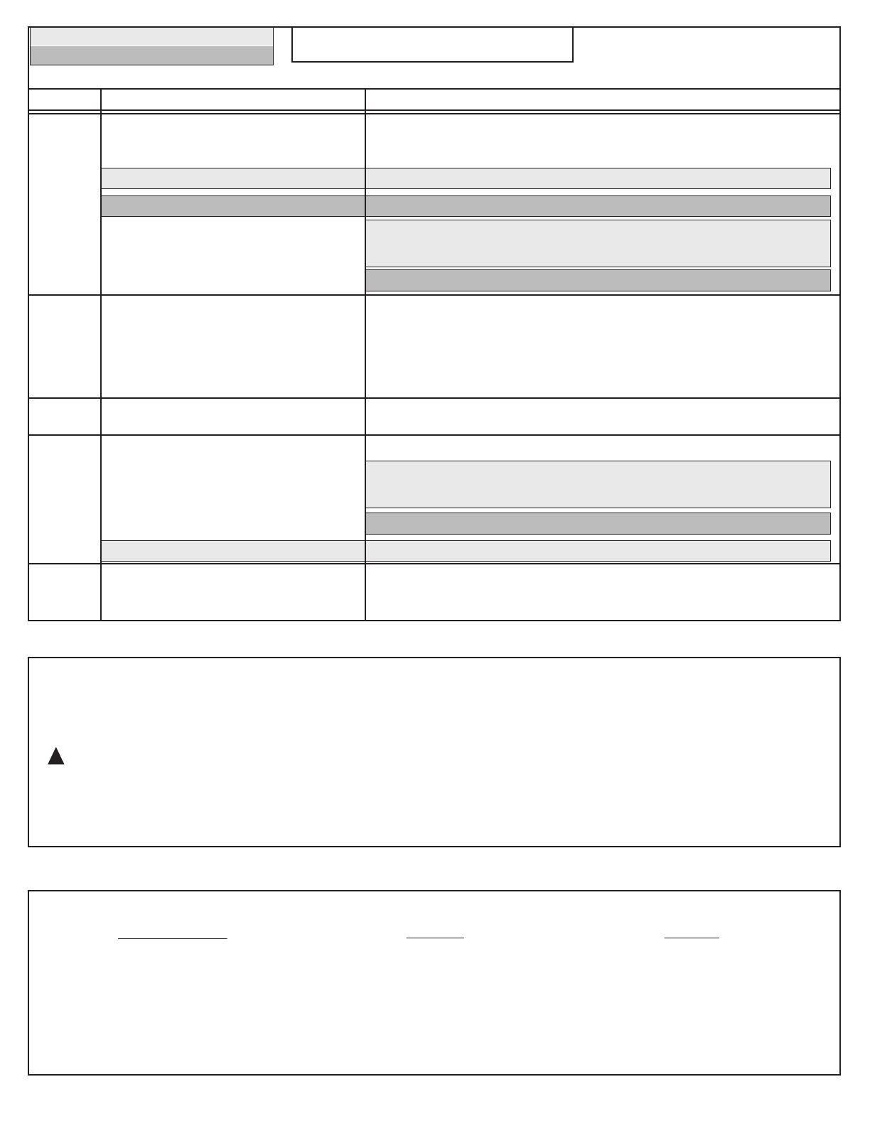
Does not
flush
Poor or
sluggish
flush
Toilet leaks
Toilet does
not shut off
Toilet bowl
rocks after
installation
a. Water supply valve closed.
b. Supply line blocked.
*c. Flush valve chain too loose or disconnected.
**c. Push button requires adjustment.
d. Sand or debris lodged in water control.
a. Bowl water level too low.
b. Supply valve partly closed.
c. Partially clogged trapway and/or drain pipe
and/or vent.
d. Supply pressure too low.
a. Poor supply line connection.
b. Poor bowl to tank/floor connection.
a. Flapper seal leaking or deformed.
b. Sand or debris lodged in water control.
*c. Flush valve chain too tight, holding flapper open.
a. Wax ring not fully compressed.
b. Floor not level.
a. Open valve and allow water to fill tank.
b. Shut off water supply, disconnect supply line and inspect all gaskets
and washers. Reassemble.
*c. Readjust chain length as required. See Step 11.
**c. Install Push Button Rods for 2-7/8" (75mm) extended length. See Step 10.
*d. Shut off water supply. Remove cap and clean as per Fluidmaster
maintenance instructions at:
www.americanstandard-us.com/enews/fluidmasterguide.pdf
**d. Shut off water supply. Remove supply line, remove & clean inlet port filter.
a. Check that refill tube is connected to water control and
inserted into overflow tube without being kinked or damaged.
b. Open supply valve fully. Be sure that proper supply tube size is used.
c. Remove obstruction. Consult a plumber if necessary.
d. Normal supply pressure must be at least 20 psi.
a. Review Steps 9a and 9b of installation procedure.
b. Review Steps 1 through 7 of installation procedure.
a. Clean debris from seal surface. Replace flapper seal as needed.
*b. Shut off water supply. Remove cap and clean as per Fluidmaster
maintenance instructions at:
www.americanstandard-us.com/enews/fluidmasterguide.pdf
**b. Shut off water supply. Remove supply line, remove & clean filter inlet port.
*c. Readjust chain length as needed. See Step 11.
a. Retighten bowl-to-floor knobs.
b. Use toilet shims and /or place a bead of caulk around the base of the toilet.
Problem Possible Cause Corrective Action
* for SINGLE FLUSH Models ONLY
** for DUAL FLUSH Models ONLY
TROUBLESHOOTING GUIDE
  • Page 1 1
  • Page 2 2
  • Page 3 3
  • Page 4 4
  • Page 5 5

American Standard 238AA115.020 Installation guide

Category
Sanitary ware
Type
Installation guide

Ask a question and I''ll find the answer in the document

Finding information in a document is now easier with AI