Page is loading ...

110 SERIES SUBWOOFERS
110TB (Tile Bridge)
110SR (Sheet Rock)
O W N E R ’ S M A N U A L
110 Series Subwoofer

CONTENTS
TABLE OF CONTENTS
WARRANTY / DAMAGE CLAIM
110 SERIES SUBWOOFERS &
INPUT MODULES
Cabinet Options
INPUT MODULE OPTIONS
Passive
LO Pass Filter
Passive 70 Volt
INPUT MODULE OPTIONS
Passive 70 Volt with LO Pass Filter
Active
O W N E R ’ S M A N U A L
1
2
5
ACTIVE 110 INPUT MODULE CONTROLS
MECHANICAL INSTALLATION - 110TB
MECHANICAL INSTALLATION - 110TB
MECHANICAL INSTALLATION - 110TB
MECHANICAL INSTALLATION - 110SR
MECHANICAL INSTALLATION - 110SR
MECHANICAL INSTALLATION - 110SR
DIMENSIONS
110TB
110SR
TECHNICAL SPECIFICATIONS
7
6
8
9
3
4
10
11
12
14
13
110 SERIES SUBWOOFERS
Tannoy United Kingdom T: +44 (0) 1236 420199 E: enquiries@tannoy.com
Tannoy Deutschland T: 00 49 (0180) 1111 881 E: info@tannoy.com
Tannoy France T: 00 33 (0) 1 7036 7473 E: ventes@tannoy.com

WARRANTY / DAMAGE CLAIMS
Congratulations on the purchase of your Tannoy 110 Series Subwoofer.
No regular maintenance of the subwoofer is necessary.
All Tannoy professional loudspeaker products are covered by a 5 year warranty for loudspeaker components and one
year for electronic component from the date of purchase subject to the absence of misuse, overload or accidental
damage.
Claims will not be considered if the serial number had been altered or removed.
Work under warranty should only be carried out by a Tannoy Professional Dealer or Service Agent. This warranty in no
way affects your statutory rights.
For further information please contact our service dealer or distributor in your area. If you can not locate a distributor,
please contact Customer Services at Tannoy North America. (contact details provided below).
DO NOT SHIP ANY PRODUCT TO TANNOY WITHOUT PRIOR AUTHORIZATION
Our policy commits us to incorporating improvements to our products through continuous research and development.
Please confirm specifications for critical applications with you supplier.
TC Group Americas Inc.
335 Gage Ave. Unit 1
Kitchener, ON
Canada
N2M 5E1
Tel: (519) 745-1158 Fax: (519) 745-2364 TFF: (800) 525-7081
Email: [email protected]
www.tannoy.com
For further information on our warranty policies, please refer to our website. Our customer service department is available
normal office hours (EST) for questions regarding service, purchase, installation or any other technical matters.
Installation of Tannoy products should be performed by an experienced contractor familiar with local codes. Failure to
properly install and secure heavy Tannoy equipment may cause a device to fall. Tannoy can not be responsible for
damage or injury due to improperly installed equipment.
UNPACKING - DAMAGE CLAIMS
Each Tannoy product is inspected for damage and inventoried to ensure all accessories and packing materials are
included before sealing and shipping. Please keep all packaging for the duration of the warranty period.
When unpacking equipment, take note of any damages to the cardboard container and carefully inspect you Tannoy
equipment for any impact in that area. Should you have any damage, immediately notify your carrier and our Tannoy
customer service department. A return claim may be issued. You may be required to repack the equipment for pick up by
a local carrier.
Some Tannoy products will include additional parts, accessories, cables etc... and you are advised to inventory these
against the following packing lists for your particular product. If you note any shortage, please contact your local dealer.

110 SERIES SUBWOOFERS AND INPUT MODULES
This manual is intended for the owner, operator or installer of Tannoy 110 Series Subwoofers. It is a guide for installing,
setting up and operating the 110 Series in accordance with established codes and practices available at the time of
publication. It does not and can not detail all possible mounting or wire configurations. The end user is advised to retain
the advice and services of a qualified contractor who is familiar with local codes and trained in the installation of Tannoy
professional audio systems.
The 110 family of subwoofers has been engineered to deliver low frequency extension and impact from a concealed
ceiling mounted position.
The 110 series subwoofers feature a 10” long excursion driver capable of low end response down to 31 Hz and power
handling in excess of 100 Watts. Its design is fully complementary to any Tannoy full range wall or ceiling mount
loudspeaker.
Two different subwoofer cabinet designs and five different input “modules” offer a wide range of combinations that can
meet almost any installation challenge, and fit into any indoor environment.
Today’s sound reinforcement systems - whether in commercial or institutional environments - must handle program
material that demands high impact, high fidelity audio reproduction. At the same time, they must be nearly invisible. The
Tannoy 110 Series of subwoofers meet all of these criteria without compromise.
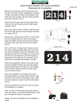
110TB (TILE BRIDGE) CABINET
Simple yet sophisticated, the 110TB is the first product of its kind: a true ceiling
mounted subwoofer. Engineered to deliver low frequency extension (-3dB @ 31 Hz)
and impact from a concealed ceiling mounted position, the 110TB integrates almost
invisibly into any indoor environment by using a standard air handling vent cover as a
speaker grille. The easy to install 110TB drops seamlessly into a 2’ x 2’ ceiling tile
without any special construction requirements. Each corner of the cabinet is fitted
with a seismic tether point. This system can also be flown in free space via 3/8”
threaded rod, chain or aircraft cable. Fire rating is NFPA class A. Whether your
application calls for low level warmth or high SPL slam, the 110TB provides the
required punch.
CABINET OPTIONS
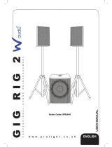
110SR (SHEET ROCK) CABINET
The second in the Tannoy family of true ceiling mounted subwoofers, the 110SR is
engineered to deliver low frequency extension (-3dB @ 31 Hz) and impact from a
concealed position. It is specifically designed for flush mount in sheet rock ceilings,
walls, overhangs or any position offering adequate clearance and suitable structural
support. The 110SR features seismic tether points, and safe and secure installation
with a sturdy pre-installation ring. The pre-installation ring is available separately for
new construction where the sheet rock installers are in ahead of the contractor. A
unique benefit of the 110SR is that it remains serviceable, and fully removable, from
the ground after installation by simply removing the low profile grille. Fire rating is
NFPA class A.

INPUT MODULE OPTIONS
PASSIVE (STANDARD)
The basic connection panel supplied with any of the 110 Series Subwoofers is a 8 Ohm speaker level input via barrier
strip. It is highly recommended that the audio signal be lo pass filtered via an outboard active crossover. This input module
is ideal for systems requiring several subs that share a common outboard crossover and amplifier.
PASSIVE 110 INPUT MODULE
SPKR LEVEL
INPUT
MADE IN CANADA
LO PASS FILTER
Speaker level inputs and outputs via barrier strip are passively filtered 100 Hz 12dB/octave LO pass for the subwoofer,
making this the ideal system for value and simplicity. The total impedance load of the satellite speaker(s) and subwoofer
should not be less than the minimum specified for your amplifier. Long wire runs to and from this module need to be an
appropriate gauge of speaker grade wire to retain proper damping and signal transfer characteristics.
LO-PASS
100Hz
PASSIVE 110 INPUT MODULE
SPKR LEVEL
INPUT
MADE IN CANADA
OUTPUT
PASSIVE 70 VOLT (Passive 70 Volt available for either option of passive units)
A 70 Volt distribution amplifier is capable of supplying power to a number of remote speakers without concern of long
cable runs or varied impedance loads (limited to the amplifier power and line load).
The passive 70 Volt module takes
advantage of this type of installation with a 60 Watt transformer as the standard. A 150W 70V transformer version is
available upon request for both 70V passive options.
PASSIVE 110 INPUT MODULE
SPKR LEVEL
INPUT
MADE IN CANADA
OUTPUT
OUTPUT
LO PASS FILTER
NO LO PASS FILTER
110
SUBWOOFER
70V 60W

INPUT MODULE OPTIONS
PASSIVE 70 VOLT WITH LO PASS FILTER
PASSIVE 110 INPUT MODULE
SPKR LEVEL
INPUT
MADE IN CANADA
OUTPUT
LO PASS FILTER
LO-PASS 100Hz
ACTIVE (ACTIVE SUBWOOFER WITH 2-CHANNEL FEED-THROUGH)
A dedicated power amplifier that really brings your 110 Series Subwoofer to life. Balanced line level inputs with switchable,
balanced 80 Hz high-pass feed through’s provide appropriate signals to your satellite speaker’s amplifier. An auto
stand-by feature automatically switches power on and off in response to an audio signal. A full complement of signal
conditioning controls rounds out this very versatile controller (See Active Module Controls for complete information). The
Active input module is TUV listed.
POWER
ON
OFF
RISK OF ELECTRIC SHOCK
DO NOT OPEN
CAUTION
!
RISK OF ELECTRIC SHOCK
RISQUE DE CHOC ELECTRIQUE
NE PAS OUVRIR
ATTENTION
LOW
PASS
LF
BOOST
+4 dB
PHASE
0 180
MIN
MAX
T3.15A L 250V
120V 60Hz 3.15A
XOVER
FREQ.
50Hz
150Hz
AUTO
ON
LINE
IN
LINE
OUT
HIPASS
80Hz
DIRECT
LINE
IN
LINE
OUT
CH.1
CH.2
XLR
Pin 1 = GND
Pin 2 = +
Pin 3 =
FOR CONTINUED PROTECTION AGAINST
RISK OF FIRE, REPLACE ONLY WITH
SA M E TY P E FU S E AN D R ATI N G .
UTILISER UN FUSIBLE DE RECHANGE
D E M E M E T Y P E E T C A L I B R E .
CAUTION:
ATTENTION:
U.S. Patent # 5,075,634 and
5,510,753 Patent Pending
BASH
®
0
SUB
LEVEL
ALL
PASS
SA 11 0
A C T I V E S U B W O O F E R
60

ACTIVE 110 INPUT MODULE CONTROLS
ACTIVE MODULE WITH OUTPUT FOR 2 SPEAKERS
12
3
4
5
6
7
8
ACTIVE INPUT MODULE CONTROLS
1) INPUT - Two channel (stereo) balanced line level input. Connect via XLR male plugs from your signal source.Use high quality 2
conductor shielded audio cable ( Belden 8451) for runs of up to 200’. The XLR pinout is: pin 1 (shield), pin 2 (signal high), pin 3 (signal
low).
2) HIGH PASS OUTPUT - Two channel line balanced output (male XLR) full bandwidth or filtered of frequencies below 80 Hz (12
dB/octave). Connects to your amplifier for driving full range satellites speakers. Use high quality 2-conductor shielded audio cable (
Belden 8451). The XLR pin-out is pin 1 (shield), pin 2 (signal high), pin 3 (signal low).
3) POWER MODE - Select AUTO-ON for automatic power-up in the presence of an audio signal. In this mode, the unit will revert to
stand-by after an audio silence of 15 minutes. Switch to OFF to remove power from the unit. Power OFF will also disable the signal to
the HIGH PASS OUTPUT.
4) PHASE - Subwoofer phase may be switched to 0 or 180 degrees to match the phase of your full range drivers. The switch is in the
correct position when the system exhibits an increase in LF output when switched at a sustained level. NOTE: be sure all full range
loudspeakers are wired in common phase during installation.
5) LF BOOST - Adjusts up to 4 dB boost at frequencies below 60 Hz for a more dramatic low end performance.
6) X-OVER Mode - The LO PASS position is used in most installations. ALL PASS presents a full range signal to the subwoofer. The
ALL PASS mode allows the user to defeat the built-in LO PASS circuit, which may be useful in certain situations where an external
crossover or processor is used.
7) X-OVER FREQ - Used to adjust the LO PASS frequency of the subwoofer. This control only adjusts the signal going to the
subwoofer. (Satellite speakers with limited low end response may require a higher crossover frequency for the subwoofer). This control
is best adjusted by ear using a high quality signal.
8) SUB LEVEL - Used to adjust the gain of the subwoofer amplifier without affecting the line output.
9) HIGH PASS / DIRECT SWITCH - Used to switch the output signal from full bandwidth to an 80 Hz HIGH PASSED signal.
OPTIONAL J-BOX - If you prefer to hard wire your installation directly into conduit via a J-Box,
please specify with your order.
POWER
ON
OFF
RISK OF ELECTRIC SHOCK
DO NOT OPEN
CAUTION
!
RISK OF ELECTRIC SHOCK
RISQUE DE CHOC ELECTRIQUE
NE PAS OUVRIR
ATTENTION
LOW
PASS
LF
BOOST
+4 dB
PHASE
0 180
MIN
MAX
T3.15A L 250V
120V 60Hz 3.15A
XOVER
FREQ.
50Hz
150Hz
AUTO
ON
LINE
IN
LINE
OUT
HIPASS
80Hz
DIRECT
LINE
IN
LINE
OUT
CH.1
CH.2
XLR
Pin 1 = GND
Pin 2 = +
Pin 3 =
FOR CONTINUED PROTECTION AGAINST
RISK OF FIRE, REPLACE ONLY WITH
SA M E T Y PE F U S E AN D R AT IN G .
UTILISER UN FUSIBLE DE RECHANGE
D E M E M E T Y P E E T C A L I B R E .
CAUTION:
ATTENTION:
U.S. Patent # 5,075,634 and
5,510,753 Patent Pending
BASH
®
0
SUB
LEVEL
ALL
PASS
SA 11 0
A C T I V E S U B W O O F E R
9

MECHANICAL INSTALLATION 110TB
NEW / EXISTING CONSTRUCTION INSTALLATION PROCEDURES:
Before you begin:
Please read and understand all of these instructions thoroughly before beginning any work.
Note that construction work for the installation of all Tannoy products must be done to local building codes by qualified,
licensed installers. A local building inspector should approve any overhead installations. Tannoy assumes no liability for
cause and effect of improper installation work.
Your package includes:
The 110TB ceiling subwoofer is complete with rubber isolation grid around the grille perimeter to drop neatly into a
properly secured 2’ x 2’ ceiling grid without vibration or resonance.
Additional considerations:
Survey your site and choose installation locations. At this point, you may choose to suspend the subwoofer in free space
or in a 2’ space x 2’ space dropped ceiling grid installation.
Parts / tools required: (Installation dependant)
• Hanger Bolts (Fig. 1.) These can be purchased for installation into wood or metal, for example, with a Hilti™ power
fastening system.
• Coupling nuts and backing nuts (Figs. 2 & 3).
• Threaded rod (Fig. 4).
• Turnbuckles (Fig. 5.).
• Wire rope, wire rope nuts, thimbles, chain, quick links (Figs. 5 & 6).
• Wire grid tiles (Fig. 8).
Note: For 2’ space x 2’ space tile bridge drop in, you will require wire grid support tiles on each of the four corners of the
grid immediately beside the subwoofer. This is usually accomplished by means of the same wire support tie used to
support the grid and for lighting fixtures etc...
IT IS IMPORTANT TO ALWAYS TETHER THE SUBWOOFER SECURELY TO THE BUILDINGS PERMANENT
STRUCTURE USING CHAIN (Fig. 9) OR WIRE ROPE. THIS IS THE SEISMIC TETHER POINT.
The list above is a suggested selection of parts only; what you require will depend on your suspension method and
physical location.
The 110TB is supplied with four 3/8” closed eyebolts already attached. When suspending in free space, it is
recommended that you use the same size hangers, nuts, rods and fittings; alternatively, if you are using wire rope, 1/8”
rope and fittings are the smallest you should consider.
Fig. 1:
Hanger Bolt
Fig. 2:
Coupling Nut
Fig. 3:
Backing Nut
Fig. 4:
Threaded Rod
Assembly
Fig. 5:
Turnbuckle
Fig. 6:
Wire Rope Nut
& Thimble
Fig. 7:
Quick-link

MECHANICAL INSTALLATION 110TB
2’ x 2’ Tile grid installation procedures:
1) The 110TB was designed for quick and simple installation directly into a 2’ x 2’ T-bar ceiling grid (Figs. 9 & 10).
2) Remove several tiles around the installation location to gain easier access for placing the subwoofer in the ceiling
grid.
3) Be certain that there is sufficient hanger wire suspending the grid where you intend to install the subwoofer. If not,
it may be necessary to add additional grid hanger wires around the perimeter of the location, as required. We
recommend a minimum of four per sub location, located on the main grid support bar within four inches of each of
the four corners of the subwoofer.
4) Using wire rope or chain, select opposing corners on the subwoofer to connect safety lines, or seismic tethers
(Fig. 8 & 9) securely to the structure. These lines should be taut enough to support the majority of the weight of the
110TB, yet leave enough load against the ceiling grid to prevent the grid from buzzing. Be sure all tether points are
securely fastened to the subwoofer and anchored securely to the substructure of the building.
Free space installation procedures:
1) For an installation in free space, select a location that will allow suspension from directly above the subwoofer.
Begin by measuring a 19.5” square, and at each corner install a fastener (Fig. 11 & 12) such as the recommended hanger
bolt to support each corner of the subwoofer.
2) Thread a coupling nut all the way over a hanger bolt and with a 9/16” socket set, start threading the hanger bolt
into the support structure. Secure a hanger to a substructure at all four corners. This may be accomplished several
ways depending on your particular installation.
3) Back off the coupling nut completely (Fig. 11) and thread on a backing nut with which to lock threads to the
coupler. Hold the coupler up to the hanger bold to estimate the half way point of the coupler and set the backing nut to
that height before re-installing the coupler and tightening it in place with a socket and an open end wrench. Thread a
backing nut onto the threaded rod (or an eyebolt) far enough so the rod can be threaded into the coupler until it
stops, having reached the hanger bolt inside. Now tighten up the backing nut on the rod to secure it from turning,
until it looks like (Fig. 4). Remember that the rod could otherwise be an eyebolt, if you are using the wire rope
suspension method, or a Hilti™ type fastener. Be sure to follow local building codes.
4) Always install and utilize all four points and it should look like (Fig. 13). In this photo, the turnbuckles have been
added to the ends of the rods. The closed eyebolt on the turnbuckle has been removed and replaced with the
threaded rod. Note that the turnbuckle is stamped with an “L” to identify the load or live end. Observe the correct
assembly procedure from rod to eye-hook.
5) Now it is a fairly simple procedure to place the subwoofer onto the awaiting hooks. Two people, on separate
ladders can now hoist the sub into place. When installed, it can easily be leveled by turning the turnbuckles (Fig. 14).
6) If no suitable point exists directly above the desired location, you can use wire rope or chain to make connections
that are not perpendicular to the suspension point(s). Under no circumstances should the angles exceed +/- 15
degrees from vertical. Make certain that you follow closely the instructions and regulations for the use of wire rope
for overhead suspension. Serious injury could result if guidelines and safety margins are not closely obeyed.
7) In this photo (Fig. 15) we have removed the threaded rod and installed eyebolts with backing nuts into the
couplers, as described earlier. Detail of the connection with wire rope is shown in (Fig. 8), which is identical top and
bottom. Take measurements to approximate the lengths of rope you will need. It might be convenient to make some or
perhaps all of your wire ropes on the ground and use a quick link (Fig. 7) on each end to connect between both
the suspension point and at the subwoofer. Again, it is important to follow local code and regulations for use of wire
rope in overhead suspension. Check with your supplier for additional instructions on its use.
8) Once two installers have raised the subwoofer to the ropes and the sub is safely suspended, it can be leveled by
adjusting the rope lengths. Check for even tension on all ropes, and note that it is much easier to let some wire
slip out of the tighter ropes, rather than trying to pull up and tighten the loose ropes. Once the subwoofer is level,
installation is complete.

MECHANICAL INSTALLATION 110TB
Fig. 8: Wire rope detailing
suspension or seismic tether.
Fig. 9: Installed subwoofer top view,
only two chains attached.
Fig. 10: Completed subwoofer
installation.
Fig. 11: Installing the hanger bolt. Fig. 12: Installed hanger bolt. Fig. 13: Suspension points with
turnbuckles installed.
Fig. 14: Leveled subwoofer. Fig. 15: Eyebolts in place of
threaded rod.
Fig. 16: Leveling the subwoofer.

MECHANICAL INSTALLATION 110SR
NEW / EXISTING CONSTRUCTION INSTALLATION PROCEDURES:
Before you begin:
Please read and understand all of these instructions thoroughly before beginning any work.
Note that construction work for the installation of all Tannoy products must be done to local building codes by qualified,
licensed installers. A local building inspector should approve any overhead installations. Always use safety goggles when
cutting material using a RotoZip™. Tannoy assumes no liability for cause and effect of improper installation work.
Your package includes:
• 110SR subwoofer system
• 11 piece supplied screw package
• Pre-Installation Ring (PIR - SOLD SEPARATELY)
• Individually packaged grille
Parts / tools required:
The following is a list of suggested materials and tools. Your needs may differ slightly at each site.
• Rotozip™ cutout tool and Guidepoint™ bit.
• 2ea. 1/2” #8 wood screws
• Cordless screw gun
• Combination square and /or tape measure
• Additional 2” x 4” lumber, in 24” pieces
• Trim saw (optional)
Site preparation and installation procedures:
Please note that the 110SR is designed for installation in a ceiling with exposed ceiling joists. The Pre-installation Ring
must be secured to the support structure; drywall alone will not support the weight of the subwoofer. Make certain that
there is sufficient clearance above the joist (minimum 12”) for the subwoofer installation.
Please refer to the photographs as a guideline for installing the pre-installation ring into a wood joist or stud ceiling.
1) (Fig. 1) Measure the locations for two 24” strips of 2” x 2” or 2” x 4” blocking. These must be used in order for
secure mounting to the pre-installation ring with 2 1/2” #8 wood screws. Use a combination square to measure the
thickness of the pre-installation ring (approx. 5/8” and then transfer the measurement to the joist.
2) (Fig. 2) Screw the blocking to the joist with several evenly spaced screws. (Fig. 3) Fasten the pre-installation ring
similarly to the blocking, Note that there are no pre-drilled holes; use the wood screws to go directly through the
pre-installation ring, keeping a 1” clearance from any “T” nuts. Note: the pre-installation must be installed with “T”
nuts on the top side. The pre-installation ring is clearly marked for your safety and convenience.
3) (Fig. 4) Shows the pre-installation ring installed against a steel stud furring channel. Attach the pre-installation ring
with screws directly through the furring and into 24” strips of blocking installed on the upper side of the channel so
that the screws will go into both. Ensure that overhead work is carried out safely and according to local building
codes.
4) After the pre-installation ring installation is complete, run your signal wires. At this time, have an electrician install
electrical circuits for your sub, if required.
5) Also at this time, we recommend that you install a safety line typically a light gauge wire rope, from a secure point
on the support structure above the subwoofer. Attach this to the strapping on either side of the sub and suspend it
in case the installation is compromised. Follow the instructions for wire rope installation from you wire rope supplier
and check with your local building codes for specifics.

MECHANICAL INSTALLATION 110SR
NEW / EXISTING CONSTRUCTION INSTALLATION PROCEDURES:
6) Leave some excess wire hanging through the opening in the pre-installation ring so the drywall contractors can
cut a hole and drop the wires through. You may also want to consult with them on cutting the opening for the sub as
they will likely have power tools. (Fig. 11) necessary to quickly and accurately cut out the opening (Fig. 5).
7) If you are inexperienced, but plan on doing this yourself, the job can be made easier by proceeding in two steps.
A) “Hog” out the major inside portion of the material (Fig. 5).
B) Carefully cut out the recess for attaching the subwoofer (Fig. 6).
8) A word about the Rotozip™ tool for cutting holes in wallboard: using the correct bit and accurately setting the
cutting depth will greatly reduce any errors caused by the tool “getting away” or cutting into the pre-installation ring. Use
only a Guidepoint™ bit (Fig. 11); it will follow the inside perimeter of the pre-installation ring. For the first cut, set
the depth to the thickness of the wallboard plus 5/8” (the thickness of the pre-installation ring). Example: 5/8” pre-
installation ring plus 5/8” wall board equals 1 -1/4” cutting depth.
9) After the majority of the material has been removed from the center of the pre-installation ring, you can set the
cutting depth for the second step. Holding the tool up to the opening, set the depth gauge so that the Guidepoint™
bit will now follow the recessed cutaway in the pre-installation ring.
10) After cleaning the remaining debris and dust from the opening, it should look like (Fig. 6). Take note of the location
and color of the 11 “T” nuts are gold in color, to differentiate them from the remaining seven which are for securing
the 110SR in place.
11) You must align the cutout on the 110SR with the same control access cutout (indicated with red paint) on the pre-
installation ring, that will allow you to make adjustments to the system later. Orient the signal cable to the cutout
and prepare to make the AC mains connection before completing the next step.
12) Put the subwoofer into place, resting it on an angle (Fig.7) on the secondary wooden installation “ledge” on the
side of the sub; this will assist you in getting a hand free to operate the screw gun (Fig. 8). There are seven 3” Phillips-
head, 8 - 32 black machine screws for securing the 110SR to the pre-installation ring.
13) The subwoofer is normally installed in place after painting is completed to keep the sub looking new (Fig.9).
Installing the grille (Fig. 10) with the four remaining white 3” Philips-head 8-32 screws completes the 1110SR installation.
Fig. 1: Installation of blocking for flush
mounting of pre-installation ring to joists.
Fig. 2: Overhead view of pre-installation
ring, showing blocking attached to joist.
Fig. 3: Attaching pre-installation
ring to blocking.

MECHANICAL INSTALLATION 110SR
Fig. 4: Pre-installation ring on steel
furring channel prior to drywall
being placed.
Fig. 5: Cutting drywall using the Rotozip™. Fig. 6: Completed install showing the
reveal of the pre-installation ring
relative to the ceiling board.
Fig. 7: Installing the subwoofer using
the ledge to temporarily secure it.
Fig. 8: Attaching the subwoofer to
the pre-installation ring.
Fig. 9: Completed subwoofer detail.
Fig. 10: Completed subwoofer installation.
Fig. 11: Rotozip™ showing guidepoint bit.

DIMENSIONS 110TB
SHIPPING WEIGHT WITH ACTIVE MODULE: 40 LBS.
..................................
..................................
..................................
..................................
..................................
..................................
..................................
..................................
..................................
..................................
..................................
..................................
..................................
..................................
..................................
..................................
..................................
..................................
..................................
..................................
..................................
..................................
..................................
..................................
..................................
..................................
..................................
..................................
..................................
..................................
..................................
..................................
..................................
23 5/8”"
23 5/8”"
FRONT VIEW TOP VIEW SIDE VIEW
10 1/4"
8 3/4"
19 5/8”
18”
17 3/4”
2”
10”
8”
SIDE VIEW
DIMENSIONS 110SR
SHIPPING WEIGHT WITH ACTIVE MODULE: 37 LBS.
..............................
..............................
..............................
..............................
..............................
..............................
..............................
..............................
..............................
..............................
..............................
..............................
..............................
..............................
..............................
..............................
..............................
..............................
..............................
..............................
..............................
..............................
..............................
..............................
..............................
..............................
..............................
..............................
..............................
..............................
..............................
..............................
..............................
..............................
10"
BOTTOM VIEW
19"
19"
BACK VIEW
20"
GRILLE
20"
4"
14"
17"
4 1/8"
2
1/8"
23 5/8"
TOP VIEW
23 5/8"
Pre-installation
. . . . . . . . . . . . . . . . .
1 1/4”
14”
13” 12
SIDE VIEW
8”
10”
AMP
SIDE VIEW
2 1/8”
1”
1/4”
11/16”
Pre-installation ring
SIDE VIEW

TECHNICAL SPECIFICATIONS ACTIVE MODULE
Frequency Response:
Power Rating:
Maximum SPL (2) @ 1 meter:
Driver Complement:
LF Cutoff (-3 dB):
Inputs:
Outputs:
Protection Limiter:
Input Level:
Lo Pass Filter:
All Pass:
High Pass Filter:
High Pass Output:
High Pass Output Bandwidth
Amplifier Type:
AC Power Requirement:
Power Consumption:
Power Indicator:
(-3dB) 31 Hz - 150 Hz (-10dB @ 21 Hz) - Active Module
(-3dB) 41 Hz - 150 Hz (-10db @32 Hz) - Passive
200 Watts RMS
113dB (Peak)
1 x 10” (254 mm)
31 Hz, 6th order tuning, vented box
2 x XLR balanced
2 x XLR balanced
Threshold at onset of clipping
Continuously variable input gain control
Continuously variable 40Hz - 150Hz, 24dB/Octave
31Hz - 300Hz +3dB
Switchable full bandwith to 80 Hz
L/R, unity gain XLR balanced
20 Hz - 150 kHz -3dB
Mosfet outputs
110/120 VAC 50/60 Hz
16 Watts at idle
250 Watts at rated power
Front mounted green LED in active mode, “when signal is present or on initial
power up”. Green LED turns to red if signal is not present for more than two
minutes indicating stand-by mode. The sub turns “auto on” when signal is
re-introduced.
Want to meet the rest of the family? In addition to our complete family of 110 series subwoofers, Tannoy offers an
extensive range of full frequency loudspeaker solutions suitable for virtually any application.
Marry your subwoofer to any of our ceiling, inwall or surface mount loudspeakers for the complete system that will
enhance the sound quality of all your installations. Like most installers you are probably involved in all aspects of
sound contracting so check out our extensive range of Tannoy all weather, fire rated and sound reinforcement
products. Tannoy delivers solution, effectively and affordably!
Log onto www.tannoy.com for our complete product offering!

Tannoy United Kingdom T: +44 (0) 1236 420199 E: enquiries@tannoy.com
Tannoy Deutschland T: 00 49 (0180) 1111 881 E: info@tannoy.com
Tannoy France T: 00 33 (0) 1 7036 7473 E: ventes@tannoy.com
03.26.07 R3.0
/