Page is loading ...

12132013
ABOUT MANUAL
Before installing and using the camera, please read this manual carefully.
Be sure to keep it handy for future reference.
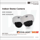
Indoor Dome IR Camera
DWC-D3361WTIR

2
PRECAUTIONS
Do not open or modify.
Do not open the case except during maintenence and installation,
for it may be dangerous and can cause damages.
Do not put objects into the unit.
Keep metal objects and flammable substances from entering the camera.
It can cause fire, short-circuits, or other damages.
Be careful when handling the unit.
To prevent damages, do not drop the camera or subject it to shock or vibration.
Do not install near electric or magnetic fields.
Protect from humidity and dust.
Protect from high temperature.
Be careful when installing near the ceiling of kitchen or a boiler room,
as the temperature may rise to high levels.
Cleaning:
To remove dirt from the case, moisten a soft cloth with a soft detergent solution and wipe.
Mounting Surface:
The material of the mounting surface must be strong enough to support the camera.
FCC COMPLIANCE
This equipment has been tested and found to comply with the limits for a Class B digital device,
pursuant to part 15 of the FCC rules. These limits are designed to provide reasonable protection
against harmful interference, when the equipment is operated in a residential environment. This
equipment generates, uses, and radiates radio frequency energy; and if it is not installed and used in
accordance with the instruction manual, it may cause harmful interference to radio communications.
WARNING: Changes or modifications are not expressly approved by the manufacturer.

Table of Contents
3
TABLE OF CONTENTS
Introduction
Installation
Module OSD Menu
Troubleshooting
Warranty Information
Specifications
Features
Parts and Descriptions
Dimensions
Inside the Box
Mount Installation Instructions
Connecting to Monitors
Control Board
Adjusting the Camera Lens
4
5
6
7
8
9
10
11
13-21
22
23-24
25-26
Adjusting the Camera Angle 12

4
FEATURES*
1/3” 760H CMOS Sensor Chip (760 Horizontal Pixels)
690TVL
2.8~12mm Varifocal Auto Iris Lens
100ft Range IR with Intelligent Camera Sync
TDN (True Day & Night) with IR Cut Filter
WDR (Wide Dynamic Range)
2D DNR (2D Digital Noise Reduction)
Smear Cancelation
AGC / AWB
Easy Icon Driven OSD Menu with Built-in Joystick
Auto Sensing 24VAC/12VDC

5
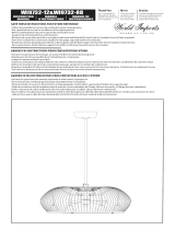
PARTS & DESCRIPTION*
1
Bottom Case
Camera Gimbal
Upper Case
Dome Cover
2
3
4
1
2
3
4

6
DIMENSIONS IN MILLIMETERS (IN)*
120.0 4.72”
9.0 0.3539.0 1.53”
89.4 3.52”
81.0 3.19”
89.0 3.50”

7
INSIDE THE BOX*
Included with your Camera
1
2
3
5
4
User Manual
Mounting Template
4 Machine Screws and 4 Dry Wall Anchors
L-Key
Secondary Video-BNC Cable
08122013
ABOUT MANUAL
Before installing and using the camera, please read this manual carefully.
Be sure to keep it handy for future reference.
Indoor Dome IR Camera
DWC-D3361WTIR

8
EASY INSTALLATION*
1. To detach the camera’s cover dome from the camera’s module
press the small buttons located at the sides of the cover dome.
While pressing the buttons, disconnect the cover dome from the
camera’s base module.
2. Use the camsera or mounting template to mark and drill the
necessary holes in the wall or ceiling.
3. Pull wires through and make connections.
4. Using the two (2) included screws, mount and secure the
camera to the wall or ceiling.
5. Adjust the camera’s Pan and Tilt. See page 12 for more
information.
6. Use the joystick to adjust the OSD menu. See pages
13-21 for more information.
7. Snap the camera’s cover dome to the camera base to complete
the installation.

Use the diagram below to connect to a Monitor or CRT Monitor properly.
12VDC/24VAC
Monitor
CCTV Monitor
Second Video Output
Power Connection - 12VDC/24VAC Dual Voltage (Auto Polarity Detection and Protection)
All cameras are equipped with a second video output for on-site configuration.
9
CONNECTING TO MONITORS*
Right
Left
Up
Down

10
Joystick: Controls the OSD menu.
Secondary Connector:
Video Output Connector for
On-Site Configuration
CONTROL BOARD*
Remotve the camera’s lens cover by rotating it counter-clockwise.
Use the Joystick to control the camera’s OSD options.
1
2

11
Follow the instructions provided below to make any lens adjustments.
ADJUSTING THE CAMERA LENS*
To adjust the field of view, use the L-Key to turn the zoom screw (located on the bottom of the
camera) counter-clockwise to zoom in, or clockwise to zoom out.
Adjust the focus the same way as descriped above AFTER the desired zoom position is established.
1
2
ZOOM
FOCUS
Non IR
IR
Zoom:
Focus:
Wide - Tele
Far - Near

12
ADJUSTING THE CAMERA GIMBAL*
1
Rotation 360º
2
Panning 360º
3
Tilting 65º
3
Tilting 55º IR LED
Non IRIR Non IR
Non IR
IR
IR

WHITE LEVEL
SYNC LEVEL
BURST
OSD GB
1 ~ 10
1 ~ 10
1 ~ 10
OFF / ON
EXIT JUMP
SAVE & EXIT / EXIT
PEDESTAL LEVEL
1 ~ 10
13
SETUP
MODULE OSD MENU*
LENS
BRIGHTNESS
AGC
LOW / MIDDLE / HIGH
WDR
EXIT JUMP
EXPOSURE COLOR
SETUPFUNCTION
WB MODE
D&N MODE
CONTRAST
2DNR
MIRROR
SHARPNESS
EXIT JUMP
SAVE & EXIT
RESTORE & EXIT
COLOR GAIN
EXIT JUMP
EXIT JUMP
MANUAL / DC
1 ~ 10
LOW / MIDDLE / HIGH
SAVE & EXIT / EXIT
ATW / INDOOR / OUTDOOR
1 ~ 10
SAVE & EXIT / EXIT
AUTO / COLOR / ETX.
SAVE & EXIT / EXIT
1 ~ 10
LEVEL1 / LEVEL2 / LEVEL3
NONE / H / V / H,V
1 ~ 10
SAVE & EXIT / EXIT
DAY & NIGHT
EXIT

14
EXPOSURE
LENS
Manual Manual mode supports the fixed board lens or the
manual iris lens.
DC DC mode supports the auto-iris varifocal lens.
BRIGHTNESS
Adjust the camera’s brightness from 0~10. The higher the
number, the brighter the image will appear.

15
EXPOSURE
WDR OFF WDR ON
WDR (Wide Dynamic Range)
Enables the camera to capture clear images even when there are both very bright and
very dark areas in the camera’s field of view. Select from the following options:
LOW / MIDDLE (Default) / HIGH.
AGC (Auto Gain Control)
AGC enhances the picture brightness in low light conditions. A higher level AGC
setting makes the images brighter; however, it could increase the amount of noise.
Set the AGC level from the following options: LOW / MIDDLE / HIGH (Default).

16
COLOR
WB MODE
ATW Set as the camera’s default value. Auto Tracking White Balance Control mode
compensates for color temperature changes between 2500K and 9500K.
OUTDOOR Select this option if the camera is to be mounted ouside in an open area.
INDOOR Select this option if the camera is to be mounted inside a closed area.
COLOR GAIN
Set the Color Gain level from 1~10.

17
DAY & NIGHT
D&N MODE
AUTO In AUTO mode, camera switches between day
and night automatically depending on light level.
COLOR If COLOR is selected, camera always stays in
day/color mode.
EXT For best IR LEDs performance, select this option
as default.
FUNCTION
CONTRAST
1~10 Set the level of contrast. The higher the contrast, the
brighter the image will appar.
The lower the contrast, the darker the image will
appear.
2D DNR (Digital Noise Reduction)
2D-DNR reduces the noise on the screen in low
light conditions and allows for clearer images,
even at night.
Select the 2D DNR level from 1~3 (Set to Level 1
as default).

18
FUNCTION
MIRROR
The mirror option allows you to flip the camera’s image horizontally and vertically to
adjust the camera’s view after installation. Chose from the following options:
NONE / H / V / H, V.
V - Flip- turns the camera upside down.
H - Flip- Mirors the camera horizonatll.
H, V - Flip- turns the camera’s image upside down and rotates is horizontally.
SHARPNESS
1 ~ 10 Sets the image sharpness. The higher the
number, the sharper the image.
V-FlipH - FlipNONE

19
SETUP
WHITE LEVEL
Adjust the camera’s White Levels from 1 ~ 10. The higher the number,
the stronger white colors in the camera’s Field of View will appear.
The camera is set by default to the optimal White Level and therefore
it is recommended not to change the original settings.
SYNC LEVEL.
Set the camera’s sync signal level value from 1 to 10.1 ~ 10.
The camera is set by default to the optimal sync signal and therefore
it is recommended not to change the original settings.
PEDESTAL LEVEL
Adjusts the camera’s Brightness Levels fom 1 ~ 10. The camera is set by
default to the optimal Pedestal Level and therefore it is recommended
not to change the original settings.

20
SETUP
BURST
Setting the color signal level value from 1 to 10.
The camera is set by default to the optimal burst level
and therefore it is recommended not to change the original settings.
OSD BG
You can add a dark background behind the OSD to better view the OSD options when the
camera’s image is too bright and the OSD text is not seen properly.
If ON is selected, a semi-transparent square will appear in the center of the camera’s display,
allowing you to better view and manage your OSD options.
/