Page is loading ...

1
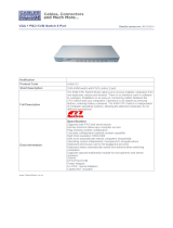
8-Port DVI KVMP Switch
with VGA support
User Manual
GCS1108 / GCS1208
PART NO. Q1207-a
www.iogear.com

2
©2012 IOGEAR. All Rights Reserved. Part No. M1207-a
IOGEAR, the IOGEAR logo, MiniView®, VSE are trademarks or registered trademarks of IOGEAR. Microsoft and Windows
are registered trademarks of Microsoft Corporation. IBM is a registered trademark of International Business Machines, Inc.
Macintosh, G3/G4 and iMac are registered trademarks of Apple Computer, Inc. IOGEAR makes no warranty of any kind
with regards to the information presented in this document. All information furnished here is for informational purposes only
and is subject to change without notice. IOGEAR. assumes no responsibility for any inaccuracies or errors that may appear
in this document.

3
Table of Contents
Introduction 4
Package Contents 5
System Requirements 5
Overview 6
Foot Pad Set Installation 7
Rack Mounting 7
Console Monitor Connection Options 9
Single Level Installation 10
2-Level Installation (Cascading) 12
3-Level Installation (Cascading) 13
Multiview installation 14
Port LED Indication 15
Port Switching 15
Port ID Numbering 15
On-screen Display (OSD) Operation 16
Hotkey Port Control 33
Hotkey Summary Table 38
Mac Keyboard Emulation 39
Sun Keyboard Emulation 39
Factory Default Settings 40
Firmware Upgrade 40
Upgrade Fail 43
Restore Factory Default Settings 44
Federal Communications Commission (FCC) Statement 45
CE Compliance 45
SJ/T 11364-2006 45
Limited Warranty 46
Contact 46

4
Introduction
The IOGEAR 8-port USB DVI KVMP Switch is a control unit that allows access and control
of up to 8 computers from a single USB keyboard, USB mouse, and dual-monitor (DVI-I and
VGA) console.
Major features for GCS1108 are:
• One USB console controls eight DVI or VGA computers
• Supports both digital (DVI), analog (DVI) video and analog (VGA)
• Superior video quality: 1920x1200 (Single Link DVI), 2048x1536 (VGA); DDC2
• Supports widescreen resolutions
• Multiplatform support – Windows, Linux, Mac, Sun
• Computer selection via front panel pushbuttons, hotkeys, and on-screen display (OSD)
• Includes two USB 2.0 peripheral sharing ports
• Independent switching of KVM and USB focus
• Two-level (Administrator / User) password authorization for enhanced security protection
• Cascadable to three levels – control up to 512 computers
• IOGEAR's DynaSync* technology reads and remembers the monitor's parameters
(EDID) so there is no delay or change of video resolution when switching between, or
booting computers
• Audio enabled – Full bass response provides a rich experience for 2.1 channel surround
sound systems
• Complete keyboard emulation for error-free booting
• Console mouse port emulation/bypass feature supports most mouse drivers and
multifunction mice
• Mac / Sun keyboard support and emulation**
• Auto Scan Mode for monitoring all computers
• Broadcast mode – allows you to send commands from the console to all computers to
perform operations simultaneously
• Firmware upgradable
• HDCP compatible
• Console audio ports on front panel for easy access
GCS1208 is a step up from GCS1108, with the support for Dual Link DVI solution, it
supports 2560 x 1600 (dual link DVI), 1920 x 1200 (single link DVI), and 2048 x 1536 (VGA).
*IOGEAR’s DynaSync provides the EDID support for Windows 7
**Note: PC keyboard combinations emulate Mac / Sun keyboards; Does not emulate Mac /
Sun keyboard to PC keyboard

5
System Requirements
Recommended Console
• Display Option #1 – A display with both DVI and VGA connection*
• Display Option #2 – A DVI-I Display
• Display Option #3 – One each of DVI and VGA displays
• 1 set of USB keyboard and mouse
Computers
• 1 DVI port or 1 VGA port
• 1 USB port
Operating Systems
• Windows XP, Windows Vista (32-bit / 64-bit)
• Windows 7 (32-bit / 64-bit)**
• Mac OS X v10.3.9 or later
• Sun Solaris
• Linux
*IOGEAR recommends Display Option #1 for the best display conguration
**IOGEAR's Display Emulation Technology provides the EDID support for Windows 7
Cable
Only custom USB DVI or VGA KVM cable sets, which are specically designed to work with
this switch, may be used to link to the computers. Two cable sets are provided with this
package.
Note: The quality of the display is affected by the quality and length of the cables. If you need
additional cable sets, please contact your dealer to purchase the appropriate ones for your switch.
Package Contents
1 x 8-port USB DVI KVMP Switch
2 x Custom USB DVI-D KVM Cable Sets
1 x Firmware Upgrade Cable
1 x Power Adapter
1 x Foot Pad Set (4 pcs)
1 x User Manual
1 x Rack Mount Kit
1 x Warranty Card
Type Length Part Number
USB DVI-D Single Link
6ft (1.8m) G2L7D02U
10ft (3.0 m) G2L7D03U
16ft (5.0 m) G2L7D05U
USB DVI-I Single Link*
6ft (1.8 m) G2L7D02UI *
10ft (3.0 m) G2L7D03UI
*For cascading setup, IOGEAR recommends to use USB DVI-I Single Link cable
(G2L7D02UI) for GCS1108, and G2L7D02UD for GCS1208.
Type Length Part Number
USB DVI-D Dual Link
6ft (1.8m) G2L7D02UD
10ft (3.0 m) G2L7D03UD
16ft (5.0 m) G2L7D05UD
USB VGA Cable 6ft (1.8m) G2L5102U
DVI-A Adapter GDVIMVGAF

8-Port USB DVI KVM Switch
AUTO SCAN K/M RESET
1
2 3 4 5 6 7 8
6
1
5 4 23
2
1
34
5
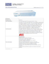
Overview
Front view
1. Port 1~8 switch Button
2. Power LED
3. Reset Button
4. USB Sharing Port
5. Firmware Upgrade Recovery Switch
Back view
1. Powe Jack
2. CPU 1 - 8 Port
3. Console Port
4. Grounding
5. Firmware upgrade Port

Step 1
Remove the screws from the left and right sides of the switch (2 screws total) near the front
of the switch.
8-Port USB DVI KVM Switch
AUTO SCAN
K/M RESET
1
2
3
4
5
6
7
8
7
Foot Pad Set Installation
Flip the KVM switch upside down. Peel the protective lms off of the foot pads, then stick the
pads to the four corners, as shown in the diagram below.
Rack Mounting

8-Port USB DVI KVM Switch
AUTO SCAN
K/M RESET
1
2
3
4
5
6
7
8
Step 2
Use the M3 x 8 Phillips hex head screws supplied with the rack mounting kit to screw the
rack mounting brackets into the sides near the front of the unit.
Final Step
Place the KVM switch in the rack. Position it so that the holes in the mounting brackets line
up with the holes in the rack. Secure the mounting brackets to the front of the rack.
8-Port USB DVI KVM Switch
AUTO SCAN
K/M RESET
1
2
3
4
5
6
7
8
8

(a) One DVI monitor (DVI-I connector)
One DVI monitor (DVI-I) – plug your DVI
console monitor into the DVI console port
located on the unit’s rear panel;
(b) One DVI monitor (DVI-D + VGA connectors)
One DVI (DVI-D + VGA) monitor – plug your
dual-interface console monitor into both the
DVI and VGA console ports
(c) Two Monitors (1 x DVI-D; 1 x VGA)
Two Monitors (1 x DVI-D; 1 x VGA) – plug
your DVI monitor into the DVI console port,
and plug your VGA monitor into the VGA
console port.
9
DVI-I
DVI-D + VGA
DVI-D
VGA
Console Monitor Connection Options

8-Port USB DVI KVM Switch
AUTO SCAN K/M RESET
1
2 3 4 5 6 7 8
10
1
2
3
Single Level Installation
1. Plug your USB keyboard and USB mouse into the USB console ports located on the
unit’s rear panel.
2. Depending on your console monitor’s interface, connect your monitor using one of the
following methods (see Console Monitor Connection Options, page 9), and power
on:
Note: Both GCS1108 and GCS1208 support DVI, VGA, and dual interface monitors, but
only one video signal (DVI or VGA) can be displayed at a time – the signal will display on
either the DVI monitor or the VGA monitor, depending on the OSD settings.
See Set Computer Viedo Input, page 28 for details about setting the correct video
input and output for your video requirements.
a. One DVI monitor (DVI-I) – plug your DVI console monitor into thhe DVI console
port located on the unit’s rear panel;
b. One DVI (DVI-D + VGA) monitor – plug your dual-interface console monitor into
both the DVI and VGA console ports;
c. Two Monitors (1 x DVI; 1 x VGA) – plug your DVI monitor into the DVI console
port, and plug your VGA monitor into the VGA console port.
3. Plug your main microphone and speakers into the console microphone and speaker jacks
located on the unit’s front panel. The microphone and speakers plugged into this panel
have priority over those in the rear panel.

11
4
6
5
8
7
4. Plug your secondary microphone and speakers into the console audio ports located on
the unit’s rear panel.
5. Using the custom USB DVI KVM cable set provided with this package, plug the DVI
connector into any available DVI socket in the KVM port section of the switch, then plug
the accompanying USB and audio connectors into their corresponding USB, microphone,
and speaker sockets.
6. At the other end of the cable, plug the USB, video, microphone, and speaker cables into
their respective ports on the computer.
7. Plug your USB peripherals into the type A sockets in the USB hub section.
8. Plug the power adapter that came with your switch into an AC power source, then plug
power adapter cable into the switch’s Power Jack.
Note: Verify that all the plugs
are in the same KVM Port
sockets (all in Port 1, all in
Port 2, etc.).
9. Turn on the power to the computers.

12
2-Level Installation (Cascading)
To control even more computers, additional 8-port DVI KVMs can be cascaded from the
KVM ports of the First Stage unit. The cascaded DVI KMVs that connect back to the First
Stage unit are considered Second Stage units. As many as 64 computers can be controlled
in a complete two stage installation.
Note: Plug the USB Type A connector into the upper USB port in the Console section
(they are both marked with a similar icon to remind you of the correct USB port).
To set up a two stage installation, refer to the Two Stage Installation diagram on the next
page as you do the following:
1. Make sure that power to all the devices you will be connecting up, including all preexisting
devices on the installation, have been turned off.
2. Use a custom USB DVI-I (G2L7D02UI) KVM cable set (see Cables, page 5), to connect any
available KVM Port on the First Stage unit to the Console ports of the Second Stage unit.
3. Using another custom USB DVI KVM cable set (provided with this package), plug the
DVI connector into any available DVI socket in the KVM port section of the switch, then
plug the accompanying USB Type A, microphone and speaker connectors into their
corresponding USB, microphone, and speaker sockets.
Note: Verify that all the plugs are in the same KVM Port sockets (all in Port 1, all in Port 2,
etc.), and that each socket is marked with an appropriate icon to indicate itself.
4. At the other end of the cable, plug the USB Type B, video, microphone, and speaker
cables into their respective ports on the computer.
5. Repeat steps 3 and 4 for any other computers you are connecting up.
6. For each Second Stage unit, plug the power adapter cable into its Power Jack, then plug
the power adapter into an AC source.
7. Plug the First Stage unit's power adapter cable into its Power Jack, then plug the power
adapter into an AC source.
8. Turn on the power to all the computers.
Note: The Power On sequence requires that all Second Stage units be powered on rst.
After all the Second Stage units have been powered on, then the First Stage unit must
be powered on next. After the Second and First stage units have been powered on, the
computers can be powered on.

13
3-Level Installation (Cascading)
The procedures for setting up a three stage installation are essentially the same as for a two
stage installation. With a three stage setup, as many as 512 computers can be controlled in
a complete installation.
Note: Switches cannot be cascaded beyond the third level.
Once you have nished cabling up, power up according to the following sequence:
1. For each Third Stage unit, plug the power adapter cable into the switch's Power Jack;
plug the power adapter into an AC source
2. For each Second Stage unit, plug the power adapter cable into the switch's Power Jack;
plug the power adapter into an AC source.
3. Plug the First Stage unit's power adapter cable into its Power Jack, then plug the power
adapter into an AC source.
4. Turn on the power to all the computers.
Note: The Power On sequence requires that all Third Stage units be powered on rst.
After they are all on, the Second Stage units must be powered on next. After all the
Second Stage units are on, the First Stage unit must be powered on. Only after all the
switches have been powered on in this sequence, can the computers be powered on.

CPU 8 CPU 7 CPU 6 CPU 5 CPU 4 CPU 3 CPU 2 CPU 1
CPU 8
CPU 7
CPU 6
CPU 5
CPU 4 CPU 3 CPU 2
CPU 1
USB Type A to
Type B cable
............................................
Computer with 2
video output
4
DVI Cables
Third / Fourth Stage Units
First Switch
Second Switch
4
1
2
3
5
14
Multiview installation
GCS1108 and GCS1208 have a very unique feature which is to support multiple video out
installations, up to 4 video out, recommended only for the DVI installations.
The multiview installation is achieved by stacking multiple GCS1108s or GCS1208s together
with different cabling (different from the usual cascading), at the same time cascading is
disabled. Because the unique cabling requires using port #8 on the KVM, the multiview
installation is limited to support maximum 7 computers.
Below is an example of a dual view DVI installation because each computer has 2 DVI
outputs. This installation requires one additional USB A-B cable, a DVI cable, and two
pieces of either GCS1108 or GCS1208 depending on the resolution of the video outs from
the computers. This allows you to view both video outs when you switch from computer to
computer. The installation procedure is as follows:
1. Use the USB A-B cable to connect the USB port of the #8 CPU port of the 1st level
KVM to the console USB port of the 2nd level KVM;
2. Use the recommended DVI KVM cable to connect the computer’s primary DVI port,
USB and audio ports, to the corresponding CPU port on the 1st level KVM (the drawing
is using port #5 as an example);
3. Use the DVI cable to connect the secondary DVI port on the computer to the
corresponding DVI port of the 2nd level KVM (Note: only DVI port is connected on the
2nd level KVM). In the example below, the DVI cable connects #5 computer’s secondary
DVI port, to the #5 DVI port on the 2nd level KVM;
4. Connect the rst DVI monitor and the rest of the console devices such as keyboard and
mouse to the console ports of the 1st level KVM;
5. Connect the 2nd DVI monitor to the DVI console port of the 2nd level KVM;
6. Power on all KVMs then power on all computers.
If your computers have 3 or 4 DVI video outs, repeat the procedure above by adding one or
two more KVMs.

15
Port LED Indication
LED Description
No LED No computer is connected to the specic port or the computer
is connected to the specic port but it is not powered on
Orange The specic port has a computer connected and it is powered
on, but does not focus on the KVM
Green The specic port has focus on the KVM
Port Switching
Port ID Numbering
There are 3 ways to switch ports on GCS1108 and GCS1208:
1. Port Switching via Front Panel Switch Button - simply press the specic push button
to switch the focus to the specic port
2. Port Switching via On-Screen Display (OSD) - please refer to OSD Operation sectio
3. Port Switching via Hotkey - please refer to Hotkey Setting Mode (HSM) section.
Add mutliview instalation
Each port on this KVM installation is assigned with a unique Port ID. You can directly
access any computer on any level of installation by specifying the Port ID that the
computer is connected to, either with the OSD or Hotkey method.
A computer attached to the rst level KVM has a two digit Port ID. For example 03 would
refer to the computer connected to the port #3 on the KVM.
A computer attached to the 2nd level cascaded KVM has a four digit Port ID. For
example, 03-08 would refer to the computer connected to the port #8 on the 2nd level
KVM which is connected to the port #3 of the 1st level KVM.
A computer attached to the 3rd level cascaded KVM has a six digit PORT ID. For
example, 03-02-07 would refer to the computer connected to the port #7 on 3rd level
KVM which is connected to the port #2 of the 2nd level KVM, which connected to the port
#3 of the 1st level KVM.

OSD Main Screen
After the log in, a screen similar to the one
at right appears:
1. The diagram depicts the administrator’s
main screen. The user main screen
does not show the F4 and F6 functions
because these are reserved for the
administrator and can’t be accessed by
users.
2. The OSD always starts in list view, with
the highlight bar at the same position it
was in the last time it was closed.
3. Only the ports that have been set
accessible by the administrator for the
current logged in user are visible.
4. If there is a next to the monitor icon,
which means that port is attached to
another KVM (Cascading). Click on a
switch number, or move the highlight
bar to it then press the right arrow key
to expand the list. Similarly, to collapse
a switch’s port list, click on the switch
number, or move the highlight bar to it
then press the left arrow key to collapse
the list.
One Level Main OSD Screen
Cascading 2nd Main OSD Screen
Cascading 2nd level screen
16
Trigger OSD
Simply press [Scroll Lock] [Scroll Lock] rapidly.
Note: This hotkey sequence can be changed to [Ctrl] [Ctrl] for Mac users. Please refer to
Hotkey Setting Mode (HSM) section.
The OSD of GCS1108 / GCS1208 incorporates a two level (administrator and user) password
system. Before the OSD main screen displays, a login screen appears requiring a password. If
this is the rst time that the OSD is used, or if the password function has not been set, simply
press [Enter]. The OSD main screen displays in administrator mode. In this mode, you have
administrator privileges, with access to all administrator and user functions, and can set up
operations (including password authorization) as you like. If the password function has been set,
you must provide an appropriate administrator/user password in order to access the OSD.
On-screen Display (OSD) Operation
OSD Login
By default, the Login and Password are
blanks, so simply press [Enter] [Enter] to
login. If you have set a user name and
password on the KVM, simply enter them
and press enter to login.

17
OSD Main Screen Headings
Heading Description
PN This column lists the port ID numbers for all the KVM ports on the
installation. The simplest method to access a particular computer is
move the highlight bar to it then press Enter.
QV QV If a port is selected for quick view scanning an arrowhead shows in
this column.
☼
The computers that are powered on and are online will a sun symbol in
this column to indicate so
Name If a port has been given a name, its name appears in this column.
OSD Navigation
• To dismiss the menu, and deactivate OSD, click the X in the upper right corner of the OSD
window; or press [Esc].
• To log out, click F8 at the top of the main screen, or press [F8].
• To move up or down through the list one line at a time, click the up and down triangle
symbols () or use the up and down arrow keys on the keyboard. If there are more list
entries than what appears on the main screen, the screen will scroll down.
• To move up or down through the list one screen at a time, click the up and down arrow
symbols (), or use the [PgUp] and [PgDn] keys. If there are more list entries than what
appears on the main screen, the screen will scroll.
• To activate a port, double-click it, or move the highlight bar to it then press [Enter].
• After executing any action, you wiill be brought back to the menu one level above.
OSD Function
OSD functions are used to congure and control the OSD. For example, you can switch to
any port, scan selected ports, limit the list you wish to view, designate a port as a Quick View
port, create or edit a port name, or make OSD setting adjustments.
To access an OSD function:
1. Either click a function key eld at the top of the main screen, or press a function key on
the keyboard.
2. In the submenus that appear make your choice either by double-clicking it, or moving
the highlight bar to it, then pressing [Enter].
3. Press [Esc] to return to the previous menu level.
There are eight options showing on top of the OSD screen:
F1: GOTO F5: SKP
F2: LIST F6: BRC
F3: SET F7: SCAN
F4: ADM F8: LOUT

If 2 was chosen then you can go to a
specic port by entering the port ID. You
can also move the red highlight bar to the
specic port that you want to go to and
press [Enter].
18
F1: GOTO
Clicking the F1 eld or pressing [F1] activates the GOTO function. GOTO allows you to
switch directly to a port either by keying in the port's Name, or its Port ID.
This function is to let you switch to a specic port via port ID or port’s name. Keying 1 to
choose from Port Name and 2 to choose from Port Number in the yellow box locating in the
bottom of the pink bar.
F1: GOTO
If 1 was chosen, then type in the port’s
name that you want to go to and then press
[Enter]. You can also move the red highlight
bar to the specic port that you want to go
to and press [Enter].

19
F2: LIST
Function Description
All List out all ports that the administrator has set as accessible for the
current logged in user
Quick View List out only the ports that have been set as quick view ports
Powered ON List out only the ports that have been powered on
Quick View +
Powered ON
List out only the ports that have been set as quick view ports and they
have been powered on
F2: LIST
Clicking the F2 eld or pressing [F2] activates the LIST function. This function allows you to
choose a way that you wish to list the ports in the OSD display on the main screen. Simply
move the red highlight bar to the option that you wish to choose and press [Enter]. You will
see the hand symbol will be pointing at the option that you chose, then simply press [Esc] to
exit the function.

20
F3: SET
Clicking the F3 eld or pressing [F3] to
activate the SET function. There are 10
different settings within the SET section.
They are shown as follow:
OSD Hotkey
Port ID Display Position
Port ID Display Duration
Port ID Display Mode
Scan Duration
Scan-Skip Mode
Screen Blanker
Hotkey Command Mode
Hotkey
OSD Language
OSD Hotkey
This function allows you to switch the way
to trigger the hotkey between [Scroll Lock]
[Scroll Lock] and [Ctrl] [Ctrl]. Simply move the
red highlight bar to the hotkey setting that
you would like to choose and press [Enter].
Then press [Esc] to exit from this function.
F3: SET
Port ID Display Position
This function allows you to change the
position of the port ID that’s showing on the
screen as the image below. Simply change
the position by using the up, down, left and
right arrows to adjust to the place that you
want the port ID to show in the future and
press [Enter]. Then press [Esc] to exit from
this function.
Port ID Display Duration
This function allows you to change the port
ID display duration between 3 Seconds and
OFF. Simply move the red highlight bar to
the option that you would like to choose
and press [Enter]. Then, press [Esc] to exit
this function.
/