Arlec MAL535 Installation guide

Type
Installation guide

Arlec MAL535 is a compact sensor light unit that controls two floodlight bulbs for wide area illumination. Ideal for security and general purposes around the home or workplace, the MAL535 features adjustable settings for time, light level, and sensitivity, allowing you to customize its performance to your specific needs. With its weatherproof design and easy installation, the MAL535 is a reliable and versatile lighting solution for any outdoor space.

Arlec MAL535 is a compact sensor light unit that controls two floodlight bulbs for wide area illumination. Ideal for security and general purposes around the home or workplace, the MAL535 features adjustable settings for time, light level, and sensitivity, allowing you to customize its performance to your specific needs. With its weatherproof design and easy installation, the MAL535 is a reliable and versatile lighting solution for any outdoor space.

DIY simple and easy to install
Installation Instructions
IMPORTANT! PLEASE READ THESE INSTRUCTIONS CAREFULLY.
Arlec guarantees this product in accordance with the Australian Consumer Law.
Arlec also warrants to the original first purchaser of this product (“you”) from a retailer that this
product will be free of defects in materials and workmanship for a period of 12 months from the date
of purchase; provided the product is not used other than for the purpose, or in a manner not within
the scope of the recommendations and limitations, specified by Arlec, is new and not damaged at
the time of purchase, has not been subjected to abuse, misuse, neglect or damage, has not been
modified or repaired without the approval of Arlec and has not been used for commercial purposes
(“Warranty”).
If you wish to claim on the Warranty, you must, at your own expense, return the product, and provide
proof of original purchase and your name, address and telephone number, to Arlec at the address
below or the retailer from whom you originally purchased the product within 12 months from the date
of purchase.
Arlec will (or authorise the retailer to) assess any claim you may make on the Warranty in the above
manner and if, in Arlec’s reasonable opinion, the Warranty applies, Arlec will at its own option and
expense (or authorise the retailer to) replace the product with the same or similar product or repair
the product and return it to you or refund the price you paid for the product. Arlec will bear its own
expenses of doing those things, and you must bear any other expenses of claiming on the Warranty.
The Warranty is in addition to other rights and remedies you may have under a law in relation to the
product to which the Warranty relates.
Our goods come with guarantees that cannot be excluded under the Australian Consumer Law.
You are entitled to a replacement or refund for a major failure and for compensation for any other
reasonably foreseeable loss or damage. You are also entitled to have the goods repaired or replaced
if the goods fail to be of acceptable quality and the failure does not amount to a major failure.
Arlec Australia Pty. Ltd. ACN 009 322 105 (“Arlec”) gives the Warranty.
Arlec’s telephone number, address and email address are:
Customer Service: (03) 9982 5111
Building 3, 31 – 41 Joseph Street, Blackburn North, Victoria, 3130
Blackburn North LPO, P.O. Box 1065, Blackburn North, 3130
Email: custser[email protected]
Warranty
CPIN002339/2
MAL535
Series 2
movement activated
security twin floodlight
CPIN002339/2
8
The Arlec MAL535 Movement Activated Sensor Light is a compact sensor light unit. It controls two
PAR38, 150W floodlight bulbs for wide area illumination. The MAL535 can be used to provide lighting
for security and general purposes in a variety of locations around the home or workplace.
IntroductIon
Figure 1.
Locknuts
Screws and rawl plugs
for fixing Junction Box
Junction Box
0.5m cable and bayonet plug
Joint &
Clamp Screw
Lamp holders
Sensor Controls
(underside)
Weather
proofing
Seals
Sensor Head
2
SIDE VIEW
-9º
10m
(33ft)
6m
(20ft)
2.5m
(8ft)
-22º
Figure 2
Figure 3a
Figure 3b
IMPORTANT: Loosen all lock nuts and screws
on sensor and lamp holders before making
any adjustments.
NOTE: Always face control knobs on sensor
downwards to ensure correct operation.
LOCATION OF UNIT.
IMPORTANT: When mounting unit, ensure
that supply cable is held securely away from
the globes using cable clips ( not supplied).
To achieve best results for exterior use, your
Movement Activated Floodlight should be
securely mounted to a wall or eaves in close
proximity (max 300mm) to an existing bayonet
style light fitting.
For ideal operation the sensor head should
be located approx 2.5m above the area where
movement is to be sensed. This will provide the
best scanning sensitivity and detection area.
Although this product is weatherproof it is
preferable to mount your Floodlight in a
sheltered or semi-sheltered location.
To avoid damage to unit - do not aim the
sensor towards the sun.
To avoid nuisance triggering, the sensor
should be directed away from heat sources
such as BBQ’s, air conditioners, other outside
lighting, flue vents and moving cars.
Do not aim towards reective surfaces
such as smooth white walls or swimming
pools etc.
The scanning specications (10m at 180°
scan) may vary slightly depending on the
mounting height and location. (Refer Fig. 2)
The detection range of the unit may also alter
with temperature change.
Before selecting a place to install the
Floodlight, you should note that movement
across the scan area is more effective than
movement directly toward or away from
the sensor. (Refer Fig. 3A). If movement is
made walking directly towards or away from
the sensor and not across, the apparent
detection range will be substantially reduced
(Refer Fig. 3B).
Avoid locating your Floodlight in close
proximity to fluorescent light fittings or
ceiling fans on the same electrical circuit.
RFI interference may cause the Floodlight to
switch on inadvertently.
Sensor can be angled above animal height
to avoid nuisance triggering of lights
Good sensitivity
Poor sensitivity
The light must be wired to its own light switch.
Do not interconnect with other lights on the
same switch.
Arrows indicate movement of
heat source
Top view
Top view
3
CPIN002339/2
SettIng up operatIon
Figure 7
Figure 9
Figure 8
Do not overtighten or use excessive force
when adjusting sensor head or lamp holders.
Loosen lock nuts or elbow/joint screws to make
adjustment.
A. Adjust the direction of the sensor arm and
lampholders to suit the desired detection
area. Loosen lock nuts and elbow screws on
lampholder before making any adjustments.
Do not use excessive force when making
adjustments to lampholders (See Fig. 7).
B. Angle sensor slightly downward towards
the detection area. The sensor joint should
be rotated to adjust the sensor to face the
required detection area. If necessary, loosen
sensor arm joint clamp screw.
C. Angle lampholders from mounting surface
and direct them approximately downwards
away from sensor head.
D. Fit PAR38 globes and weatherproong
rubber seals- do not overtighten.
E. Ensure that globes are positioned 40mm
or more from the sensor head or mounting
surface as shown in (Fig. 8). The globes
become very hot and must not be touching
or too close to sensor head.
F. After fitting globes, tighten elbow screws and
lock nuts- do not overtighten.
Understanding the controls
Time - Time “ON” adjustment
The time “ON” control adjusts the time that
the lights will remain on after the unit has
sensed movement. To increase time, turn the
knob clockwise. To decrease, turn knob anti-
clockwise.
Lux - Light level adjustment
The “Lux” control adjusts at what level of light
the unit starts sensing at dusk. This control can
be also used for testing the unit during daylight
hours. To test unit, or operate during the day,
turn control knob all the way anti-clockwise.
Once unit has been tested the “Lux” control
should be set to approx half way, and adjusted
later if required.
Sens - Sensitivity adjustment
The Sensitivity control adjusts the level of
sensitivity of the infrared Sensor. This controls
the amount of movement that is required
to switch the lights on. With the knob set to
minimum (anticlockwise), the unit will only
detect large amounts of movement. It is
recommended that in most situations the unit
be operated with the “Sens” control set to half.
Setting the controls
1. Turn the “LUX” or light control to minimum,
turn the wall switch ON and wait for half a
minute for the control circuit to stabilise. At
this stage ensure that the time control is set to
“minimum”. The Floodlights will now switch on
and remain on for about 10 seconds.
2. Turn the “SENS” control to minimum.
3. Direct the sensor toward the desired area
to be scanned by adjusting the elbow joint
and ball joint on the sensor arm. Loosen lock
nuts and screws before attempting to adjust
sensor arms.
Elbow
screw
Sensitivity
control
Light “Lux”
Control
SENS TIME LUX
Time
control
Elbow
screw
Lock nuts
40mm
Joint & clamp screw
5
eave MountIng
InStaLLatIon
waLL MountIng
Use a similar procedure to wall mounting, but
the “TOP” marking should point towards the
outside of the eave. We suggest 2 x spring
toggle screws (not supplied) be used to mount
your Floodlight under eaves. Take care not
to damage or pierce concealed wiring with
mounting screws, particularly when mounting
under eaves.
Figure 5
Wall Mount
Figure 6
Eave Mount
connectIon to power
IMPORTANT: Be careful of electric shock
hazards. Always remember that the lights may
not switch ON during the daylight or the lights
may begin automatic OFF mode. Never touch
live areas unless the power plug is removed
or circuit breaker at main switchboard is in the
OFF position.
To connect to power, simply plug the cord
into a suitable outlet. Ensure that all
connections are protected from weather.
IMPORTANT: After mounting unit, ensure that
the cord is held securely away from contact
with the globes. Use cable clips (not supplied)
if necessary.
Select a position within 300mm or so of an
existing light fitting with a bayonet socket.
The MAL535 plugs into that light fitting, effectively
replacing that light with a sensor light.
Place the junction box over the position for
mounting and mark the screw holes. Use the
two mounting lugs on the outside of the junction
box, and ensure the “TOP” marking points
upwards. Drill suitable holes and t screws to
fix junction box to the mounting surface, again
ensuring the “TOP” marking is pointing upwards.
Figure 4
4
TOP
0.5m cable and bayonet plug
Mounting
Lugs
Rubber seal
cable entry
REAR VIEW
CPIN002339/2
operatIon
SpecIfIcatIonS
MaIntenance
reducIng detectIon area
autoMatIc Mode
ManuaL operatIon
(autoMatIc overrIde)
4. Have another person move across the centre
of the area to be scanned and slowly adjust
the “SENS” control toward maximum until
the unit senses the presence of the moving
person, causing the Floodlights to switch on.
5. Adjust time control to required setting.
6. To set the light level at which the Floodlight
automatically switches “ON” at night, turn
the “LUX” or light control from minimum to
maximum. If the Floodlight is required to
switch on earlier, e.g. dusk, simply wait for
the desired light level, then slowly turn the
“LUX” or light control towards minimum while
someone walks across the centre of the area
to be detected. When the Floodlight switches
“ON” release the “LUX” or light control knob.
You may need to make further adjustments to
achieve your ideal light level setting.
IMPORTANT: When adjusting lamp holders,
ensure that PAR38 lamps are not touching
or in close proximity to sensing unit or
connecting lead. Heat from the PAR38 lamps
may distort the sensor unit or damage the lead.
Allow 40mm minimum between sensor and
PAR38 lamps.
To avoid dust build-up and ensure proper functioning of the Arlec Floodlight wipe the sensor lens
lightly with a damp cloth every 3 months. Do not use solvents or abrasive cleaners on any part of
your Floodlight.
To reduce the 180° wide-angle detection area, stick PVC electrical tape on the left, right or both sides
of sensor lens. This will reduce 180° detection in extremities of area to be scanned. After adding PVC
tape, further adjustment to sensor direction may be necessary.
To override the automatic mode, the light must
be switched ON in the “Automatic” mode. Now
switch your wall switch OFF and back ON
within two seconds. Your Floodlight will now
stay on continuously, just like a normal light.
This override function can be selected during
daytime or night time.
To return your Floodlight to the “Automatic”
mode, switch your wall switch OFF for at least
ten seconds, then switch it on again. To switch
your Floodlight off completely, switch your wall
switch OFF.
Turn your wall switch OFF for at least five
seconds and then turn the wall switch back
ON. This will put the Floodlight into “Automatic”
mode. The unit will then start sensing after
dusk. The Floodlights will switch ON and
automatically switch OFF after the pre-set time
elapses and then only operate again when heat
movement is detected.
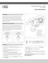
NOTE: Always tilt sensor unit head below
horizontal for weather proofing
Figure 10
TOP
Detection Range 10 metres at 180° scan
Time Adjustment 5 seconds to 8 minutes (approx.)
Detection Circuitry Passive controlled
infra red motion sensor
Power Required
(Sensor head only)
230-240 volt, 50Hz, 4 watt
consumption(Sensor head only)
Maximum Load 2 × 150 watt PAR3
Weatherproof Rating IP44
probLeM poSSIbLe cauSe SuggeSted reMedy
Light does not switch ON when there
is movement in the detection area.
1. No mains voltage. Check all connections, and fuses/switches.
2. Globe(s) faulty or missing. Check. Replace.
3. Nearby lighting is too bright. Redirect sensor or relocate unit.
4. Controls set incorrectly. Refer to Step 6 in instructions.
5. Sensor positioned in wrong direction. Re-locate sensor (Refer Fig. 3).
Light switches ON for
no apparent reason.
1. Heat from globe activating sensor. Adjust lamp holders to allow a gap between
globe and sensor lens.
2 Heat sources such as aircon. vents,
heater flues, barbecues, other outside
lighting, moving cars are activating sensor.
Adjust sensitivity. Reduce detection area of
lens using PVC tape.
3. Animals/birds e.g. possums or
domestic animals.
Probably unavoidable but redirecting
sensor may help.
4. Interference from on/off switching
of electric fans or lights on the same
circuit as your Sensor Floodlight. (This
problem does not always occur but a
faulty switch or noisy fluorescent light
may cause the Sensor Floodlight to
switch on.)
Should the false triggering become trouble-
some, consider:
(A) Replacing a faulty switch.
(B) Replacing noisy fluorescent tubes and/
or starters.
(C) Connecting the Sensor Floodlamp
to a separate circuit.(In most cases
where one or more of the above sug-
gestions have been carried out, false
triggering has been reduced.)
5. Reflection from swimming pool or
reflective surface.
Redirect sensitivity.
6. Interference from power surges, mobile
phones, CB’s, Taxis, etc.
Try reducing sensitivity.
Light remains ON. 1. Wall switch is in override “ON” mode. Switch light OFF for at least 10 seconds,
then return to ON position.
2 Time adjustment is set too long. Reduce time by turning ON-TIME control
anti-clockwise.
Lights switch ON during
daylight hours.
Daylight sensor switch is set to “OFF”
position.
Turn light level control clockwise.
When setting controls in daylight the
detection distance becomes shorter.
Interference by sunlight. Re-test at night.
NOTE: All passive infrared detectors are more sensitive in cold weather than warm weather and more
sensitive at night than daytime.
troubLe ShootIng guIde
6 7
CPIN002339/2
  • Page 1 1
  • Page 2 2
  • Page 3 3
  • Page 4 4

Arlec MAL535 Installation guide

Type
Installation guide

Arlec MAL535 is a compact sensor light unit that controls two floodlight bulbs for wide area illumination. Ideal for security and general purposes around the home or workplace, the MAL535 features adjustable settings for time, light level, and sensitivity, allowing you to customize its performance to your specific needs. With its weatherproof design and easy installation, the MAL535 is a reliable and versatile lighting solution for any outdoor space.

Ask a question and I''ll find the answer in the document

Finding information in a document is now easier with AI