Page is loading ...

Note: Electrical wiring must be carried out
by a registered electrical contractor.
Ensure electricity is switched off at the mains
before installing or maintaining any light fitting
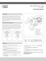
Where to fit your Arlec Dual Floodlight
with Sensor
Ideally the light should be mounted 2.4 metres (8ft)
above the area to be scanned (Refer Fig.1) or on
an eave.
Although this product is weatherproof it is
preferable to mount your Arlec Dual Floodlight with
Sensor in a sheltered or semi-sheltered location.
To avoid damage to unit – do not
aim the sensor
towards the sun.
Fig. 1
Best
sensitivity
Sensor can be angled above
animal height to avoid
nuisance triggering
Installation Instructions
Dual Floodlight with Sensor
Important! Please read these instructions carefully.
MAL413
To avoid nuisance triggering, the sensor should be
directed away from heat sources such as barbecues,
airconditioners, other outside lighting, flue vents and
moving cars.
Do not aim towards reflective surfaces such as
smooth white walls, swimming pools etc.
The scanning specifications (15 metres at 110° scan)
may vary slightly depending on the mounting height
and location. (Refer Fig. 1 and 2). The detection range
of the unit may also alter with temperature change.
Before selecting a place to install the Arlec Dual
Floodlight with Sensor, you should note that
movement across the scan area is more effective
than movement directly toward or away from the
sensor. (Refer Fig. 3A).
If movement is made walking directly towards or
away from the sensor and not across, the apparent
detection range will be substantially reduced
(Refer Fig. 3B).
3m (10ft)15m (55ft) 6m (20ft)
-6°
-27°0°
2.4m (8ft)
Ideal
mounting
height
110°
Fig. 2
Fig. 3A
Fig. 3B
Reduced
sensitivity

Installation
Installation and wiring must be performed by
a licensed electrician.
The light must be wired to its own light switch.
Do not interconnect with other lights on the
same switch.
Step 1.
Wall Mounting
Align mounting plate over desired mounting position
(as shown in Fig. 5) and mark screw holes.
Eave Mounting
For under eave installation, the sensor head must be
rotated to ensure correct operation of the Floodlight
(Refer Fig. 6).
Position the Floodlight under eaves to
allow sensor to be directed towards the area to be
scanned. Mark mounting holes through mounting
plate.
Do not overtighten or use excessive force when
adjusting sensor head or lampholders.
The sensor head must face as shown
(see Fig. 6 and 7).
Mounting plate
Joint & clamp screw
Sensor head
Screws & rawl plugs
Locknuts
Weatherproofing
seals
Lampholders
Mounting holes
Horizontal
Eave mount
Wall mount
Fig. 4
Fig. 5
Fig. 6
Fig. 7

Step 2.
Wiring
Your Floodlight must be wired to its own switch.
For installation/maintenance purposes the electrical
supply must be isolated at the switchboard by
removing the fuse or switching the circuit breaker
OFF. Simply isolating the electrical supply at the wall
switch is not sufficient isolation to prevent an
electrical shock.
There are two wires coming from the rear of the
unit, the blue must be wired to the neutral and the
brown to active, using suitable terminals. Internal
connections between the sensor and lampholders
are prewired.
An earth/ground connection is not necessary on this
product.
Step 3.
After wiring, fit Floodlight on wall or under eave
using screws supplied, or other appropriate fittings.
Take care not to damage or pierce concealed wiring
with mounting screws, particularly when mounting
under eaves.
To maintain the weatherproof rating of the unit,
silicone sealant must be used around the mounting
surface of the base to seal and fill any irregularities
in the mounting surface.
Step 4.
A. Adjust the direction of the sensor arm and
lampholders to suit the desired detection area.
Loosen lock nuts and elbow screws on
lampholder before making any adjustments.
Do not use excessive force when making
adjustments to lampholders (See Fig. 8).
B. Angle sensor slightly downward towards the
detection area. The sensor joint should be
rotated to adjust the sensor to face the required
detection area. If necessary, loosen sensor arm
joint clamp screw.
C. Angle lampholders from mounting surface and
direct them approximately downwards away from
sensor head.
D. Fit PAR38 globes and weatherproofing rubber
seals – do not overtighten.
E. Ensure that globes are positioned 40mm or more
from the sensor head or mounting surface as
shown in (Fig. 9). The globes become very hot and
must not be touching or too close to sensor head.
F. After fitting globes, tighten elbow screws and
lock nuts – do not overtighten.
IMPORTANT: Be careful of electrical shock.
Always remember that the light may not switch ON
during daylight or the light may be in the automatic
OFF mode. Never touch live areas unless fuse is
removed or circuit breaker is in OFF position at
the switchboard main.
Step 5.
If previously removed replace fuse or return power
to circuit at switchboard then switch your light
switch ON.
Step 6. To test
Test can only be performed in dark conditions, not in
daytime. For best results and operation the following
steps must be taken:
A. Direct the sensor toward the desired area to
be scanned.
B. Turn the wall switch ON; the light will come on for
90 seconds then go OFF, provided that there is no
movement in the 110° detection area.
C. Have another person move across the center
of the area to be scanned and adjust the angle of
the sensor until the unit senses the presence of
the moving person, causing the light to switch on.
Fig. 8
Fig. 9
Lock nuts
Elbow
screw
Joint &
clamp
screw
Elbow
screw
40mm

D. Your Floodlight is now ready for use, and will
automatically operate when movement is
detected at night.
E. The wall switch must remain “ON” for
automatic operation.
Automatic Mode
Turn your wall switch OFF for at least 15 seconds
and then turn the wall switch back ON. This will
put the light into “automatic” mode. The unit will
then start sensing after dusk. The light will switch
ON and automatically switch OFF after the pre-set
time elapses and will then operate automatically
whenever heat movement is detected.
Manual Operation (Automatic Override)
To override the automatic mode, the light must be
switched ON in the Automatic mode. Now switch
your wall switch OFF and back ON within two
seconds. Your Floodlight will now stay on
continuously, just like a normal light. This override
function can be selected during nighttime only.
To return your Floodlight to the “automatic” mode,
switch your wall switch OFF for at least 15
seconds, and then switch it ON again.
To switch your Floodlight off completely, switch
your wall switch OFF.
If at any time whilst changing operating mode you
are unsure which mode the unit is in, switch OFF
for at least 15 seconds, then switch back ON,
the unit will then be in the Automatic mode.
NOTE: This highly responsive unit may occasionally
activate due to rapid environmental changes.
When first switched on allow approx. 90 seconds
warm up time for the sensor operation to settle to
normal sensitivity.
Specifications
Detection Range 15 metres at 110° scan
(approx)
Time On (fixed) 6 minutes
Detection Circuitry Passive controlled
infrared motion sensor
Power Required 230-240 volt, 50Hz,
4 watt consumption
(sensor head only)
Maximum Globes 2 x 150 watt PAR38
Weatherproof Rating IP44
Maintenance
To avoid dust build-up and ensure proper
functioning wipe the sensor lens lightly with
a damp cloth every three months. Do not use
solvents or abrasive cleaners on any part of
your Floodlight.
Reducing Detection Area
To reduce the 110° wide-angle detection area,
stick PVC electrical tape on the left, right or both
sides of sensor lens. This will reduce 110° detection
in extremities of area to be scanned. After adding
PVC tape, further adjustment to sensor direction
may be necessary.

Suggested Remedy
Check all connections, and
fuses/switches.
Check. Replace.
Re-check.
Re-direct sensor or relocate unit.
Re-direct sensor (Refer Fig. 3).
Adjust lamp holders to allow a minimum
gap of 40mm between PAR38 globe and
sensor head.
Adjust direction of sensor head away
from these sources.
Probably unavoidable but redirecting
sensor may help.
Should the false triggering become
troublesome, consider:
(A) Replacing a faulty switch.
(B) Replacing noisy fluorescent tubes
and/or starters.
(C) Connecting the Floodlight to a
separate circuit.
(In most cases where one or more
of the above suggestions have been
carried out, false triggering has
been reduced.)
Re-direct sensor.
Nil.
Re-direct sensor (Refer Fig.3).
Try re-directing sensor. Note: All passive
infra red detectors are more sensitive in
cold weather than warm weather.
Switch light OFF for at least 15 seconds,
then return to ON position.
Re-direct sensor away from trees, pools,
flues etc.
Recheck wiring.
Trouble Shooting Guide
PPrroobblleemm
Light does not switch ON
when there is movement in
the detection area.
Light switches ON for
no apparent reason.
Poor Sensitivity and range.
Light remains ON.
Possible Cause
1. No mains voltage.
2. Globe(s) faulty or missing.
3. Wiring incorrect.
4. Nearby lighting is too bright.
5. Sensor positioned in wrong direction.
1. Heat from globe activating sensor.
2. Heat sources such as aircon. vents,
heater flues, barbecues, other outside
lighting, moving cars are activating
sensor.
3. Animals/birds e.g. possums or
domestic animals.
4. Interference from on/off switching
of electric fans or lights on the same
circuit as your Floodlight. (This
problem does not always occur but
a faulty switch or noisy fluorescent
light may cause the Floodlight to
switch on.)
5. Reflection from swimming pool or
reflective surface.
6. Interference from power surges,
mobile phones, CB’s, Taxis, etc.
1. Movement directly to or away from
sensor
2. Higher ambient temperature
1. Sensor is in Manual Mode.
2. Sensor is continuously triggered.
3. Wiring is incorrect.
Should a problem still exist after following all of the above user hints, contact your place of purchase.
Note: Passive infra red detectors are more sensitive in cold weather than warm weather.

For all Sales and Service enquiries
Phone (03) 9727 8860 Fax 1300 350 650
CPIN104/3
Sales and Service enquiries in New Zealand and the
South Pacific contact PDL Industries Ltd.
New Zealand: Phone 0800 735 746 Fax 0800 863 297
Fiji: Phone +679 323 5344 Fax +679 397 973
Papua New Guinea: Phone +675 323 5344 Fax +675 323 5340
All other South Pacific: Phone +64 3 339 1887 Fax +64 3 339 1672
© This instruction leaflet is subject to copyright and must not be reproduced,
copied or otherwise used in any way or for any purpose without the consent
in writing of the owner, Arlec Australia limited (A.C.N. 003 118 787).
Arlec Guarantee
Arlec guarantees this product against defects of materials
and workmanship for a period of 1 year from the date of
purchase provided that the product is used in accordance
with Arlec’s recommendations and within such voltage and
current limits as are specified by Arlec in relation to the
product. Arlec will at its own option make good, replace
with the same or similar product, or provide credit for any
product manufactured or supplied by it, which proves to be
defective within the limits set out above provided that no
repairs, alterations or modifications to the product have
been undertaken or attempted, other than by the company
or its authorised agents. Should the purchaser wish to make
a claim under the guarantee, the product should be
returned pre-paid to the place of purchase. This guarantee
is in addition to and does not take away from any rights
available to the consumer under the Trade Practices Act
and the State consumer protection legislation.
Proof of Purchase
Please retain your purchase receipt for all
warranty claims.
/