Page is loading ...

User's Guide
SLAU287A–December 2009–Revised May 2010
TAS5630PHD2EVM
This user’s guide describes the operation of the evaluation module for the TAS5630 300W Stereo
Feedback Analog-Input Digital Amplifier from Texas Instruments. The user’s guide also provides
measurement data and design information including the schematic, BOM, and PCB layout.
Contents
1 Overview ..................................................................................................................... 3
1.1 TAS5630PHD2EVM Features .................................................................................... 4
1.2 PCB Key Map ...................................................................................................... 5
2 Quick Setup Guide .......................................................................................................... 5
2.1 Electrostatic Discharge Warning ................................................................................. 5
2.2 Unpacking the EVM ................................................................................................ 6
2.3 Power Supply Setup ............................................................................................... 6
2.4 Applying Input Signal .............................................................................................. 6
2.5 Speaker Connection ............................................................................................... 7
2.6 Output configuration BTL and PBTL ............................................................................ 7
3 Protection .................................................................................................................... 7
3.1 Short-Circuit Protection and Fault-Reporting Circuitry ........................................................ 8
3.2 Fault Reporting ..................................................................................................... 8
4 TAS5630PHD2EVM Performance ........................................................................................ 8
4.1 THD+N vs Power (BTL –4 Ω) ................................................................................... 10
4.2 THD+N vs Power (BTL –8 Ω) ................................................................................... 10
4.3 THD+N vs Power (PBTL –2 Ω) ................................................................................. 11
4.4 THD+N vs Frequency (BTL –4 Ω) .............................................................................. 11
4.5 THD+N vs Frequency (BTL –8 Ω) .............................................................................. 12
4.6 THD+N vs Frequency (PBTL –2 Ω) ............................................................................ 12
4.7 FFT Spectrum with –60-dBFS Tone (BTL) .................................................................... 12
4.8 FFT Spectrum With –60-dBFS Tone (PBTL) ................................................................. 13
4.9 Idle Noise FFT Spectrum (BTL) ................................................................................ 13
4.10 Idle Noise FFT Spectrum (PBTL) .............................................................................. 14
4.11 Channel Separation .............................................................................................. 15
4.12 Frequency Response (BTL) ..................................................................................... 15
4.13 Frequency Response (PBTL) ................................................................................... 16
4.14 High-Current Protection (BTL) .................................................................................. 16
4.15 High-Current Protection (PBTL) ................................................................................ 17
4.16 Pop/Click (BTL) ................................................................................................... 17
4.17 Pop/Click (PBTL) ................................................................................................. 18
4.18 Output Stage Efficiency .......................................................................................... 18
5 Related Documentation from Texas Instruments ..................................................................... 19
5.1 Additional Documentation ....................................................................................... 19
Appendix A Design Documents ............................................................................................... 20
List of Figures
1 Integrated PurePath™ Premier Pro Amplifier System ................................................................. 4
2 Physical Structure for the TAS53630PHDEVM (Approximate Layout) .............................................. 5
3 Figure 3. PBTL Mode Configuration...................................................................................... 7
PurePath is a trademark of Texas Instruments.
1
SLAU287A–December 2009–Revised May 2010 TAS5630PHD2EVM
Copyright © 2009–2010, Texas Instruments Incorporated

www.ti.com
4 THD+N vs Power (BTL – 4 Ω)........................................................................................... 10
5 THD+N vs Power (BTL –8 Ω)............................................................................................ 10
6 THD+N vs Power (PBTL –2 Ω).......................................................................................... 11
7 THD+N vs Frequency (BTL –4 Ω)....................................................................................... 11
8 THD+N vs Frequency (BTL –8 Ω)....................................................................................... 12
9 THD+N vs Frequency (PBTL –2 Ω)..................................................................................... 12
10 FFT Spectrum with –60-dBFS Tone (BTL)............................................................................. 13
11 FFT Spectrum with –60-dBFS Tone (PBTL)........................................................................... 13
12 Idle Noise FFT Spectrum (BTL) ......................................................................................... 14
13 Idle Noise FFT Spectrum (PBTL) ....................................................................................... 14
14 Channel Separation ....................................................................................................... 15
15 Frequency Response (BTL).............................................................................................. 15
16 Frequency Response (PBTL)............................................................................................ 16
17 High-Current Protection (BTL)........................................................................................... 16
18 High-Current Protection (PBTL) ......................................................................................... 17
19 Pop/Click (BTL)............................................................................................................ 17
20 Pop/Click (PBTL) .......................................................................................................... 18
21 Output Stage Efficiency................................................................................................... 18
List of Tables
1 TAS5630PHD2EVM Specification ........................................................................................ 3
2 Recommended Supply Voltages.......................................................................................... 6
3 TAS5630 Warning/Error Signal Decoding ............................................................................... 8
4 General Test Conditions ................................................................................................... 8
5 Electrical Data............................................................................................................... 8
6 Audio Performance ......................................................................................................... 9
7 Thermal Specification ...................................................................................................... 9
8 Physical Specifications..................................................................................................... 9
9 Related Documentation from Texas Instruments ..................................................................... 19
2
TAS5630PHD2EVM SLAU287A–December 2009–Revised May 2010
Copyright © 2009–2010, Texas Instruments Incorporated

www.ti.com
Overview
1 Overview
The TAS5630PHD2EVM PurePath™ Premier Pro customer evaluation module demonstrates the
integrated circuit TAS5630PHD from Texas Instruments (TI).
The TAS5630PHD is a high-performance, integrated Stereo Feedback Analog-Input Digital Amplifier
Power Stage designed to drive 4Ω speakers at up to 300W per channel. This amplifier requires only a
simple passive demodulation filter to deliver high-quality, high-efficiency audio amplification.
This EVM is configured with 2 BTL channels and the possibility to apply either a single ended or a
differential analog input signal. It is also possible to configure the two BTL channels into one parallel BTL
(PBTL) channel.
The OPA1632 is a High Performance Fully Differential Audio Op Amp designed to allow operation with
single ended or differential input signals to the EVM.
This EVM is a complete stereo analog input 2 × 300 W power amplifier ready for evaluation and great
music.
Table 1. TAS5630PHD2EVM Specification
Key Parameters
Output stage supply voltage 25 V – 50 V
Number of channels 2 × BTL, 1 x PBTL
Load impedance BTL 4–8 Ω
Load impedance PBTL 2–3 Ω
Output power BTL 318 W / 4 Ω 10% THD or 180 W / 8 Ω / 10% THD
Output power PBTL 607 W / 2 Ω / 10% THD
DNR >100 dB(A)
PWM processor OPA1632
Output stage TAS5630PHD
Other features +15 V on-board switcher from PVDD supply
This document covers EVM specifications, audio performance and power efficiency measurements
graphs, and design documentation that includes schematics, parts list, layout, and mechanical design.
3
SLAU287A–December 2009–Revised May 2010 TAS5630PHD2EVM
Copyright © 2009–2010, Texas Instruments Incorporated

2 x AnalogInput
TAS5630PHD2EVM
MODULE
PowerSupply
2 Channel
SpeakerOutput
+12
Control
VFanOut
Overview
www.ti.com
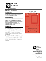
1.1 TAS5630PHD2EVM Features
• Stereo PurePath™ Premier Pro evaluation module.
• Self-contained protection system (short circuit and thermal).
• Standard 1VRMS single ended line input or differential input.
• Double-sided, plated-through PCB layout.
Figure 1. Integrated PurePath™ Premier Pro Amplifier System
4
TAS5630PHD2EVM SLAU287A–December 2009–Revised May 2010
Copyright © 2009–2010, Texas Instruments Incorporated

RESET
(SW11)
+50V
(J15)
LEFT BTL
SPEAKER
OUTPUT
(J11)
RIGHT BTL
SPEAKER
OUTPUT
(J13)
(SW1)
OUTPUT STAGE
CHANNEL RIGHT
PBLT
SERight
Input
(J21)
(SW2)
BTL PBTL BTL PBTL
OUTPUT STAGE
CHANNEL LEFT
PBTL Mode
Input
Signal
.:
SELeft
Input
(J20)
www.ti.com
Quick Setup Guide
1.2 PCB Key Map
Physical structure for the TAS5630PHD2EVM is illustrated in Figure 2.
Figure 2. Physical Structure for the TAS53630PHDEVM (Approximate Layout)
2 Quick Setup Guide
This chapter describes the TAS5630PHD2EVM board in regards to power supply and system interfaces.
The chapter provides information regarding handling and unpacking, absolute operating conditions, and a
description of the factory default switch and jumper configuration.
This section provides a step–by–step guide to configuring the TAS5630PHD2EVM for device evaluation
2.1 Electrostatic Discharge Warning
Many of the components on the TAS5630PHD2EVM are susceptible to damage by electrostatic discharge
(ESD). Customers are advised to observe proper ESD handling precautions when unpacking and handling
the EVM, including the use of a grounded wrist strap at an approved ESD workstation.
CAUTION
Failure to observe ESD handling procedures may result in damage to EVM
components.
5
SLAU287A–December 2009–Revised May 2010 TAS5630PHD2EVM
Copyright © 2009–2010, Texas Instruments Incorporated

+15V
(J17)
+50V
(J15)
JUMPER1 JUMPER2
RESET
(SW11)
DIFFINPUT
(J24)
+ 12VFAN
OUT
CONTROL
(J22)
SERight
Input
(J21)
+12VFAN
Regulator
+12VFAN
Regulator
SELeft
Input
(J20)
DIFFINPUT
(J25)
Quick Setup Guide
www.ti.com
2.2 Unpacking the EVM
On opening the TAS5630PHD2EVM package, ensure that the following items are included:
• 1 pc. TAS5630PHD2EVM board using one TAS5630PHD.
• 1 pc. PurePath CD-ROM.
If any of the items are missing, contact the Texas Instruments Product Information Center nearest you to
inquire about a replacement.
2.3 Power Supply Setup
To power up the EVM, one power supply are needed. An onboard switched voltage regulator is supplying
system power, logic and gate-drive. Power supply is connected to the EVM using connector J15.
NOTE: While powering up set switch SW11 to the RESET position.
Table 2. Recommended Supply Voltages
Description Voltage Limitations Current Requirement Cable
Output stage power supply 25 – 50 V 16 A J15 (marked +50V)
CAUTION
Applying voltages above the limitations given in Table 2 may cause permanent
damage to your hardware
NOTE: The length of power supply cable must be minimized. Increasing length of PSU cable is
equal to increasing the distortion for the amplifier at high output levels and low frequencies.
2.4 Applying Input Signal
It is possible to apply either a single ended input signal to J20 and J21 or a differential input signal to J24
and J25.
NOTE: If a single ended input signal is applied please insert jumpers in the header J24 and J25.
6
TAS5630PHD2EVM SLAU287A–December 2009–Revised May 2010
Copyright © 2009–2010, Texas Instruments Incorporated

RESET
(SW11)
+50V
(J15)
LEFT BTL
SPEAKER
OUTPUT
(J11)
RIGHT BTL
SPEAKER
OUTPUT
(J13)
(SW1)
OUTPUT STAGE
CHANNEL RIGHT
PBLT
SERight
Input
(J21)
(SW2)
BTL PBTL BTL PBTL
OUTPUT STAGE
CHANNEL LEFT
PBTL Mode
Input
Signal
.:
SELeft
Input
(J20)
www.ti.com
Protection
2.5 Speaker Connection
CAUTION
Both positive and negative speaker outputs are floating and may not be
connected to ground (e.g., through an oscilloscope).
2.6 Output configuration BTL and PBTL
When changing mode e.g. from BTL to PBTL make sure that RESET switch (SW11) is activated before
changing the state of mode switches SW1 and SW2. Switch SW1 and SW2 has to be synchronized in
state BTL or PBTL.
Input signal to RCA connector J20 when operating PBTL mode. J21 is disabled.
In PBTL mode, the load has to be connected according to :
Figure 3. Figure 3. PBTL Mode Configuration
3 Protection
This section describes the short-circuit protection and fault-reporting circuitry of the TAS5630 device.
7
SLAU287A–December 2009–Revised May 2010 TAS5630PHD2EVM
Copyright © 2009–2010, Texas Instruments Incorporated

TAS5630PHD2EVM Performance
www.ti.com
3.1 Short-Circuit Protection and Fault-Reporting Circuitry
The TAS5630 is a self-protecting device that provides fault reporting (including high-temperature
protection and short-circuit protection). The TAS5630 is configured in back-end auto-recovery mode, and
therefore; resets automatically after all errors (M1, M2, and M3 is set low); see the data sheet (SLES220)
for further explanation. This mean that the device restart itself after an error occasion and report through
the SD error signal.
3.2 Fault Reporting
The OTW and SD outputs from TAS5630 indicate fault conditions. See the TAS5630 data manual for a
description of these pins.
Table 3. TAS5630 Warning/Error Signal Decoding
SD OTW1 OTW2 Device Condition
0 0 0 High-temperature error and/or high-current error
0 0 1 Undervoltage lockout or high current error. 100°C
temperature warning.
0 1 1 Undervoltage lockout or high-current error
1 0 0 125°C temperature warning
1 0 1 100°C temperature warning
1 1 1 Normal operation, no errors/warnings
The shutdown signals together with the temperature warning signal give chip-state information as
described in the Table 3. device fault-reporting outputs are open-drain outputs.
4 TAS5630PHD2EVM Performance
Table 4. General Test Conditions
General Test Conditions Notes
Output stage supply voltage: 50 V Laboratory power supply (EA-PS 7065-10A)
Load impedance BTL: 4 and 8 Ω
Load impedance PBTL: 2 Ω
Input signal 1 kHz sine
Input configuration Unbalanced and Grounded
Measurement filter AES17 and AUX0025
Note: These test conditions are used for all tests, unless otherwise specified.
Table 5. Electrical Data
Electrical Data Notes/Conditions
Output power, BTL, 4 Ω: 260 W 1 kHz, 1% THD+N, T
A
= 25°C
Output power, BTL, 4 Ω: 315 W 1 kHz, 10% THD+N, T
A
= 25°C
Output power, BTL, 8 Ω: 145 W 1 kHz, 1% THD+N, T
A
= 25°C
Output power, BTL, 8 Ω: 180 W 1 kHz, 10% THD+N, T
A
= 25°C
Output power, PBTL, 2 Ω: 500 W 1 kHz, 1% THD+N, T
A
= 25°C
Output power, PBTL, 2 Ω: 600 W 1 kHz, 10% THD+N, T
A
= 25°C
Maximum peak current, BTL: >16.5 A 1-kHz burst, 1 Ω, R
OC
= 22 kΩ
Maximum peak current, PBTL: >33.5 A 1-kHz burst, 1 Ω, R
OC
= 22 kΩ
Output stage efficiency: >87% 2 x channels, 4 Ω
Damping factor BTL: 42 1 kHz, -3dBFS input, relative to 4 Ω load
Damping factor PBTL: 40 1 kHz, -3dBFS input, relative to 2 Ω load
Supply current: 65 mA 1 kHz, input grounded
Idle power consumption: <3.5 W Supply, input grounded
8
TAS5630PHD2EVM SLAU287A–December 2009–Revised May 2010
Copyright © 2009–2010, Texas Instruments Incorporated

www.ti.com
TAS5630PHD2EVM Performance
Table 6. Audio Performance
Audio Performance Notes/Conditions
THD+N, BTL, 4 Ω: 1 W <0.05 % 1 kHz
THD+N, BTL, 4 Ω: 10 W <0.09 % 1 kHz
THD+N, BTL, 4 Ω: 50 W <0.05 % 1 kHz
THD+N, BTL, 4 Ω: 100 W <0.4 % 1 kHz
THD+N, BTL, 4 Ω: 200 W <0.05 % 1 kHz
THD+N, BTL, 8 Ω: 1 W <0.09 % 1 kHz
THD+N, BTL, 8 Ω: 10 W <0.05 % 1 kHz
THD+N, BTL, 8 Ω: 50 W <0.05 % 1 kHz
THD+N, BTL, 8 Ω: 100 W <0.05 % 1 kHz
THD+N, PBTL, 2 Ω: 1 W <0.09 % 1 kHz
THD+N, PBTL, 2 Ω: 10 W <0.05 % 1 kHz
THD+N, PBTL, 2 Ω: 100 W <0.05 % 1 kHz
THD+N, PBTL, 2 Ω: 200 W <0.09 % 1 kHz
THD+N, PBTL, 2 Ω: 300 W <0.09 % 1 kHz
THD+N, PBTL, 2 Ω: 400 W <0.04 % 1 kHz
Dynamic Range: >102 dB Ref: rated power, A-weighted, AES17 filter, 2 ch avg
Noise Voltage: 280 mVrms A-weighted, AES17 filter
Channel Separation: >84 dB 1 kHz,
Frequency Response: +0.5 / –0.6 dB 90 W / 4 Ω, unclipped (1% THD+N)
Table 7. Thermal Specification
Thermal Specification** T
HEATSINK
* Notes/Conditions
Idle, all channels switching 30°C 1 kHz, 15 min, input grounded, T
A
= 25°C
2 x 37.5 W, 4 Ω (1/8 power) 40°C 1 kHz, 1 hour, T
A
= 25°C
2 x 300 W, 4 Ω 85°C 1 kHz, 5 min, T
A
= 25°C
*Measured on surface of heatsink
** During the thermal test the heat sink has been ventilated with a fan (NMB-MAT Type: 2410ML-04W-B50) connected to J22.
Table 8. Physical Specifications
Physical Specifications Notes/Conditions
PCB dimensions: 90 × 140 × 55 Width × Length × Height (mm)
Total weight: 400 gr Components + PCB + Heatsink + Mechanics
Note: All electrical and audio specifications are typical values.
9
SLAU287A–December 2009–Revised May 2010 TAS5630PHD2EVM
Copyright © 2009–2010, Texas Instruments Incorporated

0.01
10
0.02
0.05
0.1
0.2
0.5
1
2
5
100m 300200m 500m 1 2 5 10 20 50 100 200
Power-W
THD+N-TotalHarmonicDistortion+Noise-%
0.01
10
0.02
0.05
0.1
0.2
0.5
1
2
5
100m 300200m 500m 1 2 5 10 20 50 100 200
Power-W
THD+N-TotalHarmonicDistortion+Noise-%
TAS5630PHD2EVM Performance
www.ti.com
4.1 THD+N vs Power (BTL –4 Ω)
Figure 4. THD+N vs Power (BTL – 4 Ω)
4.2 THD+N vs Power (BTL –8 Ω)
Figure 5. THD+N vs Power (BTL –8 Ω)
10
TAS5630PHD2EVM SLAU287A–December 2009–Revised May 2010
Copyright © 2009–2010, Texas Instruments Incorporated

0.01
10
0.02
0.05
0.1
0.2
0.5
1
2
5
100m 600200m 500m 1 2 5 10 20 50 100 200
Power-W
THD+N-TotalHarmonicDistortion+Noise-%
0.01
10
0.02
0.05
0.1
0.2
0.5
1
2
5
20 20k50 100 200 500 1k 2k 5k 10k
1W
10W
200W
THD+N-TotalHarmonicDistortion+Noise-%
f-Frequency-Hz
www.ti.com
TAS5630PHD2EVM Performance
4.3 THD+N vs Power (PBTL –2 Ω)
Figure 6. THD+N vs Power (PBTL –2 Ω)
4.4 THD+N vs Frequency (BTL –4 Ω)
Figure 7. THD+N vs Frequency (BTL –4 Ω)
11
SLAU287A–December 2009–Revised May 2010 TAS5630PHD2EVM
Copyright © 2009–2010, Texas Instruments Incorporated

0.01
10
0.02
0.05
0.1
0.2
0.5
1
2
5
20 20k50 100 200 500 1k 2k 5k 10k
1W
10W
200W
THD+N-TotalHarmonicDistortion+Noise-%
f-Frequency-Hz
0.01
10
0.02
0.05
0.1
0.2
0.5
1
2
5
20 20k50 100 200 500 1k 2k 5k 10k
THD+N-TotalHarmonicDistortion+Noise-%
f-Frequency-Hz
1W
10W
300W
TAS5630PHD2EVM Performance
www.ti.com
4.5 THD+N vs Frequency (BTL –8 Ω)
Figure 8. THD+N vs Frequency (BTL –8 Ω)
4.6 THD+N vs Frequency (PBTL –2 Ω)
Figure 9. THD+N vs Frequency (PBTL –2 Ω)
4.7 FFT Spectrum with –60-dBFS Tone (BTL)
Reference voltage is 28.3 V. FFT size 16k.
12
TAS5630PHD2EVM SLAU287A–December 2009–Revised May 2010
Copyright © 2009–2010, Texas Instruments Incorporated

-150
0
-140
-130
-120
-110
-100
-90
-80
-70
-60
-50
-40
-30
-20
-10
0 22k2k 4k 6k 8k 10k 12k 14k 16k 18k 20k
f-Frequency-Hz
FFT-Spectrum-dB
0 22k2k 4k 6k 8k 10k 12k 14k 16k 18k 20k
f-Frequency-Hz
-150
0
-140
-130
-120
-110
-100
-90
-80
-70
-60
-50
-40
-30
-20
-10
FFT-Spectrum-dB
www.ti.com
TAS5630PHD2EVM Performance
Figure 10. FFT Spectrum with –60-dBFS Tone (BTL)
4.8 FFT Spectrum With –60-dBFS Tone (PBTL)
Reference voltage is 28.3 V. FFT size 16k.
Figure 11. FFT Spectrum with –60-dBFS Tone (PBTL)
4.9 Idle Noise FFT Spectrum (BTL)
Input grounded – Reference voltage is 28.3 V. FFT size 16k.
13
SLAU287A–December 2009–Revised May 2010 TAS5630PHD2EVM
Copyright © 2009–2010, Texas Instruments Incorporated

10k 80k20k 30k 40k 50k 60k 70k
f-Frequency-Hz
-140
5
-135
-125
-115
-105
-95
-85
-75
-65
-55
-45
-35
-25
-15
-5
IdleNoiseFFT-Spectrum-dB
10k 80k20k 30k 40k 50k 60k 70k
f-Frequency-Hz
-140
5
-135
-125
-115
-105
-95
-85
-75
-65
-55
-45
-35
-25
-15
-5
IdleNoiseFFT-Spectrum-dB
TAS5630PHD2EVM Performance
www.ti.com
Spurious tone at 52 kHz has it’s origin from the TL2575 switching voltage regulator.
Figure 12. Idle Noise FFT Spectrum (BTL)
4.10 Idle Noise FFT Spectrum (PBTL)
Input grounded – Reference voltage is 28.3 V. FFT size 16k.
Spurious tone at 52 kHz has it’s origin from the TL2575 switching voltage regulator.
Figure 13. Idle Noise FFT Spectrum (PBTL)
14
TAS5630PHD2EVM SLAU287A–December 2009–Revised May 2010
Copyright © 2009–2010, Texas Instruments Incorporated

-120
10
-110
-100
-90
-80
-70
-60
-50
-40
-30
-20
-10
+0
20 20k50 100 200 500 1k 2k 5k 10k
f-Frequency-Hz
ChannelSeparation-dB
RightChannel
LeftChannel
-3
3
-2.6
-2.2
-1.8
-1.4
-1
-0.6
-0.2
0.2
0.6
1
1.4
1.8
2.2
2.6
20 20k50 100 200 500 1k 2k 5k 10k
6 W
4 W
8 W
Bandwidth-dB
f-Frequency-Hz
www.ti.com
TAS5630PHD2EVM Performance
4.11 Channel Separation
Left channel input signal is set corresponding to max unclipped output power (1% THD+N) Right channel
input is grounded. Reference voltage 28.3 Vrms.
Figure 14. Channel Separation
4.12 Frequency Response (BTL)
Measurement bandwidth filter 80 kHz.
Figure 15. Frequency Response (BTL)
15
SLAU287A–December 2009–Revised May 2010 TAS5630PHD2EVM
Copyright © 2009–2010, Texas Instruments Incorporated

-3
3
-2.6
-2.2
-1.8
-1.4
-1
-0.6
-0.2
0.2
0.6
1
1.4
1.8
2.2
2.6
20 20k50 100 200 500 1k 2k 5k 10k
Bandwidth-dB
f-Frequency-Hz
8 W
6 W
3 W
2 W
-20
20
-18
-16
-14
-12
-10
-8
-6
-4
-2
0
2
4
6
8
10
12
14
16
18
24 2624.2 24.4 24.6 24.8 25 25.2 25.4 25.6 25.8
t-Time-ms
PeakCurrent- A
TAS5630PHD2EVM Performance
www.ti.com
4.13 Frequency Response (PBTL)
Measurement bandwidth filter 80 kHz.
Figure 16. Frequency Response (PBTL)
4.14 High-Current Protection (BTL)
Input 1-kHz bursted signal, load 1 Ω.
Figure 17. High-Current Protection (BTL)
16
TAS5630PHD2EVM SLAU287A–December 2009–Revised May 2010
Copyright © 2009–2010, Texas Instruments Incorporated

-40
40
-35
-30
-25
-20
-15
-10
-5
0
5
10
15
20
25
30
35
24 2624.2 24.4 24.6 24.8 25 25.2 25.4 25.6 25.8
t-Time-ms
PeakCurrent- A
0
-10
-30
-20
-40
-50
-60
-70
-80
-90
-100
-110
-120
-130
-140
20 50
100
200
500
1k
2k 5k
10k
20k
f-Frequency-Hz
Pop/ClickBTL -dB
www.ti.com
TAS5630PHD2EVM Performance
4.15 High-Current Protection (PBTL)
Input 1-kHz bursted signal, load 1 Ω.
Figure 18. High-Current Protection (PBTL)
4.16 Pop/Click (BTL)
Input grounded. The measurement results are presented in frequency domain.
Figure 19. Pop/Click (BTL)
17
SLAU287A–December 2009–Revised May 2010 TAS5630PHD2EVM
Copyright © 2009–2010, Texas Instruments Incorporated

0
-10
-20
-30
-40
-50
-60
-70
-80
-90
-100
-110
-120
-130
-140
20 50 100 200 500 1k 2k 5k 10k 20k
f-Frequency-Hz
Pop/ClickPBTL -dBv
0
100
5
10
15
20
25
30
35
40
45
50
55
60
65
70
75
80
85
90
95
0 60050 100 150 200 250 300 350 400 450 500 550
2CHOUTPUTPOWER-W
Efficiency-%
8 W
4 W
TAS5630PHD2EVM Performance
www.ti.com
4.17 Pop/Click (PBTL)
Input grounded. The measurement results are presented in frequency domain.
Figure 20. Pop/Click (PBTL)
4.18 Output Stage Efficiency
Efficiency is tested with 2 BTL channels.
The heat sink has been ventilated with a fan during the test.
Figure 21. Output Stage Efficiency
18
TAS5630PHD2EVM SLAU287A–December 2009–Revised May 2010
Copyright © 2009–2010, Texas Instruments Incorporated

www.ti.com
Related Documentation from Texas Instruments
5 Related Documentation from Texas Instruments
Table 9 contains a list of data manuals that have detailed descriptions of the integrated circuits used in the
design of the TAS5630PHD2EVM. The data manuals can be obtained at the URL http://www.ti.com.
Table 9. Related Documentation from
Texas Instruments
Part Number Literature Number
TAS5630 SLES220
OPA1632D SBOS286
LM317M SLVS297
TL2575HV-15I SLVS638
5.1 Additional Documentation
1. System Design Considerations for True Digital Audio Power Amplifiers application report (SLAA117)
2. Digital Audio Measurements application report (SLAA114)
3. PSRR for PurePath Digital™ Audio Amplifiers application report (SLEA049)
4. Power Rating in Audio Amplifiers application report (SLEA047)
5. PurePath Digital™ AM Interference Avoidance application report (SLEA040)
6. Click and Pop Measurements Technique application report (SLEA044)
7. Power Supply Recommendations for DVD-Receivers application report (SLEA027)
8. Implementation of Power Supply Volume Control application report (SLEA038)
19
SLAU287A–December 2009–Revised May 2010 TAS5630PHD2EVM
Copyright © 2009–2010, Texas Instruments Incorporated

www.ti.com
Appendix A Design Documents
This appendix comprises design documents pertaining to the TAS5162DDV6EVM evaluation module. The
documents are presented in the following order.
• Schematic (4 pages)
• Parts List (1 pages)
• PCB Specification (1 page)
• PCB Layers (6 pages)
• Heat-Sink Drawing (1 page)
20
Design Documents SLAU287A–December 2009–Revised May 2010
Copyright © 2009–2010, Texas Instruments Incorporated
/