Digi-Pas®
Installation and Operation Guidelines for
DWL4200XY and DWL4500XY
Compact Sensor Modules
Rev. 1.0.0
www.digipas.com

Digi-Pas®
© 2023 Digipas Technologies Inc. All Rights Reserved.
www.digipas.com
TOC 1
DWL-4x000XY DATA SHEET
1. Introduction ............................................................................................................................... 1
1.1. Overview ............................................................................................................................. 1
1.2. Technical Specication ......................................................................................................1
1.3. Dimension of the Compact Sensor Module ....................................................................2
2. Conguration .............................................................................................................................. 2
2.1. Conguration of Compact Sensor Module(s) with Control Box ....................................2
2.1.1. Connection using USB through Digi-Pas Control Box ..........................................3
2.1.2. Connection using Bluetooth through Digi-Pas Control Box ...............................4
2.1.3. Connection using serial converter (RS485) ..........................................................4
2.1.4. Connection using serial converter (RS232) ..........................................................7
2.2. Conguration of Single Compact Sensor Module with Converter .............................10
2.2.1. Conguration Setup Procedure (RS485) ............................................................10
3. Operation ..................................................................................................................................11
3.1. Installation of the DWL4X00XY Pc Sync Software ..........................................................11
3.2. Activating DWL4x000XY PC Sync Software ....................................................................11
3.3. Operation of Single Compact Sensor Module with Converter ...................................12
3.4. Operation of Compact Sensor Module(s) with Control Box ........................................ 13
4. Dynamic-Link Libraries For DWL4X00XY Compact Inclination Sensor Module Notes .......15
4.1. Introduction .......................................................................................................................15
4.2. DLL for Serial Communication Protocol Direct to Sensor ............................................15
4.2.1. Using the DWL4200XY Dynamic Link Library .......................................................16
4.2.1.1. DWL4200XYLibrary.SerialComm.Serial_Initialization ........................................ 16
4.2.1.2. DWL4200XYLibrary.SerialComm.Mode_Direct ............................................... 16
CONTENT

Digi-Pas®
© 2023 Digipas Technologies Inc. All Rights Reserved.
www.digipas.com
TOC 2
DWL-4x000XY DATA SHEET
4.2.1.3. DWL4200XYLibrary.SerialComm.Stand.... ........................................................ 17
4.2.1.4. DWL4200XYLibrary.SerialComm.Dual_X_Value .............................................. 17
4.2.1.5. DWL4200XYLibrary.SerialComm.Dual_Y_Value ............................................. 17
4.2.1.6. DWL4200XYLibrary.SerialComm.Vibro_Value ................................................ 17
4.2.1.7. DWL4200XYLibrary.SerialComm.Single_Alt_Zero_Value ................................ 18
4.2.1.8. DWL4200XYLibrary.SerialComm.Dual_X_Alt_Zero_Value .............................. 18
4.2.1.9. DWL4200XYLibrary.SerialComm.Dual_Y_Alt_Zero_Value .............................. 18
4.2.2. Using the DWL4500XY Dynamic Link Library ..................................................... 18
4.2.2.1. DWL4500XYLibrary.SerialComm.Serial_Initialization ....................................... 18
4.2.2.2. DWL4500XYLibrary.SerialComm.Mode_Direct. .............................................. 19
4.2.2.3. DWL4500XYLibrary.SerialComm.set_location ................................................. 20
4.2.2.4. DWL4500XYLibrary.SerialComm.Stand ............................................................ 20
4.2.2.5. DWL4500XYLibrary.SerialComm.Dual_X_Value .............................................. 20
4.2.2.6. DWL4500XYLibrary.SerialComm.Dual_Y_Value .............................................. 20
4.2.2.7. DWL4500XYLibrary.SerialComm.Vibro_Value ................................................. 21
4.2.2.8. DWL4500XYLibrary.SerialComm.Single_Alt_Zero_Value ................................ 21
4.2.2.9. DWL4500XYLibrary.SerialComm.Dual_X_Alt_Zero_Value .............................. 21
4.2.2.10. DWL4500XYLibrary.SerialComm.Dual_Y_Alt_Zero_Value ............................ 22
4.3. DLL for Serial Communication Protocol for Digi-Pas Control Box ....................22
4.3.1. Using the DWL4200XY Dynamic Link Library ............................................22
4.3.1.1. DWL4200XYLibrary.SerialComm.Serial_Initialization ............................. 23
4.3.1.2. DWL4200XYLibrary.SerialComm.Mode ................................................. 23
4.3.1.3. DWL4200XYLibrary.SerialComm.Stand .................................................. 24
4.3.1.4. DWL4200XYLibrary.SerialComm.Sensor_Connection_Status .............. 24
4.3.1.5. DWL4200XYLibrary.SerialComm.Dual_X_Value .................................... 24
4.3.1.6. DWL4200XYLibrary.SerialComm.Dual_Y_Value .................................... 24
4.3.1.7. DWL4200XYLibrary.SerialComm.Vibro_Value ....................................... 24
4.3.1.8. DWL4200XYLibrary.SerialComm.Single_Alt_Zero_Value ...................... 25

Digi-Pas®
© 2023 Digipas Technologies Inc. All Rights Reserved.
www.digipas.com
TOC 3
DWL-4x000XY DATA SHEET
4.3.1.9. DWL4200XYLibrary.SerialComm.Dual_X_Alt_Zero_Value .................... 25
4.3.1.10. DWL4200XYLibrary.SerialComm.Dual_Y_Alt_Zero_Value .................. 25
4.3.2. Using the DWL4500XY Dynamic Link Library ............................................25
4.3.2.1. DWL4500XYLibrary.SerialComm.Serial_Initialization ............................. 26
4.3.2.2. DWL4500XYLibrary.SerialComm.Mode ................................................. 26
4.3.2.3. DWL4500XYLibrary.SerialComm.Stand .................................................. 27
4.3.2.4. DWL4500XYLibrary.SerialComm.Sensor_Connection_Status ............. 27
4.3.2.5. DWL4500XYLibrary.SerialComm.Dual_X_Value .................................... 27
4.3.2.6. DWL4500XYLibrary.SerialComm.Dual_Y_Value ................................... 27
4.3.2.7. DWL4500XYLibrary.SerialComm.Vibro_Value ....................................... 28
4.3.2.8. DWL4500XYLibrary.SerialComm.Single_Alt_Zero_Value ...................... 28
4.3.2.9. DWL4500XYLibrary.SerialComm.Dual_X_Alt_Zero_Value .................... 28
4.3.2.10. DWL4500XYLibrary.SerialComm.Dual_Y_Alt_Zero_Value .................. 29
5. RS485/232 Serial Communication Protocol for Single DWL5x00XY Compact Sensor .......30
5.1. Serial Port Settings .............................................................................................................31
5.2. Buffer Frame Format .........................................................................................................30
5.3. Initialization Command ....................................................................................................30
5.4. Commands for Source and Destination ........................................................................31
5.5. Commands for Mode Selection ...................................................................................... 31
5.5.1. Single Axis Mode ...................................................................................................31
5.5.2. Dual Axis Mode .....................................................................................................32
5.5.3. Vibro Mode ............................................................................................................33
5.5.4. Calibration Mode .................................................................................................34
5.5.4.1. Detailed Calibration Steps ................................................................................ 35
5.5.5. Alternate Zero in Single Axis Mode .....................................................................39
5.5.6. Alternate Zero in Dual Axis Mode .......................................................................40
5.5.7. Absolute Level in Single & Dual Axis Mode Calculation ..................................41
5.5.8. Location Setting ....................................................................................................41

Digi-Pas®
© 2023 Digipas Technologies Inc. All Rights Reserved.
www.digipas.com
DWL-4x000XY DATA SHEET
6. Serial Communication Protocol for Control Box ................................................................... 42
6.1. Serial Port Settings .............................................................................................................42
6.2. Buffer Frame Format .........................................................................................................42
6.3. Commands for Source and Destination ........................................................................42
6.4. Commands for Mode Selection ...................................................................................... 43
6.4.1. Single Axis Mode ...................................................................................................43
6.4.2. Dual Axis Mode .....................................................................................................44
6.4.3. Vibro Mode ............................................................................................................45
6.4.4. Calibration Mode .................................................................................................46
6.4.4.1. Detailed Calibration Steps ................................................................................ 48
6.4.5. Alternate Zero in Single Axis Mode ..........................................................52
6.4.6. Alternate Zero in Dual Axis Mode ............................................................52
6.4.7. Relay Mode ................................................................................................53
APPENDIX 1: User Calibration ....................................................................................................... 54
APPENDIX 2 : Country & City Index ..............................................................................................55
7. Warranty .................................................................................................................................... 62

Digi-Pas®
© 2023 Digipas Technologies Inc. All Rights Reserved.
www.digipas.com
DWL-4x000XY DATA SHEET
APPLICATION DIAGRAM
Application diagram 1 - Multiple sensors
Application diagram 2 - Single Sensor

Digi-Pas®
© 2023 Digipas Technologies Inc. All Rights Reserved.
www.digipas.com
Page 1
DWL-4x000XY DATA SHEET
1. Introduction
1.1. Overview
Digi-Pas® DWL-4200XY and DWL-4500XY are the most Compact & Cost Effective models
yet of our iconic 2-Axis Inclination Sensor Modules that are specically designed to be
integrated into machine/equipment/structure with less space needed.
1.2. Technical Specication
DWL-4200XY DWL-4500XY
Dimension 67mm x 42mm x 23mm
Weight (Approx.) 350g
Measuring Range 0° ~ ±90.00° (Single-Axis)
0° ~ ±15.00° (Dual-Axis)
0° ~ ±10.000° (Single-Axis)
0° ~ ±5.000° (Dual-Axis)
Resolution 0.01°
(175 µm/M)
(0.002 in/feet)
0.001°
(18 μm/M)
(0.0002 in/feet)
Accuracy ± 0.01° at 0° to 2.00°
± 0.03° at other angles
± 0.001° at 0° to 2.000°
± 0.003° at other angles
Vibrometer 1.0g 2.0g
Input Voltage Regulated 9-30V DC
Maximum Load 150mA
Output Mode RS485
*USB, RS232, RS485 and SPDT Relay
*Wireless Bluetooth connectivity (optional)
Waterproof Rating IP65
Operating -40°C to +85°C
Storage -40°C to +85°C
Table 1. Technical specication of DWL4200XY & DWL4500XY compact sensor module
Notes:
-Product specication and appearance are subject to change for product improvement without prior notice.
-*Control Box is required
Figure 1. DWL-4200XY & DWL-4500XY Compact sensor module

Digi-Pas®
© 2023 Digipas Technologies Inc. All Rights Reserved.
www.digipas.com
Page 2
DWL-4x000XY DATA SHEET
1.3. Dimension of the Compact Sensor Module
Figure 2. DWL-4200XY & DWL 4500XY Compact Sensor Dimension
42 mm
1.65”
23 mm
0.9”
67 mm
2.64”
54 mm
2.13”
2. Conguration
This section deliberates how to congure the compact sensor module to communicate
with PC, machine or equipment. Visit https://www.digipas.com/support/video.php to
view how to use the control box with DWL-4x000XY sensor.
2.1. Conguration of Compact Sensor Module(s) with Control Box
Figure 3. Overview of the Control Box

Digi-Pas®
© 2023 Digipas Technologies Inc. All Rights Reserved.
www.digipas.com
Page 3
DWL-4x000XY DATA SHEET
Figure 4. Diagram overview of serial connection through control box using serial converter
2.1.1. Connection using USB through Digi-Pas Control Box
2.1.1.1. Materials for the Conguration
• 1 × DWL4200XY or DWL4500XY Compact sensor module
• 1 × 12V DC Power Source
• 1 × Digi-Pas control box
• 1 × USB cable
2.1.1.2. Conguration Setup Procedure
1. Connect the sensor cord to the sensor input on the Digi-Pas control box.
2. Source in regulated 12V DC to the power supply input.
3. The Power LED (PWR) of the control box lights in orange color. Once the initialization be-
tween the sensor module and the control box is completed, the Power LED turns yellow.
The Sensor LED (SEN 1, SEN 2, SEN 3, SEN 4) on the respective sensor lights up in green
color. If the connection between the tilt sensor module and control box is lost, the Power
LED lights up in red.
4. Connect the USB cable from USB2.0 Standard-B Port on the control box to the PC as
shown in Figure 5.

Digi-Pas®
© 2023 Digipas Technologies Inc. All Rights Reserved.
www.digipas.com
Page 4
DWL-4x000XY DATA SHEET
Figure 5. Diagram for USB connection through control box
5. The conguration is then completed. Users can obtain data throught PC Sync
software please refer to “3. Operation”
2.1.2. Connection using Bluetooth through Digi-Pas Control Box
2.1.2.1. Materials for the Conguration
• 1 × DWL4200XY, or DWL4500XY compact sensor module
• 1 × 12V DC Power Source
• 1 × Digi-Pas control box
2.1.2.2. Conguration Setup Procedure
1. Connect the sensor cord to the sensor input on the Digi-Pas control box.
2. Source in regulated 12V DC to the power supply input.
3. The Power LED (PWR) of the control box lights in orange color. Once the initialization be-
tween the sensor module and the control box is completed, the Power LED turns yellow.
The Sensor LED (SEN 1, SEN 2, SEN 3, SEN 4) on the respective sensor lights up in green
color. If the connection between the tilt sensor module and control box is lost, the Power
LED lights up in red.
4. The conguration is then completed. Users can obtain data through PC Sync software
please refer to “3. Operation”
2.1.3. Connection using serial converter (RS485)
2.1.3.1. Materials for the Conguration
• 1 × DWL4200XY, or DWL4500XY compact sensor module
• 1 × 12V DC Power Source

Digi-Pas®
© 2023 Digipas Technologies Inc. All Rights Reserved.
www.digipas.com
Page 5
DWL-4x000XY DATA SHEET
• 1 × Digi-Pas DWL control box
• 1 × RS485 converter In this example,
• Computer/Workstation with or without PC Sync software installed.
2.1.3.2. Conguration Setup Procedure
1. Connect the sensor cord to the sensor input on the Digi-Pas control box.
2. Source in regulated 12V DC to the power supply input for Control Box.
3. The Power LED (PWR) of the control box lights in orange color. Once the initialization be-
tween the sensor module and the control box is completed, the Power LED turns yellow.
The Sensor LED (SEN 1, SEN 2, SEN 3, SEN 4) on the respective sensor lights up in green
color. If the connection between the tilt sensor module and control box is lost, the Power
LED lights up in red.
4. Select the Serial output Switch on the control box (refer to Figure 6) to RS485.
Figure 6. Changing control box output to support RS485 connection
5. Connect the cable from RS485 serial output on the control box to converter as in gure
7.

Digi-Pas®
© 2023 Digipas Technologies Inc. All Rights Reserved.
www.digipas.com
Page 6
DWL-4x000XY DATA SHEET
Figure 7. Diagram RS485 Serial connection through control box using and serial converter to PC
6. The connection wiring pinout of the control box RS485 serial output is illustrated in
Figure 8.
Pin No. Description
1NC
2RS485 - A (Non-inverting Receiver Input/Tx+)
3RS485 - B (Inverting Receiver Input/Tx-)
4RS485 - Z (Inverting Driver Output)/Rx-)
5 RS485 - Y (Noninverting Driver Output / Rx+)
6GND
7NC
8 RS232 - Receiver Input (Rx)
9RS232 - Transmitter Output (Tx)

Digi-Pas®
© 2023 Digipas Technologies Inc. All Rights Reserved.
www.digipas.com
Page 7
DWL-4x000XY DATA SHEET
Figure 8. The connection pinout of RS485 Serial Output with ES-U-3001-M converter in RS485 mode
7. The conguration is then completed. The conguration is then completed. Users
can obtain data through PC Sync software please refer to “3. Operation”, using
Digi-Pas DLL refer to “4.2 . DLL for Serial Communication Protocol Direct to Sen-
sor” or direct programming refer to “6. Serial Communication Protocol for Control
Box”
2.1.4. Connection using serial converter (RS232)
2.1.4.1. Materials for the Conguration
• 1 × DWL4200XY or DWL4500XY compact sensor module
• 1 × 12V DC Power Source
• 1 × Digi-Pas control box.
• 1 × RS422/485 converter.
2.1.4.2. Conguration Setup Procedure
1. Connect the sensor cord to the sensor input on the Digi-Pas control box.
2. Source in regulated 12V DC to the power supply input for Control Box.
3. The Power LED (PWR) of the control box lights in orange color. Once the initialization be-
tween the sensor module and the control box is completed, the Power LED turns yellow.
The Sensor LED (SEN 1, SEN 2, SEN 3, SEN 4) on the respective sensor lights up in green
color. If the connection between the tilt sensor module and control box is lost, the Power
LED lights up in red.
4. Select the Serial output Switch on the control box (refer to Figure 9) to RS232.
Serial Output
Converter
Adapter

Digi-Pas®
© 2023 Digipas Technologies Inc. All Rights Reserved.
www.digipas.com
Page 8
DWL-4x000XY DATA SHEET
Figure 9. Changing control box output to support RS232 connection
5. Connect the cable from RS232 serial output on the control box to Custom converter as
in Figure 9.
Figure 10. Diagram RS232 Serial connection through control box using and serial converter to PC
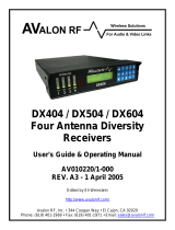
6. The connection wiring pinout of the control box RS232 serial output is illustrated in Figure
11.

Digi-Pas®
© 2023 Digipas Technologies Inc. All Rights Reserved.
www.digipas.com
Page 9
DWL-4x000XY DATA SHEET
Pin No. Description
1NC
2RS485 - A (Non-inverting Receiver Input/Tx+)
3RS485 - B (Inverting Receiver Input/Tx-)
4RS485 - Z (Inverting Driver Output)/Rx-)
5 RS485 - Y (Noninverting Driver Output / Rx+)
6GND
7NC
8 RS232 - Receiver Input (Rx)
9RS232 - Transmitter Output (Tx)
Figure 11. The connection pinout of RS232 Serial Output with Serial converter in RS232 mode
7. The conguration is then completed. The conguration is then completed. Users can
obtain data through PC Sync software please refer to “3. Operation”, using Digi-Pas DLL
refer to “4.2 . DLL for Serial Communication Protocol Through Digi-Pas Control Box” or
direct programming refer to “6. Serial Communication Protocol for Control Box”

Digi-Pas®
© 2023 Digipas Technologies Inc. All Rights Reserved.
www.digipas.com
Page 10
DWL-4x000XY DATA SHEET
2.2. Conguration of Single Compact Sensor Module without control box
2.2.1. Materials for the Conguration
• 1 × DWL4200XY or DWL4500XY compact sensor module
• 1 × RS485 converter (4 wires).
• 1 × 9~30V DC Power Source
• 1 × custom cable with DB9 (Female) connector
• Computer/Workstation with PC Sync software installed
Figure 12. Diagram for Direct Serial connection without control box using custom cable and serial converter
2.2.2. Conguration Setup Procedure (RS485)
1. Prepare the custom cable. The constructed custom cable and the pinout of the
DB9 (Female) connector is shown in Figure 13.
Pin No. Description
1GND
2N.C (No Connection)
3GND (without Control Box) or Signal 1 (For
Control Box only)
4GND (without Control Box) or Signal 2 (For
Control Box only)
5 Power Input (Regulated 9V)
6RS485 - A (Non-inverting Receiver Input/Tx+)
7RS485 - B (Inverting Receiver Input/Tx-)
8 RS485 - Z (Inverting Driver Output)/Rx-)
9RS485 - Y (Noninverting Driver Output / Rx+)
DB-9 (Female) Connector
Figure 13. Constructed custom cable and pinout of the DB9 (Female) connector

Digi-Pas®
© 2023 Digipas Technologies Inc. All Rights Reserved.
www.digipas.com
Page 11
DWL-4x000XY DATA SHEET
3. Operation
3.1. Installation of the DWL4x00XY PC Sync Software
1. DWL4200XY or DWL4500XY PC Sync Software Basic Edition available at the Digi-pas web-
site. Run the installation auto-run screen appears as in Figure 15. Click on “Windows OS 64
Bit Install Only” button to start the installation. Alternatively, DWL4200XY or DWL4500XY PC
Sync Software Basic Edition can be downloaded from https://www.digipas.com/support/
rmware.php.
2. Follow the instructions on the screen, once the installation is completed, shortcut of the
DWL4x00XY icon will be appeared in desktop as shown in Figure 15. The PC is now ready
to connect with the compact sensor module or control box.
Figure 15. Shortcut of the DWL4x00XY PC SYNC
3.2. Activating DWL4x00XY PC Sync Software
1. Launch the PC Sync Software and it will prompt for activation, select “Yes”

Digi-Pas®
© 2023 Digipas Technologies Inc. All Rights Reserved.
www.digipas.com
Page 12
DWL-4x000XY DATA SHEET
2. Fill required eld and 16-digit product key and press “Activate” to activate it.
3. Sucessfull activation will popup notication “Code Successfully Redeemed”. Your PC Sync
pro are ready to use.
3.3. Operation of Single Compact Sensor Module with Converter
4. Assuming steps stated in 3.1 Conguration of Single Compact Sensor Module with Con-
verter and 4.1 Installation of the DWL4x00XY PC Sync Software have been done in this
stage. Open PC SYNC software and select RS485 from the drop down menu as shown in
Figure 16.
5. Next, click “No” button as in Figure 17.
Figure 17. Select RS485 from the drop down menu
Figure 16. Shortcut of the DWL4x00XY PC SYNC

Digi-Pas®
© 2023 Digipas Technologies Inc. All Rights Reserved.
www.digipas.com
Page 13
DWL-4x000XY DATA SHEET
6. Select the COM port
Figure 18. COM port selection
7. Screen as illustrated in Figure 19 appears. The feature icons are enabled and ready for se-
lection (e.g. Single Angle Meter, Dual Angle Meter...). Following is an example when Single
Angle Meter feature icon is clicked.
Figure 19. Interface of the PC SYNC software with Single Angle Meter feature

Digi-Pas®
© 2023 Digipas Technologies Inc. All Rights Reserved.
www.digipas.com
Page 14
DWL-4x000XY DATA SHEET
3.4. Operation of Sensor Module(s) with Control Box
1. Assuming steps stated in 3.2 Conguration of Sensor Module(s) with Control Box and 4.1
Installation of the DWL4x00XY PC Sync Software have been done in this stage. Open PC
SYNC software and select the desired mode from the drop down menu as shown in Figure
20. In this example, RS485 is selected.
Figure 20. Select mode from the drop down menu
Figure 21. Select RS485 from the drop down menu
3. Select Discover Bluetooth Device if connection via Bluetooth
Figure 22. COM port or Bluetooth Discovery
4. Screen as illustrated in Figure 23 appears. The feature icons are enabled and ready for se-
lection (e.g. Single Angle Meter, Dual Angle Meter...). Following is an example when Single
Angle Meter feature icon is clicked.
Figure 23. Interface of the PC SYNC software with Single Angle Meter feature
Page is loading ...
Page is loading ...
Page is loading ...
Page is loading ...
Page is loading ...
Page is loading ...
Page is loading ...
Page is loading ...
Page is loading ...
Page is loading ...
Page is loading ...
Page is loading ...
Page is loading ...
Page is loading ...
Page is loading ...
Page is loading ...
Page is loading ...
Page is loading ...
Page is loading ...
Page is loading ...
Page is loading ...
Page is loading ...
Page is loading ...
Page is loading ...
Page is loading ...
Page is loading ...
Page is loading ...
Page is loading ...
Page is loading ...
Page is loading ...
Page is loading ...
Page is loading ...
Page is loading ...
Page is loading ...
Page is loading ...
Page is loading ...
Page is loading ...
Page is loading ...
Page is loading ...
Page is loading ...
Page is loading ...
Page is loading ...
Page is loading ...
Page is loading ...
Page is loading ...
Page is loading ...
Page is loading ...
Page is loading ...
/