
RabbitCore RCM3400
C-Programmable Analog Core Module
with 10/100Base-T Reference Design
User’s Manual
019–0122_P

RabbitCore RCM3400
RabbitCore RCM3400 User’s Manual
©2013 Digi International® Inc.
All rights reserved.
Rabbit, Dynamic C, Rabbit 4000, Digi, Digi International, Digi International Com-
pany, and the Digi and Rabbit logos are trademarks or registered trademarks of Digi
International, Inc. in the United States and other countries worldwide. All other trade-
marks are the property of their respective owners.
Information in this document is subject to change without notice and does not repre-
sent a commitment on the part of Digi International.
Digi provides this document "as is," without warranty of any kind, expressed or
implied, including, but not limited to, the implied warranties of fitness or merchant-
ability for a particular purpose. Digi may make improvements and/or changes in this
manual or in the product(s) and/or the program(s) described in this manual at any
time.
This product could include technical inaccuracies or typographical errors. Changes
are periodically made to the information herein; these changes may be incorporated in
new editions of the publication.
The latest revision of this manual is available at www.digi.com.

User’s Manual
TABLE OF CONTENTS
Chapter 1. Introduction 1
1.1 RCM3400 Features ...............................................................................................................................1
1.2 Advantages of the RCM3400 ...............................................................................................................3
1.3 Development and Evaluation Tools......................................................................................................4
1.3.1 RCM3400 Development Kit .........................................................................................................4
1.3.2 Software ........................................................................................................................................5
1.3.3 Connectivity Interface Kits ...........................................................................................................5
1.3.4 Online Documentation ..................................................................................................................5
Chapter 2. Getting Started 7
2.1 Install Dynamic C .................................................................................................................................7
2.2 Hardware Connections..........................................................................................................................8
2.2.1 Attach Module to Prototyping Board............................................................................................8
2.2.2 Connect Programming Cable ........................................................................................................9
2.2.3 Connect Power ............................................................................................................................10
2.2.3.1 Overseas Development Kits ............................................................................................... 10
2.3 Run a Sample Program .......................................................................................................................11
2.3.1 Troubleshooting ..........................................................................................................................11
2.4 Where Do I Go From Here? ...............................................................................................................12
2.4.1 Technical Support .......................................................................................................................12
Chapter 3. Running Sample Programs 13
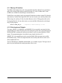
3.1 Introduction.........................................................................................................................................13
3.2 Sample Programs ................................................................................................................................14
3.2.1 Serial Communication.................................................................................................................15
3.2.2 A/D Converter Inputs..................................................................................................................17
3.2.3 Real-Time Clock .........................................................................................................................18
3.2.4 TCP/IP Sample Programs ...........................................................................................................18
3.2.5 LCD/Keypad Module Sample Programs ....................................................................................18
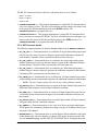
Chapter 4. Hardware Reference 19
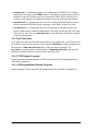
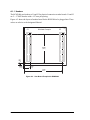
4.1 RCM3400 Digital Inputs and Outputs ................................................................................................20
4.1.1 Memory I/O Interface .................................................................................................................26
4.1.2 Other Inputs and Outputs ............................................................................................................26
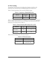
4.2 Serial Communication ........................................................................................................................27
4.2.1 Serial Ports ..................................................................................................................................27
4.2.2 Programming Port .......................................................................................................................27
4.3 Serial Programming Cable..................................................................................................................29
4.3.1 Changing Between Program Mode and Run Mode ....................................................................29
4.3.2 Standalone Operation of the RCM3400......................................................................................30

RabbitCore RCM3400
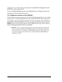
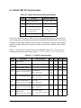
4.4 A/D Converter .................................................................................................................................... 31
4.4.1 A/D Converter Calibration ......................................................................................................... 33
4.4.2 A/D Converter Power Supply..................................................................................................... 33
4.5 Other Hardware .................................................................................................................................. 34
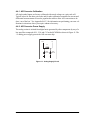
4.5.1 Clock Doubler ............................................................................................................................ 34
4.5.2 Spectrum Spreader...................................................................................................................... 34
4.6 Memory .............................................................................................................................................. 35
4.6.1 SRAM......................................................................................................................................... 35
4.6.2 Flash EPROM............................................................................................................................. 35
4.6.3 Dynamic C BIOS Source Files................................................................................................... 35
Chapter 5. Software Reference 37
5.1 More About Dynamic C..................................................................................................................... 37
5.2 Dynamic C Function Calls ................................................................................................................. 39
5.2.1 Digital I/O................................................................................................................................... 39
5.2.2 Serial Communication Drivers................................................................................................... 39
5.2.3 TCP/IP Drivers ........................................................................................................................... 39
5.2.4 Prototyping Board Function Calls .............................................................................................. 40
5.2.5 Board Initialization..................................................................................................................... 40
5.2.6 Analog Inputs ............................................................................................................................. 41
5.3 Upgrading Dynamic C ....................................................................................................................... 55
5.3.1 Upgrades..................................................................................................................................... 55
Appendix A. RCM3400 Specifications 57
A.1 Electrical and Mechanical Characteristics ........................................................................................ 58
A.1.1 Headers ...................................................................................................................................... 62
A.2 Bus Loading ...................................................................................................................................... 63
A.3 Rabbit 3000 DC Characteristics ........................................................................................................ 66
A.4 I/O Buffer Sourcing and Sinking Limit............................................................................................. 67
A.5 Conformal Coating ............................................................................................................................ 68
A.6 Jumper Configurations ...................................................................................................................... 69
Appendix B. Prototyping Board 71
B.1 Introduction ....................................................................................................................................... 72
B.1.1 Prototyping Board Features ....................................................................................................... 73
B.2 Mechanical Dimensions and Layout ................................................................................................. 75
B.3 Power Supply..................................................................................................................................... 76
B.4 Using the Prototyping Board ............................................................................................................. 77
B.4.1 Adding Other Components ........................................................................................................ 79
B.4.2 Measuring Current Draw ........................................................................................................... 79
B.4.3 Analog Features ......................................................................................................................... 80
B.4.3.1 A/D Converter Inputs........................................................................................................ 80
B.4.3.2 Thermistor Input ............................................................................................................... 82
B.4.3.3 A/D Converter Calibration................................................................................................ 83
B.4.4 Serial Communication ............................................................................................................... 84
B.4.4.1 RS-232 .............................................................................................................................. 85
B.4.4.2 RS-485 .............................................................................................................................. 86
B.4.4.3 Ethernet Port ..................................................................................................................... 88
B.4.5 Other Prototyping Board Modules............................................................................................. 89
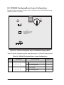
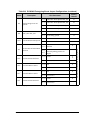
B.5 RCM3400 Prototyping Board Jumper Configurations ...................................................................... 90
Appendix C. Using the TCP/IP Features 93
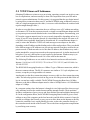
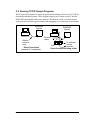
C.1 TCP/IP Connections .......................................................................................................................... 93
C.2 TCP/IP Primer on IP Addresses ........................................................................................................ 95
C.2.1 IP Addresses Explained ............................................................................................................. 97
C.2.2 How IP Addresses are Used....................................................................................................... 98
C.2.3 Dynamically Assigned Internet Addresses................................................................................ 99

User’s Manual
C.3 Placing Your Device on the Network ..............................................................................................100
C.4 Running TCP/IP Sample Programs..................................................................................................101
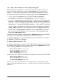
C.4.1 How to Set IP Addresses in the Sample Programs...................................................................102
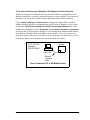
C.4.2 How to Set Up your Computer’s IP Address for Direct Connect ............................................103
C.5 Run the PINGME.C Sample Program .............................................................................................104
C.6 Running Additional Sample Programs With Direct Connect ..........................................................104
C.7 Where Do I Go From Here?.............................................................................................................105
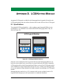
Appendix D. LCD/Keypad Module 107
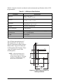
D.1 Specifications...................................................................................................................................107
D.2 Contrast Adjustments for All Boards...............................................................................................109
D.3 Keypad Labeling..............................................................................................................................110
D.4 Header Pinouts .................................................................................................................................111
D.4.1 I/O Address Assignments.........................................................................................................111
D.5 Mounting LCD/Keypad Module on the Prototyping Board ............................................................112
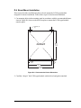
D.6 Bezel-Mount Installation .................................................................................................................113
D.6.1 Connect the LCD/Keypad Module to Your Prototyping Board...............................................115
D.7 Sample Programs .............................................................................................................................116
D.8 LCD/Keypad Module Function Calls ..............................................................................................117
D.8.1 LCD/Keypad Module Initialization .........................................................................................117
D.8.2 LEDs ........................................................................................................................................117
D.8.3 LCD Display ............................................................................................................................118
D.8.4 Keypad .....................................................................................................................................138
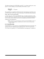
Appendix E. Power Supply 141
E.1 Power Supplies .................................................................................................................................141
E.1.1 Battery-Backup Circuits ...........................................................................................................141
E.1.2 Reset Generator ........................................................................................................................142
Index 143

RabbitCore RCM3400

User’s Manual 1
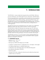
1. INTRODUCTION
The RCM3400 is a compact module that incorporates the powerful Rabbit
®
3000 micro-
processor, flash memory, static RAM, digital I/O ports, analog inputs, and PWM outputs.
The Development Kit has the essentials that you need to design your own microprocessor-
based system, and includes a complete Dynamic C software development system. This
Development Kit also contains a Prototyping Board that will allow you to evaluate the
RCM3400 and to prototype circuits that interface to the RCM3400 module. You will also
be able to write and test software for the RCM3400 modules, including Ethernet or
TCP/IP applications.
Throughout this manual, the term RCM3400 refers to the complete series of RCM3400
RabbitCore modules unless other production models are referred to specifically.
The RCM3400 has a Rabbit 3000 microprocessor operating at up to 29.4 MHz, static
RAM, flash memory, an 8-channel A/D converter, two clocks (main oscillator and time-
keeping), and the circuitry necessary for reset and management of battery backup of the
Rabbit 3000’s internal real-time clock and the static RAM. Two 34-pin headers bring out
the Rabbit 3000 I/O bus lines, parallel ports, A/D converter channels, and serial ports.
The RCM3400 receives its +3.3 V power from the customer-supplied motherboard on
which it is mounted. The RCM3400 can interface with all kinds of CMOS-compatible
digital devices through the motherboard.
1.1 RCM3400 Features
• Small size: 1.16" × 1.37" × 0.31"
(29 mm × 34 mm × 8 mm)
• Microprocessor: Rabbit 3000 running
at up to 29.4 MHz
• 47 parallel 5 V tolerant I/O lines: 41 configurable for I/O, 3 fixed inputs, 3 fixed outputs
• Two additional digital inputs, one additional digital output
• Combinations of up to eight single-ended or four differential analog inputs
• One additional analog input (CONVERT)
• External reset input
• Alternate I/O bus can be configured for 8 data lines and 6 address lines (shared with
parallel I/O lines), I/O read/write

2 RabbitCore RCM3400
• Ten 8-bit timers (six cascadable) and one 10-bit timer with two match registers
• 512K flash memory, 512K SRAM, (options for 256K flash memory and 256K SRAM)
• Real-time clock
• Watchdog supervisor
• Provision for customer-supplied backup battery via connections on header J2
• 10-bit free-running PWM counter and four width registers
• Two-channel Input Capture can be used to time input signals from various port pins
• Two-channel Quadrature Decoder accepts inputs from external incremental encoder
modules
•
Five CMOS-compatible serial ports: maximum asynchronous baud rate of 5.5 Mbps
.
Four ports are configurable as a clocked serial port (SPI), and two ports are configu-
rable as SDLC/HDLC serial ports.
• Supports 1.15 Mbps IrDA transceiver
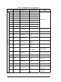
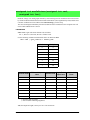
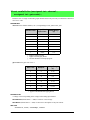
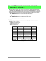
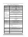
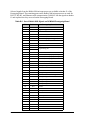
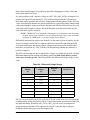
There are two RCM3400 production models. Table 1 summarizes their main features.
The RCM3400 can be programmed through connections on the motherboard supporting
RS-232, USB with an RS-232/USB converter, or over an Ethernet connection.
Appendix A provides detailed specifications for the RCM3400.
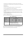
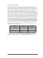
Table 1. RCM3400 Features
Feature RCM3400 RCM3410
Microprocessor Rabbit 3000 at 29.4 MHz
Flash Memory 512K 256K
SRAM 512K 256K
A/D Converter 12 bits
Serial Ports
5 shared high-speed, CMOS-compatible ports:
5 are configurable as asynchronous serial ports;
4 are configurable as clocked serial ports (SPI);
2 are configurable as SDLC/HDLC serial ports;
1 asynchronous serial port is used during programming

User’s Manual 3
1.2 Advantages of the RCM3400
• Fast time to market using a fully engineered, “ready-to-run/ready-to-program” micro-
processor core.
• Competitive pricing when compared with the alternative of purchasing and assembling
individual components.
• Easy C-language program development and debugging
• Rabbit Field Utility to download compiled Dynamic C .bin files, and cloning board
options for rapid production loading of programs.
• Generous memory size allows large programs with tens of thousands of lines of code,
and substantial data storage.
• Reference design allows integrated Ethernet port for network connectivity, with
royalty-free TCP/IP software.

4 RabbitCore RCM3400
1.3 Development and Evaluation Tools
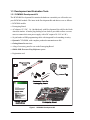
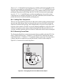
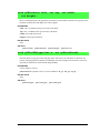
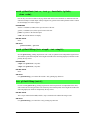
1.3.1 RCM3400 Development Kit
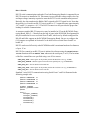
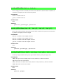
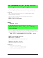
The RCM3400 Development Kit contains the hardware essentials you will need to use
your RCM3400 module. The items in the Development Kit and their use are as follows.
• RCM3400 module.
• Prototyping Board.
• AC adapter, 12 V DC, 1 A. (Included only with Development Kits sold for the North
American market. A header plug leading to bare leads is provided to allow overseas
users to connect their own power supply with a DC output of 8–24 V at 8 W.)
• 10-pin header to DB9 programming cable with integrated level-matching circuitry.
• Dynamic C CD-ROM, with complete product documentation on disk.
• Getting Started instructions.
• A bag of accessory parts for use on the Prototyping Board.
• Rabbit 3000 Processor Easy Reference poster.
• Registration card.
Figure 1. RCM3400 Development Kit
•
•
•
•
•
•
•
•
•
setup.exe

User’s Manual 5
1.3.2 Software
The RCM3400 is programmed using version 7.32 or later of Dynamic C. A compatible
version is included on the Development Kit CD-ROM.
Digi also offers add-on Dynamic C modules containing the popular C/OS-II real-time
operating system, as well as PPP, Advanced Encryption Standard (AES), and other select
libraries. In addition to the Web-based technical support included at no extra charge, a
one-year telephone-based technical support module is also available for purchase. Visit
our Web site at www.digi.com or contact your Digi sales representative or authorized dis-
tributor for further information.
1.3.3 Connectivity Interface Kits
Digi has available additional interface kits to allow you to provide a wireless interface to
the RCM3400 and to use the RCM3400 with header sockets that have a 0.1" pitch.
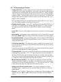
• 802.11b Wi-Fi Add-On Kit (Part No. 101-0998)—The Wi-Fi Add-On Kit for the
RCM3400 footprint consists of an RCM3400 Interposer Board, a Wi-Fi CompactFlash
card with a CompactFlash Wi-Fi Board, a ribbon interconnecting cable, and the soft-
ware drivers and sample programs to help you enable your RCM3400 module with
Wi-Fi capabilities. The RCM3400 Interposer Board is placed between the RCM3400
module and the RCM3400 Prototyping Board so that the CompactFlash Wi-Fi Board,
which holds the Wi-Fi CompactFlash card, can be connected to the RCM3400-based
system via the ribbon cable provided.
• Connector Adapter Board (Part No. 151-0114)—allows you to plug the RCM3400
whose headers have a 1.27 mm pitch into header sockets with a 0.1" pitch.
Visit our Web site at www.digi.com or contact your Digi sales representative or authorized
distributor for further information.
1.3.4 Online Documentation
The online documentation is installed along with Dynamic C, and an icon for the docu-
mentation menu is placed on the workstation’s desktop. Double-click this icon to reach the
menu. If the icon is missing, use your browser to find and load
default.htm in the docs
folder, found in the Dynamic C installation folder.
The latest versions of all documents are always available for free, unregistered download
from our Web sites as well.

6 RabbitCore RCM3400

User’s Manual 7
2. GETTING STARTED
This chapter describes the RCM3400 hardware in more detail, and explains how to set up
and use the accompanying Prototyping Board.
NOTE: This chapter (and this manual) assume that you have the RCM3400 Development
Kit. If you purchased an RCM3400 module by itself, you will have to adapt the infor-
mation in this chapter and elsewhere to your test and development setup.
2.1 Install Dynamic C
To develop and debug programs for the RCM3400 (and for all other Rabbit Semiconductor
hardware), you must install and use Dynamic C.
If you have not yet installed Dynamic C version 7.32 (or a later version), do so now by
inserting the Dynamic C CD from the RCM3400 Development Kit in your PC’s CD-ROM
drive. If autorun is enabled, the CD installation will begin automatically.
If autorun is disabled or the installation does not start, use the Windows Start | Run menu
or Windows Disk Explorer to launch setup.exe from the root folder of the CD-ROM.
The installation program will guide you through the installation process. Most steps of the
process are self-explanatory.
Dynamic C uses a COM (serial) port to communicate with the target development system.
The installation allows you to choose the COM port that will be used. The default selec-
tion is COM1. You may select any available port for Dynamic C’s use. If you are not cer-
tain which port is available, select COM1. This selection can be changed later within
Dynamic C.
NOTE: The installation utility does not check the selected COM port in any way. Speci-
fying a port in use by another device (mouse, modem, etc.) may lead to a message such
as
"could not open serial port" when Dynamic C is started.
Once your installation is complete, you will have up to three new icons on your PC desk-
top. One icon is for Dynamic C, one opens the documentation menu, and the third is for
the Rabbit Field Utility, a tool used to download precompiled software to a target system.
If you have purchased any of the optional Dynamic C modules, install them after installing
Dynamic C. The modules may be installed in any order. You must install the modules in
the same directory where Dynamic C was installed.

8 RabbitCore RCM3400
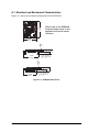
2.2 Hardware Connections
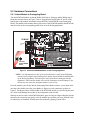
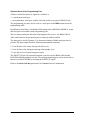
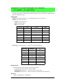
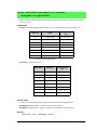
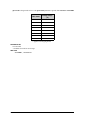
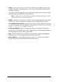
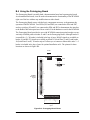
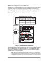
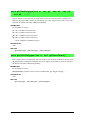
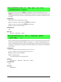
2.2.1 Attach Module to Prototyping Board
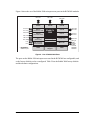
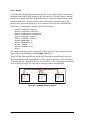
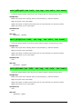
Turn the RCM3400 module so that the Rabbit 3000 chip is facing up and the Rabbit logo is
facing the direction shown in Figure 2 below. Align the pins from headers J1 and J2 on the
bottom side of the module into header sockets RCM1JA and RCM1JB on the Prototyping
Board. The shaded corner notch at the top left corner of the RCM3400 module should face the
same direction as the corresponding notch below it on the Prototyping Board.
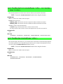
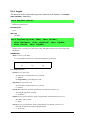
Figure 2. Install the RCM3400 Module on the Prototyping Board
NOTE: It is important that you line up the pins on headers J1 and J2 of the RCM3400
module exactly with the corresponding pins of header sockets RCM1JA and RCM1JB
on the Prototyping Board. The header pins may become bent or damaged if the pin
alignment is offset, and the module will not work. Permanent electrical damage to the
module may also result if a misaligned module is powered up.
Press the module’s pins firmly into the Prototyping Board header sockets—press down in the
area above the header pins using your thumbs or fingers over the connectors as shown in
Figure 2. Do not press down on the middle of the RCM3400 module to avoid flexing the mod-
ule, which could damage the module or the components on the module.
Should you need to remove the RCM3400 module, grasp it with your fingers along the top and
bottom by the connectors and gently work the module up to pull the pins away from the sock-
ets where they are installed. Do not remove the module by grasping it at the sides.
DCIN
R58
+5 V
+3.3 V
+3.3 V
GND
+5 V
GND
GND
+5 V
GND
GND
+3.3 V
+3.3 V
+5 V
+5 V
+5 V
GND
GND
+3.3 V
+3.3 V
S1
2
1
2
1
DS2
R57
PD7
PD4
R4
R5
R3
C2
R1
R2
R9
C6
C9
C3
C1
IR1
60
59
RS-485
JUMPER
DEFAULT (12, 56)
R26
R22
C13
U2
R21
JP3
JP8
JP4
PG6
PG7
C26
C23
CX3
CX4
CX5
CX7
CX8
CX6
CX9
CX10
CX11
RESET
1
2
R39
R40
R41
R42
R62
C31
C32
R45
C33
C34
C35
C36
C37
U7
C40
U6
R59
C47
C45
C50
C51
C49
C52
C48
C44
C42
C41
R48
C38
C49
C39
R50
R51
R53
R54
R52
R56
R55
C46
C43
Y1
J7
RS-232
J6
TxF
RxF
RxE
TxE
GND
C30
RxD
TxD
GND
R46
TxC
RxC
RS-232
J5
U5
C29
C28
C27
C24
C21
C19
U4
J4
+485 GND 485
C18
C22 C25
BT1
DS4
DS3
LINK ACT
R60
R61
CURRENT
MEASUREMENT
OPTION
JP10
DS5
POWER
R65
L1
D1
J8
D2
J9
C61
U12
C58
C57
C54
C55
U10
C56
HOT
C59
C60
U13
+BKLT
/CS
LED1
LED3
LED5
A2
A0
D1
D3
D5
D7
GND GND
LCD1J1
LCD1J2
LCD1J3
A2
A1
D1
D3
D5
D7
GND
A3
A1
D0
D2
D4
D6
GND
+V
/RESET
LDE0
LED2
LED4
LED6
GND
+BKLT
/CS
LED1
LED3
LED5
GND
GND
R64
+5 V
Battery
PA0
PA2
PA4
PA6
PB1
PB3
PB5
PB7
PC1
PC3
PC7
/IOWR
SMODE1
PD0
PD5
PD7
PE1
PE4
PE6
PF0
PF4
PF6
PG0
PG2
PG4
PG6
/RES OUT
+3.3 V
VBAT
GND
RN2
RN1
PA1
PA3
PA5
PA7
PB2
PB4
PB6
PC0
PC2
PC6
/IORD
STAT
SMD0
PD4
PD6
PE0
PE2
PE5
PE7
PF1
PF5
PF7
PG1
PG3
PG5
PG7
RESET IN
GND
+3.3 V
GND
J1
J2
PROGRAM
R6
R7
R10
C7
R16
C5
CX2
UX2
CX1
UX1
U3
RCM1J2
RCM1J1
2
34
R25
R28
R19
33
1
R67
JP6
JP7
420 mA
JP9
JP5
JP2
JP1
U1
C11
R13
R14
R29
R31
R34
R36
C8
C4
R8
R11
R12
R15
R18
R23
R27
R32
R35
R38
C10
C12
R17
C14
R20
C15
R24
C16
R30
C17
R33
C20
R37
J3
RCM3400
PROTOTYPING
BOARD
GND AIN0 AIN1 AIN2 AIN3 AIN4 AIN5 AIN6 THERM GND CNVRT VREF
S2
S3
DS1
R43
R44
PD5
PD6
R47
+V
/RES
ET
LED0
LED2
LED4
LED6
GND
A3
A1
D0
D2
D4
D6
C53
Do not
press down
here.
RCM3400
JP1
C61
C59
C56
JP2
R21
C40
C39
C33
C34
C28
U3
C22
U2
C48
C53
C51
RP2
RP3
RP4
JP3
C55
C50
R25
R24
C62
D1
C35
R20
R18
R17
R13
C32
R11
C31
Y1
U5
U7
U1
C9
C8
R1
R4
C1
C3
C4
C5
C24
C25
C19
C14
C13
C2
R3
Shaded
notch
RCM1JB
RCM1JA

User’s Manual 9
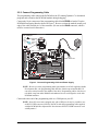
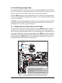
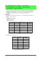
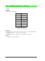
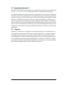
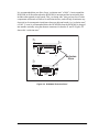
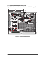
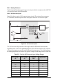
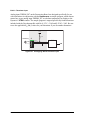
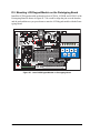
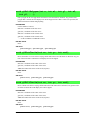
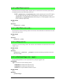
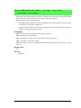
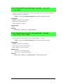
2.2.2 Connect Programming Cable
The programming cable connects the RCM3400 to the PC running Dynamic C to download
programs and to monitor the RCM3400 module during debugging.
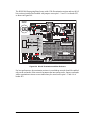
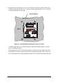
Connect the 10-pin connector of the programming cable labeled
PROG to header J2 on the
RCM3400 Prototyping Board as shown in Figure 3. Be sure to orient the marked (usually red)
edge of the cable towards pin 1 of the connector. (Do not use the
DIAG connector, which is
used for a normal serial connection.)
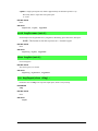
Figure 3. Connect Programming Cable and Power Supply
NOTE: Be sure to use the programming cable (part number 101-0542) supplied with this
Development Kit—the programming cable has blue shrink wrap around the RS-232
converter section located in the middle of the cable. Programming cables with clear or
red shrink wrap from other Rabbit Semiconductor kits are not designed to work with
RCM3400 modules.
Connect the other end of the programming cable to a COM port on your PC.
NOTE: Some PCs now come equipped only with a USB port. It may be possible to use
an RS-232/USB converter (Part No. 540-0070) with the programming cable supplied
with the RCM3400 Development Kit. Note that not all RS-232/USB converters work
with Dynamic C.
DCIN
R58
+5 V
+3.3 V
+3.3 V
GND
+5 V
GND
GND
+5 V
GND
GND
+3.3 V
+3.3 V
+5 V
+5 V
+5 V
GND
GND
+3.3 V
+3.3 V
S1
2
1
2
1
DS2
R57
PD7
PD4
R4
R5
R3
C2
R1
R2
R9
C6
C9
C3
C1
IR1
60
59
RS-485
JUMPER
DEFAULT (12, 56)
R26
R22
C13
U2
R21
JP3
JP8
JP4
PG6
PG7
C26
C23
CX3
CX4
CX5
CX7
CX8
CX6
CX9
CX10
CX11
RESET
1
2
R39
R40
R41
R42
R62
C31
C32
R45
C33
C34
C35
C36
C37
U7
C40
U6
R59
C47
C45
C50
C51
C49
C52
C48
C44
C42
C41
R48
C38
C49
C39
R50
R51
R53
R54
R52
R56
R55
C46
C43
Y1
J7
RS-232
J6
TxF
RxF
RxE
TxE
GND
C30
RxD
TxD
GND
R46
TxC
RxC
RS-232
J5
U5
C29
C28
C27
C24
C21
C19
U4
J4
+485 GND 485
C18
C22 C25
BT1
DS4
DS3
LINK ACT
R60
R61
CURRENT
MEASUREMENT
OPTION
JP10
DS5
POWER
R65
L1
D1
J8
D2
J9
C61
U12
C58
C57
C54
C55
U10
C56
HOT
C59
C60
U13
+BKLT
/CS
LED1
LED3
LED5
A2
A0
D1
D3
D5
D7
GND GND
LCD1JA
LCD1JB
LCD1JC
A2
A1
D1
D3
D5
D7
GND
A3
A1
D0
D2
D4
D6
GND
+V
/RESET
LDE0
LED2
LED4
LED6
GND
+BKLT
/CS
LED1
LED3
LED5
GND
GND
R64
+5 V
Battery
PA0
PA2
PA4
PA6
PB1
PB3
PB5
PB7
PC1
PC3
PC7
/IOWR
SMODE1
PD0
PD5
PD7
PE1
PE4
PE6
PF0
PF4
PF6
PG0
PG2
PG4
PG6
/RES OUT
+3.3 V
VBAT
GND
RN2
RN1
PA1
PA3
PA5
PA7
PB2
PB4
PB6
PC0
PC2
PC6
/IORD
STAT
SMD0
PD4
PD6
PE0
PE2
PE5
PE7
PF1
PF5
PF7
PG1
PG3
PG5
PG7
RESET IN
GND
+3.3 V
GND
J1
J2
PROGRAM
R6
R7
R10
C7
R16
C5
CX2
UX2
CX1
UX1
U3
RCM1JB
RCM1JA
2
34
R25
R28
R19
33
1
R67
JP6
JP7
420 mA
JP9
JP5
JP2
JP1
U1
C11
R13
R14
R29
R31
R34
R36
C8
C4
R8
R11
R12
R15
R18
R23
R27
R32
R35
R38
C10
C12
R17
C14
R20
C15
R24
C16
R30
C17
R33
C20
R37
J3
RCM3400
PROTOTYPING
BOARD
GND AIN0 AIN1 AIN2 AIN3 AIN4 AIN5 AIN6 THERM GND CNVRT VREF
S2
S3
DS1
R43
R44
PD5
PD6
R47
+V
/RES
ET
LED0
LED2
LED4
LED6
GND
A3
A1
D0
D2
D4
D6
C53
3-pin
power connector
JP1
C61
C59
C56
JP2
R21
C40
C39
C33
C34
C28
U3
C22
U2
C48
C53
C51
RP2
RP3
RP4
JP3
C55
C50
R25
R24
C62
D1
C35
R20
R18
R17
R13
C32
R11
C31
Y1
U5
U7
U1
C9
C8
R1
R4
C1
C3
C4
C5
C24
C25
C19
C14
C13
C2
R3
Colored
edge
To
PC COM port
PROG
J2
Blue
shrink wrap
PROG
DIAG
Programming
Cable

10 RabbitCore RCM3400
2.2.3 Connect Power
When all other connections have been made, you can connect power to the Prototyping Board.
Connect the wall transformer to jack J8 on the Prototyping Board as shown in Figure 3.
Plug in the wall transformer. The power LED on the Prototyping Board should light up. The
RCM3400 and the Prototyping Board are now ready to be used.
NOTE: A RESET button is provided on the Prototyping Board to allow a hardware reset
without disconnecting power.
2.2.3.1 Overseas Development Kits
Development kits sold outside North America include a header connector that may be con-
nected to 3-pin header J9 on the Prototyping Board. The connector may be attached either way
as long as it is not offset to one side. The red and black wires from the connector can then be
connected to the positive and negative connections on your power supply. The power supply
should deliver 8 V–24 V DC at 8 W.

User’s Manual 11
2.3 Run a Sample Program
If you already have Dynamic C installed, you are now ready to test your programming
connections by running a sample program. Start Dynamic C by double-clicking on the
Dynamic C icon or by double-clicking on dcrab_XXXX.exe in the Dynamic C root
directory, where XXXX are version-specific characters.
Dynamic C uses the serial port
specified during installation.
If you are using a USB port to connect your computer to the RCM3400 module, choose
Options > Project Options and select “Use USB to Serial Converter” under the
Communications tab.
Find the file PONG.C, which is in the Dynamic C SAMPLES folder. To run the program,
open it with the File menu, compile it using the Compile menu, and then run it by selecting
Run in the Run menu. The STDIO window will open on your PC and will display a small
square bouncing around in a box.
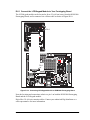
2.3.1 Troubleshooting
If you receive the message No Rabbit Processor Detected, the programming
cable may be connected to the wrong COM port, a connection may be faulty, or the target
system may not be powered up. First, check to see that the power LED on the Prototyping
Board is lit and that the jumper across pins 5–6 of header JP10 on the Prototyping Board is
installed. If the LED is lit, check both ends of the programming cable to ensure that it is
firmly plugged into the PC and the programming port on the Prototyping Board. Ensure
that the module is firmly and correctly installed in its connectors on the Prototyping
Board.
If Dynamic C appears to compile the BIOS successfully, but you then receive a communi-
cation error message when you compile and load a sample program, it is possible that your
PC cannot handle the higher program-loading baud rate. Try changing the maximum
download rate to a slower baud rate as follows.
• Locate the
Serial Options dialog in the Dynamic C Options > Project Options >
Communications
menu. Select a slower Max download baud rate.
If a program compiles and loads, but then loses target communication before you can
begin debugging, it is possible that your PC cannot handle the default debugging baud
rate. Try lowering the debugging baud rate as follows.
• Locate the Serial Options dialog in the Dynamic C Options > Project Options >
Communications
menu. Choose a lower debug baud rate.
If there are no faults with the hardware, select a different COM port within Dynamic C.
From the Options menu, select Project Options, then select Communications. Select
another COM port from the list, then click OK. Press <Ctrl-Y> to force Dynamic C to
recompile the BIOS. If Dynamic C still reports it is unable to locate the target system, repeat
the above steps until you locate the active COM port.You should receive a message Bios
compiled successfully once this step is completed successfully.

12 RabbitCore RCM3400
2.4 Where Do I Go From Here?
If the sample program ran fine, you are now ready to go on to the sample programs in the
RCM3400 User’s Manual (click the documentation icon on your PC) and to develop your
own applications. The sample programs
can be easily modified for your own use. The user's
manual also provides complete hardware reference information and software function calls for
the RCM3400, the Prototyping Board, the Ethernet reference design, and the optional
LCD/Keypad module.
For advanced development topics, refer to the Dynamic C User’s Manual and the
Dynamic C TCP/IP User’s Manual, also in the online documentation set.
2.4.1 Technical Support
NOTE: If you purchased your RCM3400 through a distributor or through a Rabbit Semi-
conductor partner, contact the distributor or partner first for technical support.
If there are any problems at this point:
• Use the Dynamic C Help menu to get further assistance with Dynamic C.
• Check the Rabbit Semiconductor Technical Bulletin Board at
http://forums.digi.com/support/formum/index.
• Use the Technical Support e-mail form at http://www.digi.com/support.

User’s Manual 13
3. RUNNING SAMPLE PROGRAMS
To develop and debug programs for the RCM3400 (and for all other Digi hardware), you
must install and use Dynamic C. This chapter provides a tour of its major features with
respect to the RCM3400.
3.1 Introduction
To help familiarize you with the RCM3400 modules, Dynamic C includes several sample
programs. Loading, executing and studying these programs will give you a solid hands-on
overview of the RCM3400’s capabilities, as well as a quick start with Dynamic C as an
application development tool.
NOTE: The sample programs assume that you have at least an elementary grasp of ANSI
C. If you do not, see the introductory pages of the Dynamic C User’s Manual for a sug-
gested reading list.
In order to run the sample programs discussed in this chapter and elsewhere in this manual,
1. Your RCM3400 must be plugged in to the Prototyping Board as described in Chapter 2,
“Getting Started.”
2. Dynamic C must be installed and running on your PC.
3. The programming cable must connect the programming header on the Prototyping
Board to your PC.
4. Power must be applied to the RCM3400 through the Prototyping Board.
Refer to Chapter 2, “Getting Started,” if you need further information on these steps.
To run a sample program, open it with the
File menu (if it is not still open), compile it
using the Compile menu (or press F5), and then run it by selecting Run in the Run menu
(or press F9). The RCM3400 must be in Program Mode (see Figure 7) and must be con-
nected to a PC using the programming cable.
More complete information on Dynamic C is provided in the Dynamic C User’s Manual.

14 RabbitCore RCM3400
3.2 Sample Programs
Of the many sample programs included with Dynamic C, several are specific to the
RCM3400. These programs will be found in the SAMPLES\RCM3400 folder.
Each sample program has comments that describe the purpose and function of the pro-
gram. Follow the instructions at the beginning of the sample program.
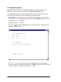
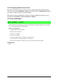
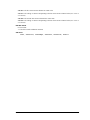
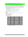
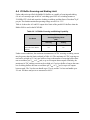
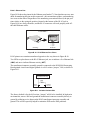
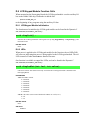
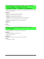
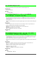
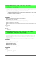
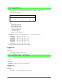
• CONTROLLED.c—Demonstrates use of the digital inputs by having you turn LEDs
DS1 and DS2 on the Prototyping Board on or off from the STDIO window on your PC.
Parallel Port D bit 6 = LED DS1
Parallel Port D bit 7 = LED DS2
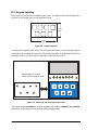
Once you compile and run CONTROLLED.C, the following display will appear in the
Dynamic C STDIO window.
Press “1” or “2” on your keyboard to select LED DS1 or DS2 on the Prototyping
Board. Then follow the prompt in the Dynamic C
STDIO window to turn the LED ON
or OFF. A logic low will light up the LED you selected.
Page is loading ...
Page is loading ...
Page is loading ...
Page is loading ...
Page is loading ...
Page is loading ...
Page is loading ...
Page is loading ...
Page is loading ...
Page is loading ...
Page is loading ...
Page is loading ...
Page is loading ...
Page is loading ...
Page is loading ...
Page is loading ...
Page is loading ...
Page is loading ...
Page is loading ...
Page is loading ...
Page is loading ...
Page is loading ...
Page is loading ...
Page is loading ...
Page is loading ...
Page is loading ...
Page is loading ...
Page is loading ...
Page is loading ...
Page is loading ...
Page is loading ...
Page is loading ...
Page is loading ...
Page is loading ...
Page is loading ...
Page is loading ...
Page is loading ...
Page is loading ...
Page is loading ...
Page is loading ...
Page is loading ...
Page is loading ...
Page is loading ...
Page is loading ...
Page is loading ...
Page is loading ...
Page is loading ...
Page is loading ...
Page is loading ...
Page is loading ...
Page is loading ...
Page is loading ...
Page is loading ...
Page is loading ...
Page is loading ...
Page is loading ...
Page is loading ...
Page is loading ...
Page is loading ...
Page is loading ...
Page is loading ...
Page is loading ...
Page is loading ...
Page is loading ...
Page is loading ...
Page is loading ...
Page is loading ...
Page is loading ...
Page is loading ...
Page is loading ...
Page is loading ...
Page is loading ...
Page is loading ...
Page is loading ...
Page is loading ...
Page is loading ...
Page is loading ...
Page is loading ...
Page is loading ...
Page is loading ...
Page is loading ...
Page is loading ...
Page is loading ...
Page is loading ...
Page is loading ...
Page is loading ...
Page is loading ...
Page is loading ...
Page is loading ...
Page is loading ...
Page is loading ...
Page is loading ...
Page is loading ...
Page is loading ...
Page is loading ...
Page is loading ...
Page is loading ...
Page is loading ...
Page is loading ...
Page is loading ...
Page is loading ...
Page is loading ...
Page is loading ...
Page is loading ...
Page is loading ...
Page is loading ...
Page is loading ...
Page is loading ...
Page is loading ...
Page is loading ...
Page is loading ...
Page is loading ...
Page is loading ...
Page is loading ...
Page is loading ...
Page is loading ...
Page is loading ...
Page is loading ...
Page is loading ...
Page is loading ...
Page is loading ...
Page is loading ...
Page is loading ...
Page is loading ...
Page is loading ...
Page is loading ...
Page is loading ...
Page is loading ...
Page is loading ...
Page is loading ...
Page is loading ...
Page is loading ...
-
 1
1
-
 2
2
-
 3
3
-
 4
4
-
 5
5
-
 6
6
-
 7
7
-
 8
8
-
 9
9
-
 10
10
-
 11
11
-
 12
12
-
 13
13
-
 14
14
-
 15
15
-
 16
16
-
 17
17
-
 18
18
-
 19
19
-
 20
20
-
 21
21
-
 22
22
-
 23
23
-
 24
24
-
 25
25
-
 26
26
-
 27
27
-
 28
28
-
 29
29
-
 30
30
-
 31
31
-
 32
32
-
 33
33
-
 34
34
-
 35
35
-
 36
36
-
 37
37
-
 38
38
-
 39
39
-
 40
40
-
 41
41
-
 42
42
-
 43
43
-
 44
44
-
 45
45
-
 46
46
-
 47
47
-
 48
48
-
 49
49
-
 50
50
-
 51
51
-
 52
52
-
 53
53
-
 54
54
-
 55
55
-
 56
56
-
 57
57
-
 58
58
-
 59
59
-
 60
60
-
 61
61
-
 62
62
-
 63
63
-
 64
64
-
 65
65
-
 66
66
-
 67
67
-
 68
68
-
 69
69
-
 70
70
-
 71
71
-
 72
72
-
 73
73
-
 74
74
-
 75
75
-
 76
76
-
 77
77
-
 78
78
-
 79
79
-
 80
80
-
 81
81
-
 82
82
-
 83
83
-
 84
84
-
 85
85
-
 86
86
-
 87
87
-
 88
88
-
 89
89
-
 90
90
-
 91
91
-
 92
92
-
 93
93
-
 94
94
-
 95
95
-
 96
96
-
 97
97
-
 98
98
-
 99
99
-
 100
100
-
 101
101
-
 102
102
-
 103
103
-
 104
104
-
 105
105
-
 106
106
-
 107
107
-
 108
108
-
 109
109
-
 110
110
-
 111
111
-
 112
112
-
 113
113
-
 114
114
-
 115
115
-
 116
116
-
 117
117
-
 118
118
-
 119
119
-
 120
120
-
 121
121
-
 122
122
-
 123
123
-
 124
124
-
 125
125
-
 126
126
-
 127
127
-
 128
128
-
 129
129
-
 130
130
-
 131
131
-
 132
132
-
 133
133
-
 134
134
-
 135
135
-
 136
136
-
 137
137
-
 138
138
-
 139
139
-
 140
140
-
 141
141
-
 142
142
-
 143
143
-
 144
144
-
 145
145
-
 146
146
-
 147
147
-
 148
148
-
 149
149
-
 150
150
-
 151
151
-
 152
152


Ask a question and I''ll find the answer in the document
Finding information in a document is now easier with AI
Related papers
-
Digi Rabbit - Peripherals and Accessory User manual
-
Digi RCM4000 User manual
-
-
Digi RCM3700 User manual
-
Digi RCM2200 User manual
-
Digi Bluetooth Application Kit User manual
-
Digi RCM6700 User manual
-
-
-
Other documents
-
Crown Macro-Reference User manual
-
Gianni Industries 485-TO-TCPIP Installation guide
-
Rabbit 3000 User manual
-
FS C21 User guide
-
 Neuralynx Lynx-8 User manual
-
Microsoft DS5 User manual
-
BenQ DC-C25 User manual
-
Vector VI 200 User manual
-
Intellisystem IT-485-CAN Owner's manual
-
takeMS TMS2GUMIR1R05 Datasheet
