Page is loading ...

Operating Instructions
Digital Video Recorder
Model: DLR1.1-04N/250V


3
DLR1.1-04/xxxV
Safety instructions
EMC class
This video recorder (DVR) is a class A device in accordance with EN 55022.
This device may cause interference to other equipment in domestic use. In such cases the persons opera-
ting the DVR are required to provide appropriate countermeasures, for which they themselves bear the cost.
►
►
Importance of these Operating Instructions
Please read the safety instructions and the other information contained in the Operating Instructions before
connecting up and operating the DVR.
The Operating Instructions should be kept in a safe place for later reference.
►
►
Ambient conditions for the DVR
The DVR should be protected against excessive heat, dust, damp and vibration.
The DVR may only be operated at temperatures between +5°C and +40°C, and up to a maximum air
humidity of 90%.
The DVR may only be operated indoors, and must be protected against incursion of water and damp.
►
►
►
Care of the DVR
Never switch on the DVR when damp has penetrated it. In such cases, have the DVR checked by a qualied
service engineer.
Do not place any heavy objects on the DVR.
Never cover over the DVR's vents.
Never insert metal objects or any other items into the vents. This may permanently damage the DVR.
The housing may only be opened by authorised persons. Repairs may only be carried out by qualied
service personnel.
The DVR must be disconnected from the power supply before its housing is opened.
►
►
►
►
►
►
Getting started with the DVR
When laying the connecting cables, make sure no weight is placed on them, that they are not kinked or
damaged, and that no damp can penetrate them.
►
Cleaning the DVR
The housing of the DVR may only be cleaned with a damp (not wet) cloth,
Use only a mild detergent. Do not use solvent-containing detergents or petrol. This could permanently
damage the surface nish.
►
►
Spare parts
Use only original spare parts from Videor E. Hartig GmbH.►


5
DLR1.1-04/xxxV
Table of contents
Overview 7
Package contents
7
Basis functions
7
Features
7
Requirements for operation
7
Control options
7
Connections at the rear
8
Front panel controls
9
Key to controls 1
0
PTZ camera functions 1
0
Search functions / Menu navigation / Fixed image 1
0
Remote control functions 1
1
Menu structure 1
2
Accessing the menus 1
4
Accessing the Search menu 1
4
Accessing the Setup menu 1
4
Accessing the PTZ menu 1
4
Getting started 1
5
Checklist for DVR operation 1
5
Connecting the remote control and DVR 1
5
Switching on the DVR 1
6
Switching off the DVR 1
6
Administration
17
Dening Scheduled entries 1
7
Entering schedule entries 1
7
Saving your system setup 1
8
Loading your system setup 1
8
Deleting recordings 1
8
Downloading software updates 1
9
Hide camera display 1
9
Restoring factory defaults 1
9
Determining the memory requirement of a recording 2
0
Searching for recordings 2
1
Using record table search 2
2
Using event log search 2
3
Using text-in search 2
4
Using motion search 2
6
Copying recordings 2
7
Menu descriptions – Setup menu 2
8
System – Information 2
9
System – Date/Time 3
0
System – Storage 3
1
System – User 3
2

6
DLR1.1-04/xxxV
Table of contents
System – Shutdown 33
System – Log out user1... 3
3
Network – Network 3
3
Network – Notication 3
6
Devices – Camera 3
7
Devices – Alarm-Out 3
8
Devices – Display 3
9
Devices – Remote Control 4
0
Record – Record 4
1
Record – Schedule 4
2
Record – Pre-Event 4
3
Event – Alarm-In 4
4
Event – Motion Detection 4
5
Event – Video Loss 4
7
Event – Text-In 4
8
Event – System Event 5
1
Event – Event Status 5
3
WebGuard – WebWatch controls 5
4
WebGuard – WebSearch controls 5
5
Using WebGuard 56
Specications DLR1.1-04/250V 5
7
Accessories 5
9
Supported PTZ cameras 6
0
Index 6
1
Notes on disposal 6
4

7
DLR1.1-04/xxxV
Overview
Package contents
Digital video recorder (DVR)
Mains power cord
Operating instructions
RAS (Remote Administration System) software on CD
Operating instructions for RAS software on paper and CD
Infrared remote control
Basis functions
Record video images using multiple cameras
Even-based recording start
Video playback
Search for specic video sequences
Features
MPEG-4 compression / duplex mode
4 loop-through video channels / VGA, FBAS output
Alarm inputs / outputs
Max. recording speed: 100 eld images per sec (PAL)
Memory capacity 250 GB
Maximum video resolution 720 x 576 pixels
Archiving/retrieving images via USB
Live picture & Playback Zoom (2x)
Integral Motion Detector
Network connection (Ethernet)
Requirements for operation
Digital video recorder DLR1 connected
At least 1 camera (PAL) and 1 monitor connected.
Mouse connected, if DVR is to be controlled by mouse
Note: Please refer to www.videor.com for further information.
Control options
Front panel
Remote Control
Mouse
WebGuard
RAS program
●
●
●
●
●
●
●
●
●
●
●
●
●
●
●
●
●
●
●
●
●
●
●
●
●
●
●
●

8
DLR1.1-04/xxxV
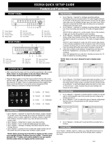
Connections at the rear
Note: Connections optionally for NTSC or PAL operation.
VIDEO OUT
NETWORK
VG
A
RS232
VIDEO IN 1 VIDEO IN 2 VIDEO IN 3 VIDEO IN 4
LOOP 1 LOOP 2 LOOP 3 LOOP 4
AI1 AI2 AI3AI4 ARIG
NO C NC G +
-
1 2 3 4
5
1012 11 679 8
AC IN 100-240V
~
RS-485
No. Designation Functions/connections Example devices
1 VIDEO IN 1-4 Max. 4 video channels Cameras
2 LOOP 1-4 Max. 4 loop-through video channels Cameras
3 NO, C, NC Alarm outputs for external devices Siren, ashing light
4 RS-485 External interface Keyboard, PTZ camera
5 Power supply Mains power connection -
6 NETWORK Network Network cable
7 Reset switch Reset to factory defaults -
8 ARI/GND Reset alarm with external signal Switch
9 AI1 - AI4 Alarm inputs for external devices Sensors
10 VGA PC monitor PC monitor
11 RS232 External interface Remote Control
12 VIDEO OUT Video output Monitor

9
DLR1.1-04/xxxV
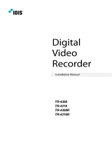
Front panel controls
The following diagram and table set out the controls on the front panel of the DVR:
POWER CAMERA
1 2 3 4
REC ALARM
2 3 6 87
10 9
1 4 5
No. Designation Function
1
POWER
Power-on indicator when DVR is in operation
2 REC
Display when recording
3 ALARM
Display at alarm
4
CAMERA 1-4 Selecting the camera and inputting passwords (primary usage)
PTZ camera functions (secondary assignment)
5
Playback functions / Clip copy (primary usage)
PTZ camera function (secondary usage)
6
Reset alarm
Start/end panic recording
●
●
7 Call up/exit menu
8
Switch to search functions
Use search functions
Menu navigation
Freeze
●
●
●
●
9
PTZ camera on/off (primary usage)
In/out zoom (secondary usage)
10 USB connection

10
DLR1.1-04/xxxV
Key to controls
PTZ camera functions
Element Function
Zoom in
Zoom out
Close-up
Wide-angle
Load preset
Search functions / Menu navigation / Fixed image
Element Display Function
Current camera image
Activating search by recorded images
Start rewind
●
●
Recorded images Frame-by-frame rewind
Menu Upwards
Current camera image
Activating search by recorded images
Start rewind
●
●
Recorded images Quick rewind in 4 speeds
Menu To the left
Current camera image Switching current record > Fixed image
Recorded images
Pause
Switching pause > current record
●
●
Menu OK
Current camera image
Activating search by recorded images
Start forward
●
●
Recorded images Fast forward in 4 speeds
Menu To the right
Current camera image
Activating search by recorded images
Start forward
●
●
Recorded images Frame-by-frame forward
Menu Downwards

11
DLR1.1-04/xxxV
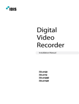
Remote control functions
The following diagram and table set out the functions on the remote control:
Select System ID
DIGITAL VIDEO RECORDER
Remote Cont
ro
lle
r
ID
ZOOM/OFF
CAMER
A
1
2
3
4
PTZ
1
2
3
4
6
5
No. Designation Function
1
Reset alarm
Start/end panic recording
●
●
2
PTZ camera function
(secondary usage)
Playback functions
(primary usage)
3
PTZ camera on/off (primary usage)
ZOOM/OFF
In/out zoom
(secondary usage)
4
Switch to search functions
Use search functions
Menu navigation
Freeze
●
●
●
●
5 Call up/exit menu
6
PTZ camera functions
(secondary usage)
CAMERA 1-4
Selecting the camera and inputting
passwords (primary usage)

12
DLR1.1-04/xxxV
The following illustration shows the structure of the complete menu tree that is accessible using the mouse
control:
Display Camera 1. CAM1
2. CAM2
3. CAM3
2x2
Sequence
Freeze
Zoom...
PTZ... Speed
Auto Pan
Tour
Pattern
Device Menu
Light
Pump
Wiper
Power
Aux.
Move to Origin
Exit PTZ
Note: The number of menu entries in the PTZ menus differs depending on the camera model selected.
Menu structure

13
DLR1.1-04/xxxV
The following illustration shows the structure of the complete menu tree that is accessible using the mouse
control:
Setup Menu... System Information
Date/Time
Storage
User
Shutdown...
Log out user1...
Network Network
Notication
Devices Camera
Alarm-Out
Display
Remote Control
Record Record
Schedule
Pre-Event
Archive
Event Alarm-In
Motion Detection
Video Loss
Text-In
System Event
Event Status
Search Go to... First
Last
Date/Time
Record Table Search...
Event Log Search...
Text-In Search…
Motion Search...
Clip-Copy...
Zoom...
Use De-interlace
Slow Play x1
x1/2
Exit Search
Menu structure (continued)

14
DLR1.1-04/xxxV
Accessing the menus
Accessing the Search menu
Requirement:
The current camera image is shown in full image or quad image.
Step Action Menu path
1
Press one of these keys.
Result: Search for recorded images is activated.
2 Open Search menu... > Search menu
Accessing the Setup menu
Requirement:
The current camera image is shown in full image or quad image.
Step Action Menu path
1
Open Setup Menu...
Result: The password will be requested.
> Setup menu
2
Input the password and conrm it.
Standard password: 4321
OK
Accessing the PTZ menu
Requirement:
A PTZ camera is connected and congured.
Current camera image is shown as a full image.
Step Action Menu path
1
Press the PTZ camera functions key.
Result: The full image is outlined in white.
2 Open PTZ menu... > PTZ menu
●
●
●
●

15
DLR1.1-04/xxxV
Getting started
Checklist for DVR operation
Step Action Menu path
1 Connect peripheral devices as per planned setup.
2 Specify menu language.
Setup menu > System > System Infor-
mation
3 Adjust date and time. Setup menu > System > Date/Time
4 Setting the passwords Setup menu > Password
5
Set up network and desired notication channels
(optional).
Setup menu > Network > ...
6 Register peripherals with DVR. Setup menu > Device > ...
7 Set up event types and associated responses. Setup menu > Event Action > ...
8 Set up recording parameters and schedule. Setup menu > Record > ...
Connecting the remote control and DVR
The Remote Control and Digital Video Recorder can be provided with an ID; when several Digital Video Recor-
ders are used in parallel the ID of each Digital Video Recorder must be unique. The DVR will then only respond
to the remote control with the matching ID. Value range: 1, 2, 3 or 4
If the system ID in the DVR is 0, it will respond to the remote control regardless of the remote’s ID.
If the system ID in the DVR is not 0, you must set the ID of the remote control identically.
Step Action Menu path
1 Set DVR system ID. Setup menu > System > System Information
2
Match remote control to system ID by
pressing ID button on remote control.
3 Select relevant number on remote control.
●
●

16
DLR1.1-04/xxxV
Getting started (continued)
Switching on the DVR
Requirement:
The start-up preparations are complete.
Step Action
1 Plug in DVR mains plug.
2
Switch on monitor.
Result: System starts up automatically and is ready to use.
Switching off the DVR
Requirement:
You have accessed the Setup menu.
Step Action Menu path
1
Shut down the system.
Result: The password will be requested.
Setup menu > System > System Shutdown
2
Input the password and conrm it.
Standard password: 4321
Result: System shuts down automatically.
OK
3 After shutdown, disconnect the mains plug.
●
●

17
DLR1.1-04/xxxV
Administration
Dening Scheduled entries
You can dene schedules for functions and responses to different events.
Schedule for: Dening 2 modes each for: Menu path
Functions Setup menu > ...
Alarm outputs Active or event-triggered
Device > Alarm Out >
Sched
Time-Lapse Record
Record:
Speed of the recording
Recording quality
●
●
Record > Time-Lapse
Record > Sched
Response to
Event at an alarm input
Record:
Camera
Speed of the recording
Recording quality
Alarm Out:
Alarm outputs or beeps
Dwell Time
Notify:
On / Off
●
●
●
●
●
●
Event Action > Alarm In
Action > Sched
Motion detection at a camera
Event Action > Motion
Action > Sched
Text input at a text input device
Event Action > Text-In
Action > Sched
Interruption of recording at a camera
Event Action > Video Loss
Action > Sched
Entering schedule entries
Step Action Menu path
1 Calling up the schedule. Setup menu > … > Sched >
2 Select desired day.
(blank) Every day
S Sunday
M Monday
T Tuesday
M Wednesday
T Thursday
F Friday
S Saturday
H Holidays
3
Assign desired mode:
The whole day or
divided into 30-minute sections
●
●
Blank No records / actions
Blue On or record / action to mode 1
Yellow Event or record / action to mode 2
4 Conrm input. OK

18
DLR1.1-04/xxxV
Administration (continued)
Saving your system setup
You can save your DVR’s setup data, including its network conguration.
Requirement:
USB memory stick
Step Action Menu path
1
Insert USB memory stick in the USB port
2
Calling up export setup. Setup menu > Cong > Load/Save Setup > Save
3
Specify a le name.
4 Export your setup. Save
Loading your system setup
You can load your stored DVR system setup with or without its network conguration.
Requirement:
USB memory stick with stored setup
Step Action Menu path
1
Insert USB memory stick in the USB port.
2 Calling up import setup. Setup menu > Cong > Load/Save Setup > Load
3 Selecting le.
4 Decide whether to include network setup.
5 Import your setup. Load
Deleting recordings
You can only delete all your recordings together. It is not possible to delete recordings from a specic time
period.
Step Action Menu path
1 Delete all recordings. Setup menu > Cong > Clear All Data
●
●

19
DLR1.1-04/xxxV
Administration (continued)
Downloading software updates
You can download software updates for your DVR from a USB memory stick.
Requirement:
USB memory stick with latest software release
Step Action Menu path
1
Insert USB memory stick in the USB port.
2 Start update.
Setup menu > System > System Information >
Change > Upgrade...
3 Install new release. Go
Hide camera display
You can suppress the visible display of the video images and camera data.
Step Action Menu path
1 Setting "concealed" mode for the camera. Setup menu > Device > Camera > Setup
2 Conrm input. OK
Restoring factory defaults
Before restoring the factory defaults, you should export your current system settings in case you need to re-
import them later. (see Saving your system setup and Loading your system setup)
Step Action
1 Shut down the system.
2 Disconnect the mains plug.
3 Push a paper clip into the Reset button (on the rear of the DVR) and hold it there.
4 Plug in the mains plug.
5 Wait until all 3 LEDs are ashing.
6 Withdraw the paper clip.
●

20
DLR1.1-04/xxxV
Determining the memory requirement of a recording
The amount of memory recorded video sequences will take up depends on the following factors:
Picture quality
Number of images per second
Duration
The memory requirement is calculated by this formula:
Memory requirement = picture size x duration of recording x images per second
Calculation example: CIF resolution (PAL):
Picture
quality
Picture
size
Duration of
recording
Approx. memory space
5 images/s 10 images/s 25 images/s
Low 2.4 kB 24 hours 1.04 GB 2.07 GB 5.18 GB
Standard 4.8 kB 24 hours 2.07 GB 4.15 GB 10.37 GB
High 9.6 kB 24 hours 4.15 GB 8.29 GB 20.74 GB
Very High 14.4 kB 24 hours 6.22 GB 12.44 GB 31.10 GB
Calculation example: 2CIF resolution (PAL):
Picture
quality
Picture
size
Duration of
recording
Approx. memory space
5 images/s 10 images/s 25 images/s
Low 4.8 kB 24 hours 2.07 GB 4.15 GB 10.37 GB
Standard 9.6 kB 24 hours 4.15 GB 8.29 GB 20.74 GB
High 19.2 kB 24 hours 8.29 GB 16.59 GB 41.47 GB
Very High 28.8 kB 24 hours 12.44 GB 24.88 GB 62.20 GB
●
●
●
Administration (continued)
/